Smith G.T. Cutting Tool Technology: Industrial Handbook
Подождите немного. Документ загружается.

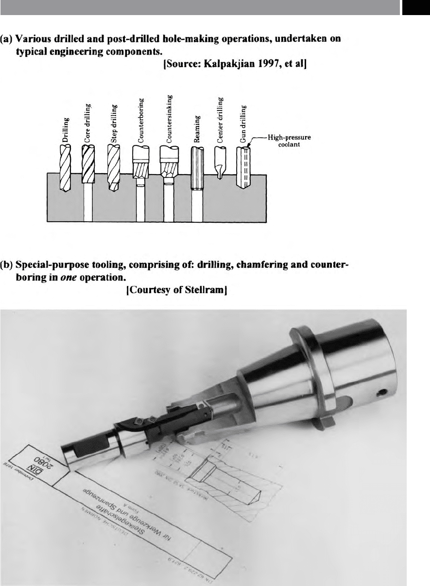
Figure 56. Special-purpose multi-functional tooling can be designed and manufactured to machine many part features
simultaneously
.
Drilling and Associated Technologies 111
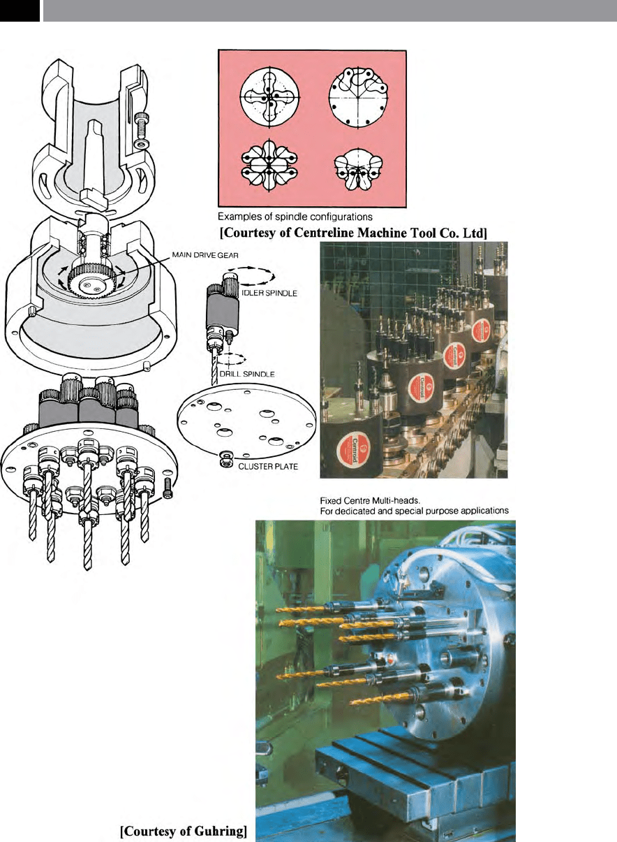
Figure 57. The application of multi-spindle drilling heads to increase productive throughput.
112 Chapter 3

signicant economic savings can be made and their
initial capital outlay will have been worthwhile. How-
ever, such complex and expensive tooling used inap-
propriately can be counter-productive, so consider-
able thought and care should be made into any future
implementation of these tools.
3.1.7 Deep-Hole Drilling/
Gun-Drilling
Deep-Hole Drilling – an Introduction
Deep-hole drilling can be characterised by, high mate-
rial removal rates, having excellent: hole straightness,
dimensional tolerances and machined surface texture.
Deep-hole drilling applications are utilised across di-
verse industrial applications, including: aerospace,
nuclear power, oil and gas, as well as for steel and
chemical processing industries. ese industries place
a high demand on all aspects of drilled hole quality
and reliability, with components being very expensive,
any failures will have severe economic consequences.
e name Deep-hole drilling implies the machin-
ing of holes with a relatively long hole depth to its
diameter. Typically at the lower length-to-diameter
ratios they can be as short as x5 the diameter, con-
v
ersely at the other end of the scale, ‘ratios’ of > x100
the diameter can be successfully generated, with close
t
olerances and a surface texture approaching 0.1 µm
(Ra). ere are a considerable number of deep-drill-
ing production techniques, with each one having an
appropriate usage for a particular hole generation
method. A typical deep-drilling tooling assembly
is essentially ‘self-piloting’ ,
in that the cutting forces
generated are balanced, not with respect to the cut-
ting edges – as is the situation with Twist drills – but
invariably, by pads that are situated at 90° and 180° to
that of the cutting edge. ese pads rub against the
bore’s surface being generated and therefore support
the head, while burnishing
30
the surface. e machine
tools enabling these deep-drilled holes to be generated
can be expensive, along with the appropriate tooling,
but the production costs can be dramatically reduced,
by employing such a machining strategy. One of the
30 Burnishing will improve the surface nish and dimensional ac-
curacy, by plastically deforming the machined surface layers –
cusps – without removing any additional workpiece material.
major problems of utilising Deep-hole drilling, is chip
disposal, as the deeper the hole is drilled, the further
the chip must travel from the cutting edge to the hole’s
exit. is chip evacuation distance, can increase the
probability of chip-jamming, or binding in the ute
as the chip attempts to exit the deep-drilled hole.
Notwithstanding the problems associated with BUE,
which hinders the tool’s ability to break chips. Coolant
control and its operational usage is important in any
the Deep-hole drilling technique, as one of its main
functions is – apart from lubricating/cooling the cut-
ting edge and chip ushing – is to restrict frictional ef-
fects between the: drill, chip and hole wall. Moreover,
if friction builds-up due to poor coolant delivery, this
can result in higher torsional eects, which may cause
the drill to snap.
Gun-Drills
Gun-drills (i.e. see Fig. 58a), are normally utilised to
machine small, straight diameters to high tolerances
and having excellent nishes in a single operation.
Drilled hole sizes can range from as small as φ1
.5 mm
to φ7
5 mm in a single pass, with depths equating to
100 times the tool’s diameter
31
. e ‘drilling system’ is
a highly developed and ecient technique for produc-
ing deep holes in wide variety of workpiece materials,
ranging from: plastics, breglass, to high-strength ma-
terials such as Inconel. is tooling usually consists of
either a cemented carbide, or cemented carbide-tipped
drill head tted to a tube-shaped shank
32
. e former
solid carbide drill head version allows the tooling to
be reground as necessary, while the latter version is
normally employed for larger diameter hole drilling
operations. e drill head has two distinct designs,
e
ither having a ‘kidney-shaped’ , or a cylindrical hole
present, for the delivery of cutting uid, which pro-
vides:
•
Flow of cutting uid – to create the maximum ow
rate and chip-ushing,
31 ‘Special-purpose’ Gun-drills can be produced to generate
drilled holes up to φ150 mm having 200:1 length-to-diameter
ratios, at penetration rates of better than equivalent diameter
Twist drills.
32 Gun-drills would as a rule, have their drill head’s brazed – via
silver soldering – onto a tube-shaped shank, these in turn, are
also brazed onto a ‘driver’ (i.e. of various designs) of the re-
quired length for the successful drilling of long slender holes
in the workpiece.
Drilling and Associated Technologies 113
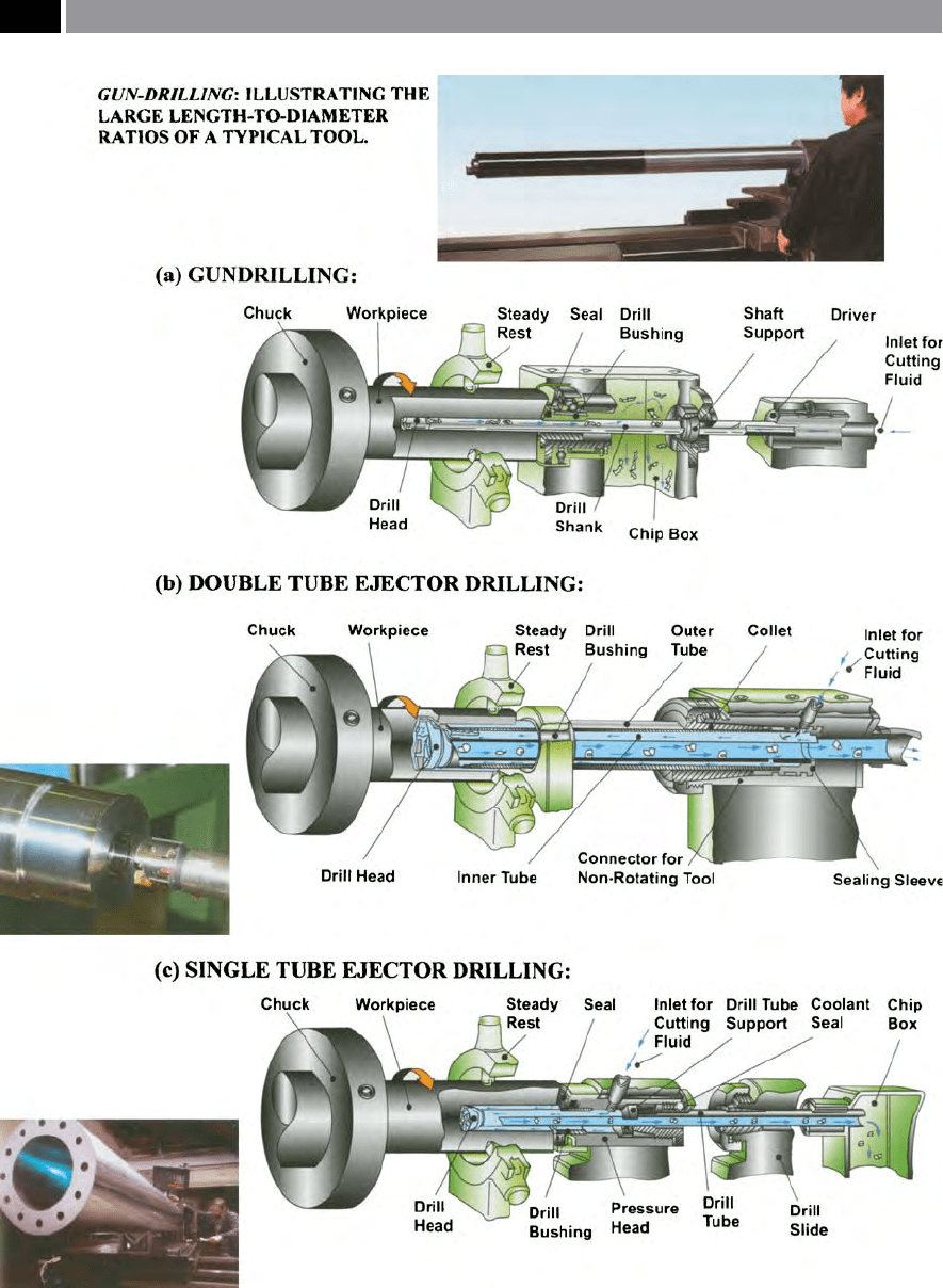
Figure 58. Deep-hole drilling operations, such as: (a) gundrilling, (b) double tube ejector drilling and (c) single tube ejector drill-
ing. [Courtesy of Sandvik Coromant]
.
114 Chapter 3

•
Minimal uid-ow disturbance – giving consis-
tent/regular ow-rate to drill-head,
•
Minimum of uid-turbulence – allowing chips to
be easily evacuated from the cutting region.
Typically, cemented carbide heads, have an external V-
shaped chip-ute which extends along the shank, the
angle of this chip-ute has been experimentally-deter-
mined to be 110°, providing the following advantages:
•
Optimum ute cross-section – allowing the most
rapid cutting uid return and chip transportation,
•
Facilitates an extra support pad – this is necessary
when drilling through crossing holes,
•
Provides optimal torsional strength – important
for workpieces having very long length-to-diameter
ratios,
•
Facilitates tool clamping – enabling the tool to be
held in a three-jaw chuck for convenient regrinding
on a suitable cutter-grinder.
Gun-Drill Failure
One of the main reasons for Gun-drills to fail in op-
eration, is through an excessive misalignment of the
drill bushing and this will be in relation to the drill’s
rotational axis (i.e. see Fig. 58a). is type of align-
ment failure mode is termed a ‘balk-crash’ – caus-
ing the tool to fracture into numerous pieces
33
. If the
drill is rotated rather than the workpiece, the stress is
re-applied to diering portions of the tip and, at the
weakest point, namely the drill’s corner, the tip will
most likely fracture in this region. A potential failure
mode is related to the Gun-drill’s length, which has its
rigidity decreased with increased length
34
. e shank
of a longer Gun-drill will not transmit a large amount
of bending force to the cutting tip – when misaligned
– however, the tip does not fracture, but instead, any
axis misalignment causes the shank to ex with each
revolution, a situation that is ideal for a fatigue fail-
33 ‘Balk-failure’ of Gun-drills is the result of the ‘brittle’ carbide
tip being unable to withstand the bending stresses created by
its unintentional axis misalignment.
34 Gun-drill ‘rigidity rule’: as the drill’s length increases, its ri-
gidity decreases by the ‘cube’ of the distance. For example, if
two identical Gun-drill diameters are employed for drilling
the same workpiece material, then if one drill is twice as long
as the other, then its rigidity will 8 times less rigid than its
counterpart (i.e. namely: 2
3
).
ure mode. Yet another Gun-drill failure situation may
arise if there is excessive clearance between the drill
bush and the drill’s tip. Under these circumstances, the
Gun-drill’s edge cuts a signicant volume of workpiece
material and, as this edge is not designed to cut – hav-
ing a zero clearance angle (i.e. created by the circular
margin at this edge) – the excessive cutting forces
cause the edge to prematurely fracture.
If insucient coolant ow occurs, this is also a typ-
ical factor in subsequent Gun-drill failure. is lack of
coolant causes the chips to pack in the V-ute, forming
a plug, which then creates excessive torque in the Gun-
drill and, this plug allows the tip to separate away from
the shank. Occasionally, end-users blame the Gun-drill
tooling manufacturer for poor brazing, if the tool’s tip
separates from the shank. However, when analysis of
the brazed fractured surfaces occurs, invariably, small
carbide particles are adhered to the shank, this being
evidence of the fact that the braze was stronger than
the tip, clearly demonstrating that the brazing was not
at fault.
In many circumstances, the Gun-drill tool manu-
facturer is blamed by the customer for its failure dur-
ing machining, but when investigated, it is usually
premature failure being the result of a poor tooling
installation and operation. One of the major causes of
Gun-drill failure, is via the coolant distribution sys-
tem, where inconsistent delivery of the uid can either
‘starve’ the Gun-drill’s cutting edge, or ‘over-ood’ the
system. One of the major factors contributing to this
over-/under-supply of coolant delivery, is due to the
fact that in the main, coolant pressure is being moni-
tored, rather than the measurement of coolant ow-
r
ate. If holes are Gun-drilled < φ4 m
m, then high-pres-
sure coolant ow-rate to the point is essential, but in
many cases of coolant systems tted to ‘standard’ ma-
chines, they are of relatively low-pressure delivery. Re-
cently, one machine tool manufacturer, has designed
and developed a coolant intensier pump coupled to
a special high-pressure union, which gives variable
pump pressures of over 200 bar, with special-purpose
couplings to overcome the problems of poor coolant
ow-rates to the cutting vicinity.
3.1.8 Double-Tube Ejector/Single-
Tube System Drills
Double-tube Ejector drills (i.e. oen just termed ‘Ejec-
tor Drills’), are designed around a twin tube system
Drilling and Associated Technologies 115

(i.e. see Fig. 58b – for the schematic and inset a photo
of the drill head). Here, the self-contained system (i.e.
not requiring specic sealing arrangements), of the
cutting uid, is externally pumped along the space be-
tween the inner and outer tubes. e major portion of
the cutting uid is fed forward to the drill head, while
the remainder is forced through a groove in the rear
section of the inner tube. A ‘negative pressure’ occurs
in the front portion of the inner tube, which causes the
cutting uid at the drill head to be sucked out through
the inner tube along with the chips. As is the case for
Gun-drilling coolant supply, it must be of sucient
pressure and volume, to overcome any likelihood of
‘starvation’.
e ‘ejector head’ of the drill comprises of: a con-
nector, outer and inner tubes, a collet and sealing
sleeve, together with a drill head. Disposable heads
with cemented carbide tips are utilised for diameters
ranging from 18.5 to 65 mm, normally supplied with
two types of cutting edge geometries, with the carbide
cutting tips precisely located on either side of the drill
head. e asymmetric design
35
of these ‘Ejector Drills’
has support pads provided, to absorb the radial cut-
ting forces and guide while supporting the tool as it
penetrates into the workpiece. At the commencement
of the deep-drilling operation, the drill bushing’s main
function
36
(i.e. shown in Fig. 58b), is to guide and sup-
port the drill at initial workpiece entry and until drill
penetration allows the support pads to bear on the
partially-drilled hole surface and thereupon remain-
ing in contact throughout the drilling operation.
Whilst deep-hole drilling, the drill and workpiece
centrelines must not deviate by > 0.02 mm, so any sub-
sequent drill bush wear needs to be carefully moni-
tored and controlled. It is usual practice to have a ro-
35 Asymmetric Drill Head design, refers to the fact that the
cutting inserts are not only radially, but are angularly oset.
erefore, they normally require two support pads to counter-
act and sustain the radial cutting forces generated while dril-
ling deep holes. By locating the cutting inserts on both sides
of the drill head, the greater percentage of radial forces are
negated at these pads.
36 Drill bushing tolerances between the drill and bush for both
the ‘Ejector’ and Single-tube Systems, require a t of ISO G6/
h6, equating to a minimum play of 0.006 mm. is drill bush
is usually manufactured from a hardened material (i.e. 60 to
62 HR
C
) such as cemented carbide, as it has a longer service
life, with bush wear normally limited to 0.03 mm.
tating workpiece and a stationary tool, with any centre
divergence resulting in bell-mouthing at the hole’s en-
trance and a wavy hole surface. Once the support pads
in the drill head have moved x5 their length down the
drilled hole, then any further waviness is negligible, as
they begin to press down on the hole’s curvature. Many
deep-drilled hole prole and tolerance abnormalities
result from centre divergence, which needs special at-
tention to minimise such eects.
Single-tube [Ejector] System drills (i.e. commonly
referred to and abbreviated as simply ‘SST’) are sche-
matically depicted in Fig. 58c. With this SST tooling
assembly, the cutting uid is pumped under pressure
between the drill and the hole wall (i.e. normally this
width of space is approximately 1 mm) and it exits
with chips through the inside of the drill tube (Fig.
58c). e quantity of cutting uid passing through the
drill is twice as great and with higher pressure, than
for an equivalent ‘Ejector’ tooling assembly. Hence, the
SST set-up provides improved chip-breaking and mi-
nimises any potential chip-jamming, even when vary-
ing chip lengths occur.
e drill head arrangement of cutting inserts will
vary from two, three, or more, depending on the drill’s
diameter, usually made of cemented carbide, oen as
brazed over-lapping tips, although disposable index-
able pocketed inserts with chip-breakers are oen
utilised for larger diameter holes. SST tools can be used
to drill small diameter holes, ranging from φ12.5 mm
upward, with 100:1 depth-to-diameter ratios. e SST
tooling system copes with dicult-to-machine work-
piece materials, such as Monel, Inconel and Hastel-
loy and other ‘exotic materials’. In actual production
machining trials, it has been found that SST tools can
produce deep-drilled holes up to 15 times faster than
is achievable by conventional Gun-drilling. is high
production output level gives an 80% improvement
in machining rates for this SST Deep-drilled hole
production output and, it has been shown in several
instances, to give a ‘Return on Investment’ (ROI)
37
in
about 6 months.
37 Return on Investment (ROI), for Deep-hole drilling operati-
ons (i.e. in % terms), is given (i.e. in simplistic terms) by the
following formula:
% ROI =
Cost of a -to- productivity gain
Total conversion cost
116 Chapter 3

3.1.9 Deep-Hole Drilling –
Cutting Forces and Power
In Deep-hole drilling operations, the underlying the-
ory for the calculation of cutting forces and for torque
are similar to that utilised for ‘conventional’ drilling
operations. e major dierence between the hole
production calculations for Deep-hole drilling to that
of ‘conventional hole-making’ techniques, lies in the
fact that support pads create a sizeable level of fric-
tional forces, that cannot be ignored. ese increased
frictional eect contributions – by the pads – to the
overall Deep-hole drilling cutting forces and torque
values are somewhat dicult to precisely establish,
however, an approximate formulae can be used to esti-
mate them, as follows:
Feed force (N):
F
p
+ F
pµ
= 0.65 × k
c
× a
p
× f × sinκ
r
Where:
F
p
= Feed force, or drilling pressure (N),
F
pµ
= Force and Frictional eects (N),
k
c
= Specic cutting force (N mm
–1
),
a
p
= Depth of cut (mm),
f = Feed per revolution (mm rev
–1
),
sinκ
r
= Entering angle (°).
Torque, or Moment (Nm):
M
c
+ M
µ
=
k
c
� a
p
� f � D
(. − a
p
�D)
Where:
M
c
= Torque cutting (Nm),
M
µ
= Torque and Frictional eects (Nm),
k
c
= Specic cutting force (N mm
–1
),
a
p
= Depth of cut (mm),
f = Feed per revolution (mm rev
–1
),
D = Hole diameter (mm).
Relatively high speeds are utilised for Deep-hole Drill-
ing operations, in order to achieve satisfactory chip-
breaking, this necessitates having a machine tool with
a reasonable power availability.
e underpinning theory for calculating the power
requirements, corresponds with that of ‘conventional’
drilling operations. However, the friction forces that are
present, due to the employment of support pads, gives
rise to a torque contribution (M
µ
), which in turn pro-
duces an associated contribution ‘P
µ
’ to the total Deep-
hole drilling power. erefore, in order to estimate the
machine tool’s power requirement (i.e. ‘P’ in kW ), an
allowance must be made for any power losses in the
machine tool. Hence, the gross power required can be
established by dividing the Deep-hole drilling power
(i.e. P
c
+ P
µ
), by the machine tool’s eciency ‘η’. is
eciency indicates what percentage of the power sup-
plied by the machine tool, that can be utilised, while
Deep-hole drilling.
Power (kW):
(P
c
+ P
µ
) =
k
c
� a
p
� f � v
c
,
(. − a
p
�D)
Where:
P
c
+ P
µ
= Power contributions of: cutting and friction
respectively (kW),
v
c
= Cutting speed (m min
–1
).
∴P = P
c
+ P
µ
/η
Where:
η = Machine tool eciency.
3.2 Boring Tool Technology –
Introduction
e technology of boring has shown some important
advances in recent years, from advanced chip-break-
ing control tooling (i.e. see Fig. 59, this photograph
illustrates just some of the boring cutting insert ge-
ometries that can be utilised), through to the ‘active
suppression of chatter’
38
– more will be mentioned on
the topic and reasons why chatter occurs and its sup-
pression later in the text. Probably the most popular
type of boring tooling is of the cantilever type (Fig.
59), although the popularity of either ‘twin-bore-’ , or
38 ‘Chatter’ , is one of the two basic types of vibration (i.e.
namely, ‘forced’ and ‘self-excited’) that may be present dur-
ing machining. In the main, chatter is a form of self-excita-
tion vibration.‘[It is]… due to the interaction of the dynamics
of the chip-removal process and the structural dynamics of the
machine tool. e excited vibrations are usually very high in
amplitude and cause damage to the machine tool, as well as
lead to premature tool failure’. [Aer: Kalpakjian, 1984].
Drilling and Associated Technologies 117

‘tri-bore-heads’ , with ‘micro-bore adjustment’ of the ei-
ther the individual inserts, or having a simultaneous
adjustment of all of the actual cutting inserts, is be-
coming quite common of late.
Boring operations invariably utilise cantilevered
(i.e. overhung) tooling, these in turn are somewhat
less rigid than tooling used for turning operations.
Boring, in a similar manner to Deep-hole drilling and
Gun-drilling operations, has its rigidity decreased by
the ‘cube’ of the distance (i.e. its overhang), as the fol-
lowing equation predicts:
f
o
=
π
�
� EI
L
(M
t
+.M
b
)
Where:
f
o
= normal force acting on the ‘free end’ of the can-
tilever (i.e boring tool overhang),
*EI = exural stiness (i.e. I = cross-sectional moment
of Inertia) (Nm
2
),
M
t
= boring bar mass (kg),
L = length of cantilever (mm),
M
b
= Modulus of elasticity of the boring bar
(N mm
–2
).
* E, relates to the boring bar’s ‘Young’s modulus’.
Boring a hole will achieve several distinct production
criteria:
•
Enlargement of holes – a boring operation can en-
large either a single, or multiple series of diameters,
to be either concentric to its outside diameter (i.e.
O.D.), or machined eccentric
39
(i.e. oset) to the
O.D.,
•
Correction of hole abnormalities
40
– the boring
process does not follow the previously produced
39 ‘Eccentric machining’ of the bore of a component with respect
to its O.D., was in the past accurately achieved by ‘Button-bo-
ring’ – using ‘Toolmaker’s buttons’ (i.e. accurately ground and
hardened buttons of ‘known diameter’) that were precisely o-
set using gauge blocks (i.e ‘Slip-gauges’). is technique might
still be employed in some Toolrooms, but normally today, on
CNC-controlled slideways, a simple ‘CNC oset’ will achieve
the desired amount of bored eccentricity.
40
Correction of hole abnormalities, as Fig. 60 schematically il-
lustrates, how boring can correct for ‘helical wandering’ of the
drill as it had previously progressed through the workpiece.
e drill’s helical progression would cause undesirable hole
eccentricity, resulting from minute variations in its geometry,
hole’s contour, but generates its own path and will
therefore eliminate drill-induced hole errors by the
subsequent machining operation (i.e. see the sche-
matic representation shown in Fig. 60),
•
Improvement of surface texture – the boring tool
can impart a high quality machined surface texture
to the enlarged bored hole.
NB In this latter case, boring operations to previ-
ously drilled, or to any cored holes in castings, can be
adjusted to give exactly the desired machined surface
texture to the nal hole’s dimensions, by careful ad-
justment of the tool’s feedrate and the selection of an
appropriate boring tool cutting insert geometry.
3.2.1 Single-Point Boring Tooling
‘Traditional’ boring bars were manufactured as solid
one-piece tools, where the cutting edge was ground
to the desired geometry by the skilled setter/operator,
which meant that their useful life was to some extent
restricted. Later boring bar versions, utilised indexable
cutting inserts, or replaceable heads (Fig. 61). Boring
bars having replaceable heads are versatile, with the
same bar allowing dierent cutting head designs and
cutting inserts (Fig. 61a). Here, the insert is rigidly
clamped to the tool post, with replaceable ‘modular
tooling’ heads with the necessary mechanical coupling
to be utilised (i.e. Fig 61b), oering ‘qualied tooling’
41
dimensions.
necessitating correction by a boring operation. is ‘correc-
tion’ is necessary, because the drill’s centreline follows the
path indicated, ‘visiting’ the four quadrant points as it spirally
progresses through the part. Hence, hole eccentricity along
with harmonic departures from roundness can be excessive,
if the drill’s lip lengths and drill point angles are o-centre.
e cross-hatched circular regions represent the excess stock
material to be removed by the boring bar, where it corrects
these hole form errors, while machined surface texture is also
considerably improved.
41 ‘Qualied Tooling’ , refers to setting the tool’s osets, with all
the known dimensional data for that tool, allowing for ease of
tool presetting and ecient tool-changing – more will be said
on this subject later in the text.
118 Chapter 3
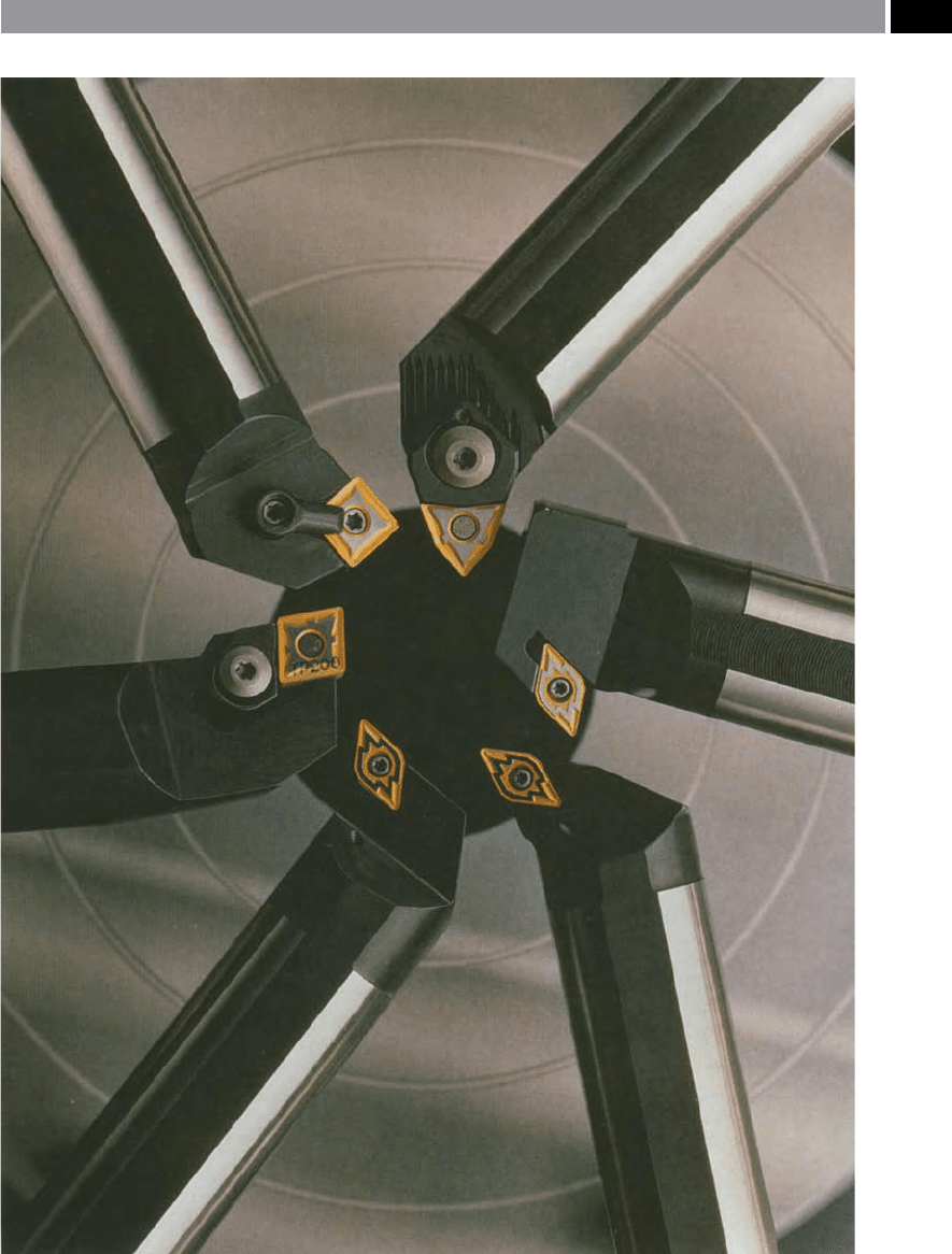
Figure 59. A selection of some tooling that can be employed for boring-out internal rotational features. [Courtesy
of Seco Tools]
.
Drilling and Associated Technologies 119
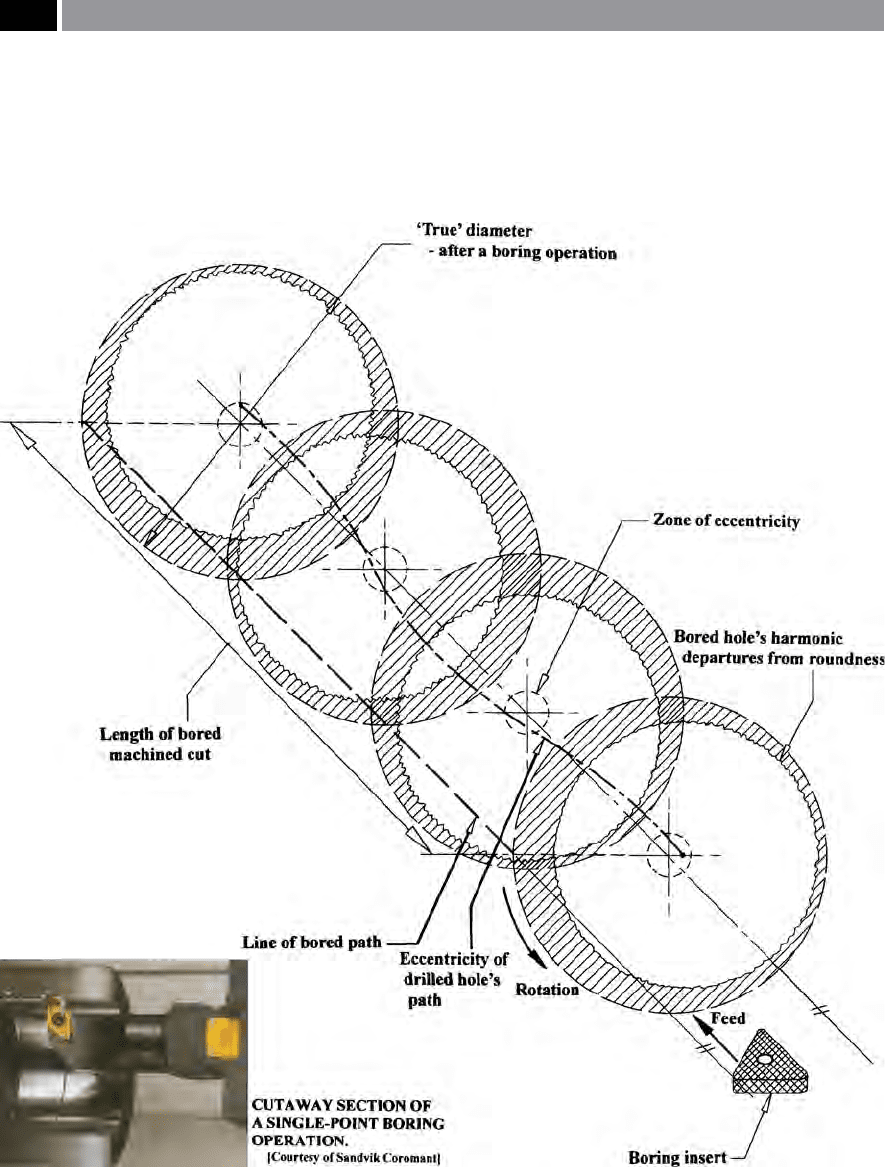
Figure 60. The harmonic and geometric corrections by a boring operation, to correct the previous helical drift, resulting from
the drill’s path through the workpiece
.
In the case of the boring bar’s mechanical interface
(i.e. coupling) example shown in Fig. 61a- top, the ser-
rated V-grooves across the interface along with the
four clamping screws provide an accurate and secure
tment for the replaceable head, with internal tension
adjustment via the interior mechanism illustrated.
120 Chapter 3