Smith G.T. Cutting Tool Technology: Industrial Handbook
Подождите немного. Документ загружается.


this creates potential tool deection which could
become a major problem.
Boring Bar Deflection
When any boring operations take place, even with a
very rigid tool mounting and a small boring bar over-
hang, some vibration and tool tip deection will in-
evitably occur, this is exacerbated by machining hard-
parts. e former problem of vibration has previously
been mentioned and methods of minimising it are
possible. However, tool deections are more dicult,
if not impossible to completely eliminate, with these
longer cantilevered tools. Of note regarding overhang-
ing tool deections, are that a tool tip deects in two
directions (i.e. see Fig. 66a), these are:
•
Radial deection (∆
T
) – aects the machined (i.e.
bored) diameter,
•
Tangential deection (∆
R
) – causes the tip to move
downward for the centreline.
In each of these tool tip deections, both the size and
direction of the cutting forces are inuenced by the
chip thickness and insert geometry selected (i.e. illus-
trated in Fig. 66b). e radial deection will be equal
to the dierence between the diameter which was orig-
inally set and the actual bored diameter, this can be
easily found by the simple expedient of measuring it,
then adjustment can be made for this apparent deec-
tion. e tangential deection of the boring bar’s tip
can be established by either ‘direct’ , or ‘indirect’ met-
rological techniques at the tool’s tip. In Fig. 66a, the
graph depicts deections ‘∆’ (i.e. both the tangential
‘∆
T
’ and radial deection ‘∆
R
’), as a function of the
cutting depth ‘a
P
’. Due to the fact that the tangential
deection (∆
T
) linearly increases with increasing D
OC
(a
P
), it is usually recommended that machining passes
are divided into a number of cuts when close toler-
ances are needed (i.e. in the region of IT7
48
) – see Table
5
49
for an abridged version of the IT tolerances, with
*Rmax values in µm.
e magnitude of radial deection as a function
of the cutting depth, is also inuenced by the ratio
between the insert’s nose radius and the D
OC
(a
P
), to-
gether with the boring insert’s entering angle. In some
cases, a boring bar is situated slightly above the work-
piece centreline, so that when it enters the cut at full
depth it will have tangentially-deected to the actual
48 ‘IT’ (i.e. in units of µm) – represents the average value of the
basic tolerance for the ‘diameter range’ in question. Hence, it
will vary according to the choice of diameter range selected.
49 ese values are related to surface texture expression of:
*Rmax (µm), which is: e maximum individual peak-to-val-
ley height. e Rmax values (i.e. in Table 5) can be calculated
from the IT value, using the following equation, rather than
the conventional equation: Rmax = (fn
2
/r
ε
) 125
this equation tends to give excessively high surface texture va-
lues, thus more practical values related to IT are to be found
from:
�
Rmax =
�
IT
n � IT
(µm)
Where: n = e number of IT’s.
Table 5: IT values related to the basic tolerance for various diameter ranges
Dc (mm): Over /up to
-/3
Over/up to
3/10
Over/up to
10/50
Over/up to
50/180
Over/up to
180/400
Over/up to
400/800
IT5 0.6 0.8 1.3 2.2 3.2 4.5
IT6 0.9 1.2 1.9 3.1 4.6 6.4
IT7 1.4 1.9 3.1 5.0 7.4 10.1
IT8 2.0 2.9 4.7 7.8 11.5 15.8
IT9 3.6 7.5 9.4 12.4 18.3 25.2
IT10 5.7 7.6 12.1 20.0 29.8 40.5
IT11 8.6 11.8 19.1 31.4 46.2 63.8
[Source: Sandvik Coromant (1995)]
.
Drilling and Associated Technologies 131
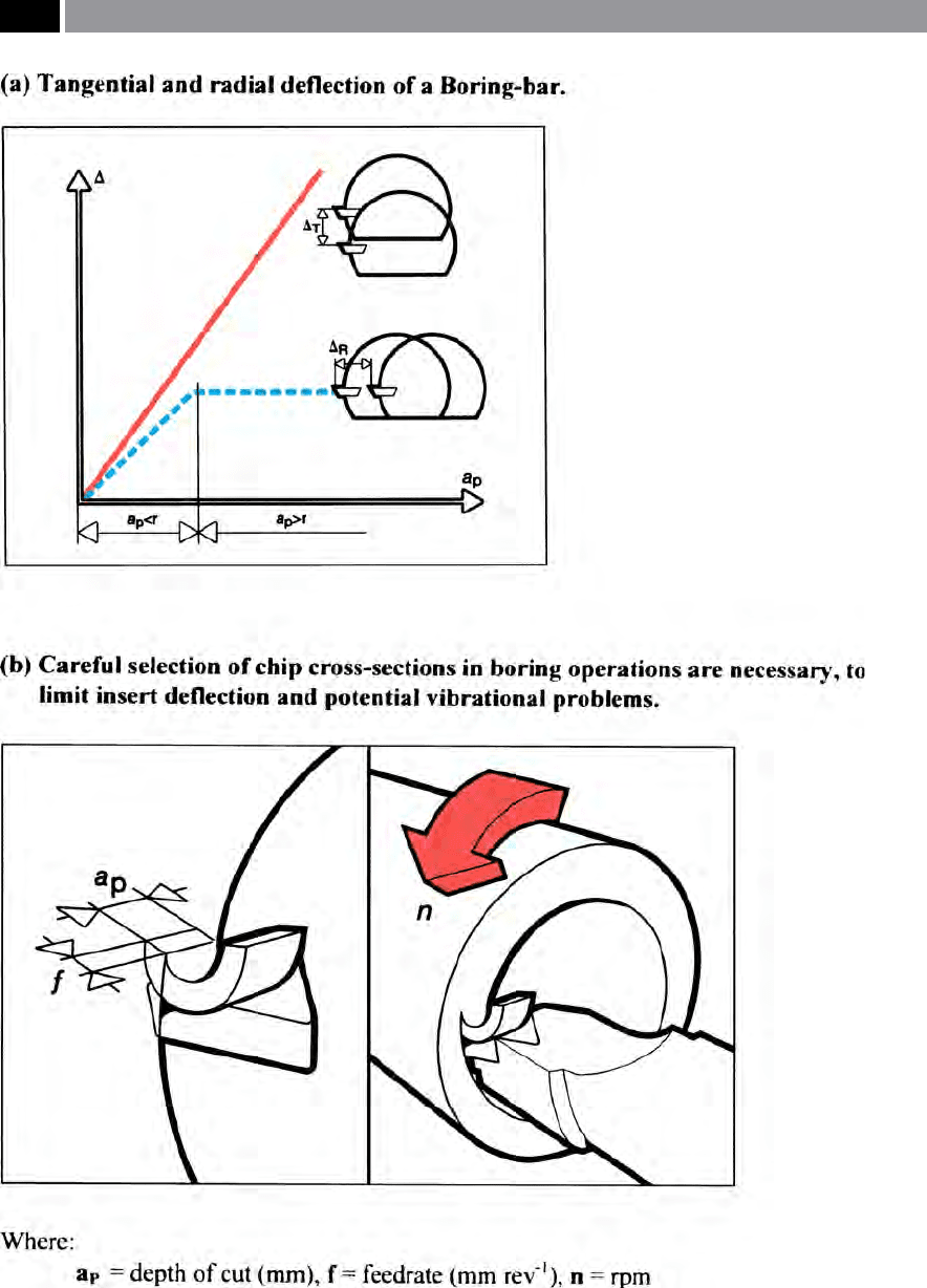
Figure 66. Hard-part boring, can create excessive boring bar deections and potential vibrational problems – if not carefully
controlled. [Courtesy of Sandvik Coromant]
.
132 Chapter 3
workpiece’s centreline. Boring bar overhang is not a
problem when ‘Line-boring’
50
as the tool is supported
at both ends, or in the case of the novel ‘Telescopic line-
boring tooling’
51
.
e chip area (i.e. illustrated in Fig. 66b – right), has
an eect on the load on the insert’s cutting edge, par-
ticularly when hard-part boring, although with small
chip areas, this may not create a vibration problem,
unless high friction is present between the insert and
workpiece. However, the cutting forces substantially in-
crease if a large chip area is utilised, necessitating some
means ‘damping stability’ to the boring tool.
3.3 Reaming Technology –
Introduction
e reamer is the most commonly utilised tool for the
production of accurate and precise holes, having high
surface quality being true to form and tolerance. Ma-
chine reamers can have either a single-blade design
(Figs. 67 and 68), or are produced with a multiple series
of cutting edges – of constant diameter (Fig. 69) or, ta-
pered (Fig.73b) across a diverse range of diameters and
lengths. e surface texture quality obtainable by ream-
50 ‘Line-boring’ , as its name implies is utilised for boring part’s
with concentric and oen varying diameters throughout the
overall component’s length. Normally, a ‘Line-boring tool’ is
supported by a steady with suitable bushing and a mating ex-
tension bar, some distance from the cutting edge and its re-
spective rotating toolholder. is additional support enabling
long bored features to be precisely machined to the part’s cen-
treline in-situ.
51 ‘Telescopic line-boring tool’ , One major machine tool builder
in association with a tooling manufacturer, produced a rather
novel and clever ‘Telescopic line boring tool‘, for the machining
of quite long cranksha bearing housings on both automo-
tive engine blocks and bored cam-seatings for cylinder heads.
is uniquely-designed ‘Telescopic line-boring tool’ , machined
the rst bore, then continued to extend (i.e. telescopically
feed-forward), whilst supporting its progress by mating with
each automotive-machined bore, as it progressed through the
large automotive component, thereby supporting the machin-
ing operation throughout its boring cycle, then retracting on
completion, allowing the tool to be held in the machine tool’s
magazine, allowing/facilitating an ecient and speedy multi-
ple in-line boring operation to be executed.
ing ranges from approximately ‘Ra’
52
0.2 to 6.5 µm, ac-
cording to recommendations of DIN 4766. Normally,
reamed nishes of about Ra 0.5 µm can be regarded as
satisfactory. In general, reaming achieves tolerances of
IT7, but if the reamer has been carefully ground, it can
achieve tolerances of IT6, or even to IT5.
52 Arithmetic roughness ‘Ra’ parameter – it is the arithmetic
mean of the absolute ordinate values Z(x) within the sampling
length. It is the most frequently quoted international surface
texture (i.e. amplitude) parameter, expressed in the following
manner:
Ra =
lr
l r
�
� Z(x) � dx
NB In the past and specically in the USA, its equivalent
term was known as the ‘Arithmetic Average’ , denoted by sym-
bols: ‘AA’.
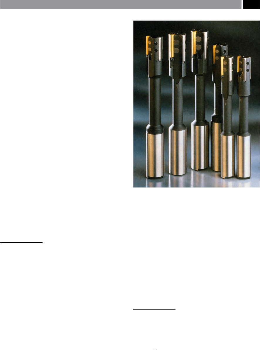
Figure 67. A sample of indexable insert reamer technology –
for solid and oating reamer applications. [Courtesy of Seco
Tools]
.
Drilling and Associated Technologies 133
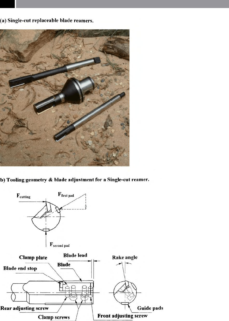
Figure 68. Single-blade reamers oer superior hole geometry over conventional reamers.
[Courtesy of Shefcut Tool & Eng’g Ltd.]
.
134 Chapter 3

Prior to beginning the reaming process
53
, holes
have to be either pre-drilled, or holes cored-drilled
54
.
Due to the nature of the role of the burnishing pads on
the hole’s machined and highly-compressed surface in
Gun-drilling operations, it is not particularly suitable
for reaming.
Machine reamers can be divided into several cat-
egories, these are: multi-point reamers with either
a straight, or Morse taper
55
shank, these reamers are
usually either manufactured from: HSS, Tungsten
carbide (Solid), or with carbide tips. Typically, the
Tungsten carbide (solid) reamers can be run at 10%
higher feedrates, to their HSS equivalents and can
ream workpiece materials up to a tensile strength of
1
200 N mm
–2
.
Machine reamers are available with: straight utes,
le-hand (LH) spirals, or 45° LH ‘quick’ spirals this lat-
ter reamer version is oen termed a ‘Roughing reamer’
and is oen used for ‘long-chipping’ workpiece mate-
rials. Reamers with straight utes are usually utilised
to ream blind holes, but with the absence of chip space
at the bottom, this means that swarf must be evacuated
by the utes. For virtually all other machining tasks,
such as holes with keyways, or intersecting holes, etc.,
53 ‘Hand-reamers’ , are available for the reaming both cylindrical
and tapered holes.
NB A basic rule to be observed when hand-reaming, is to
only turn the tool in the cutting direction and, never reverse
it (e.g. is is the standard practice in cutting a thread with
hand taps), as the reamer’s cutting edges will immediately be-
come blunt.
54 ‘Core-drilling’ ,
this is normally undertaken with a multi-
uted drill, as the hole already exists in the cast component
and in the main, the drill cuts on its periphery, so needs more
cutting edges in contact with the cored hole. Coring is result
of employing a core, prior to casting and it stays in the cavity
as the molten metal is gently poured to cast the part (i.e. cores
are normally made from an appropriate sand and binder, or
another suitable material, that can be removed at the ‘fettling
stage’ – leaving the hole), hence, its name: cored hole.
55 ‘Morse taper’ ,
was developed in the USA in the mid-to-late
1800’s by Steven Morse (i.e famed for his design and develop-
ment of the original geometry for the Twist drill). e Morse
taper is a ‘self-holding taper’ , which can be suitable sleeved ei-
ther upward, or downward in ‘ioned diameter’ to t the inter-
nal taper for the machine tool’s spindle/tailstock, requiring a
‘dri’ to separate the matching tapers upon completion of the
work. e Morse taper’s included angle varies marginally, de-
pending upon its Number (i.e ranging from 0 to 6). Typically,
a ‘No. 1’ is: 2° 58´ 54´ ´, with a ‘No. 6’ being: 2° 59´ 12´ ´.
LH spiral reamers are employed. e chip direction is
always in the feed direction and, for this reason, the
spiral ute geometry is virtually exclusively used for
through hole reaming operations.
3.3.1 Reaming – Correction
of Hole’s Roundness Profiles
Machine Reaming
In the ‘classical’ reaming operation, it is centre-drilled,
then the hole is through-drilled possibly producing
a variety of hole form harmonic out-of-roundness
errors present (i.e. see Fig. 70 ‘polar plots’ – bottom
le), including ‘
bell-mouthing’
56
at the entry and exit
of through drilled holes. Not only is there a possibil-
i
ty of ‘bell-mouthing’ , but a serious likelihood of the
drill following a helical path through the part, this is
termed: ‘helical-wandering’ (
i.e. see ‘Footnote No. 3’ ,
for an explanation of this drilling condition). By a fol-
lowing boring operation, this will correct for any prole
errors, while improving both the part’s overall out-of-
roundness
57
as exhibited by the ‘polar plots’ (ie. as il-
lustrated in Fig. 70 middle-le), but the hole’s ‘cylin-
d
ricity’
58
. Finally, the machine reamer is used to full
several functions: improve both the harmonic out-of-
56 ‘Bell-mouthing’ , is the result of the unsupported drill (i.e.
the margins as yet, not in contact with the drilled hole’s side
walls), producing the so-called ‘bell-mouth prole’ , upon hole
entry. At exit, if the drill is allowed to feed too far past the un-
derside of the hole, the drill has a ‘whipping-tendency’ , which
could introduce a smaller ‘bell-mouthing eect’ beneath the
part’s lower face.
57 ‘Out-of-roundness’ ,
was a term previously utilised, but today,
the term used has been changed to: ‘Departures from round-
ness’ , moreover, the term ‘polar plot’ has also been super-
seded by the term ‘displayed prole’ , however, in the current
context the former terms will be used.
58 ‘Cylindricity’ ,
is the term dened as: ‘Two, or more roundness
planes used to produce a cylinder where the radial dierences
are at a minimum’.
NB A more easily-understood appreciation of what ‘cylindric-
ity’ is, can hopefully be gained by the following ‘working ex-
planation’: If a perfectly at plate is inclined at a shallow angle
and, a parallel cylindrical component is rolled down this plate,
then if it is ‘truly round’ as it rolls there should be no discern-
ible radial/longitudinal motion apparent. In other words, the
component is a truly round cylinder, which can be equated to
a hole, or indeed, to a turned, or ground diameter.
Drilling and Associated Technologies 135
roundness (Fig. 70 top-le) and surface texture, while
‘sizing’ the hole’s diameter.
To further emphasise the point that drilling does
not produce a consistent harmonic out-of-roundness,
nor even a straight hole, Fig 71a, illustrates how the
‘polar plots’ are fundamentally modied at dierent
hole depths, here the ‘plots’ are shown near the top,
in the middle and close to the bottom of the drilled
hole. Correction of these roundness and diametrical
errors by machine reaming is not always the case, here
(i.e. shown in Fig. 71b), if the reamer is either not set
up correctly, or is slightly axially bent, in this case a
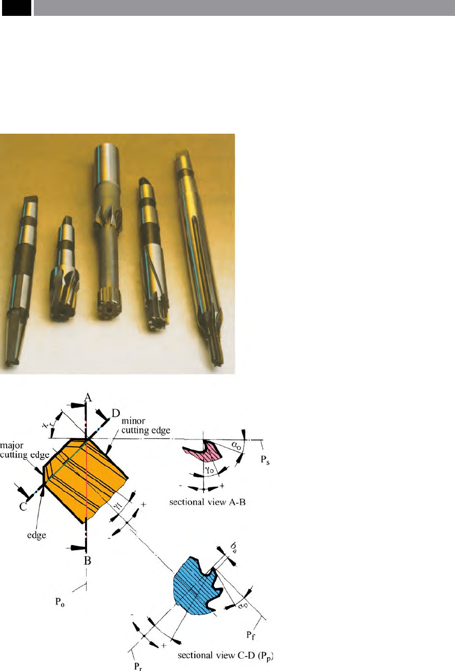
Figure 69. Types of solid reamer and their
associated geometry. [Courtesy of Guhring Ltd.]
.
136 Chapter 3
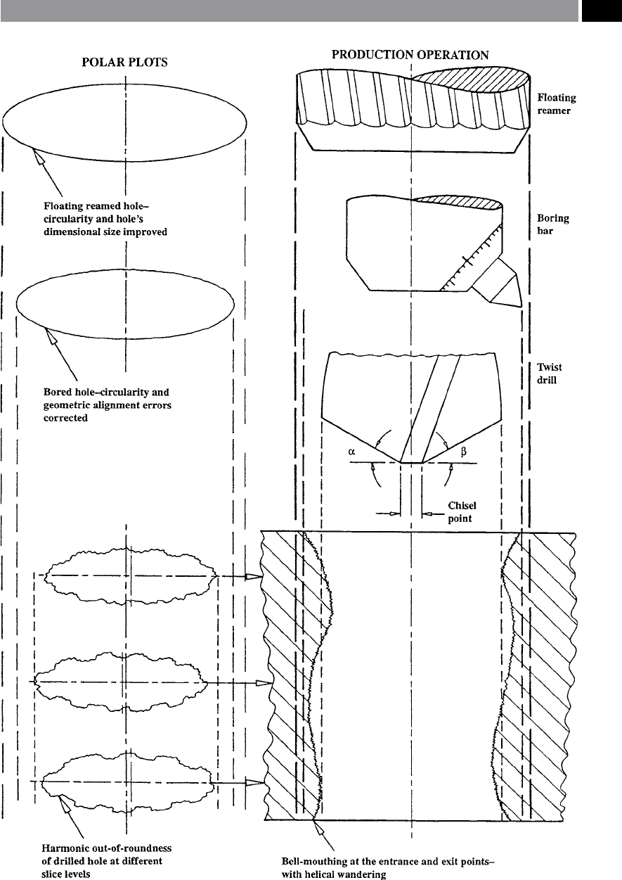
Figure 70. The exaggerated hole errors caused by an incorrect drill point geometry and the manufacturing techniques
for its subsequent correction
.
Drilling and Associated Technologies 137
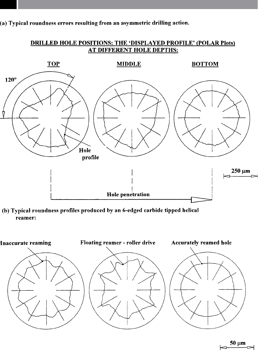
Figure 71. Reaming can correct an assymetrically drilled hole – when correctly adjusted.
138 Chapter 3
large harmonic variation in the ‘plots’ is depicted, as is
the case when a ‘Floating reamer’ with roller drive has
been used inappropriately.
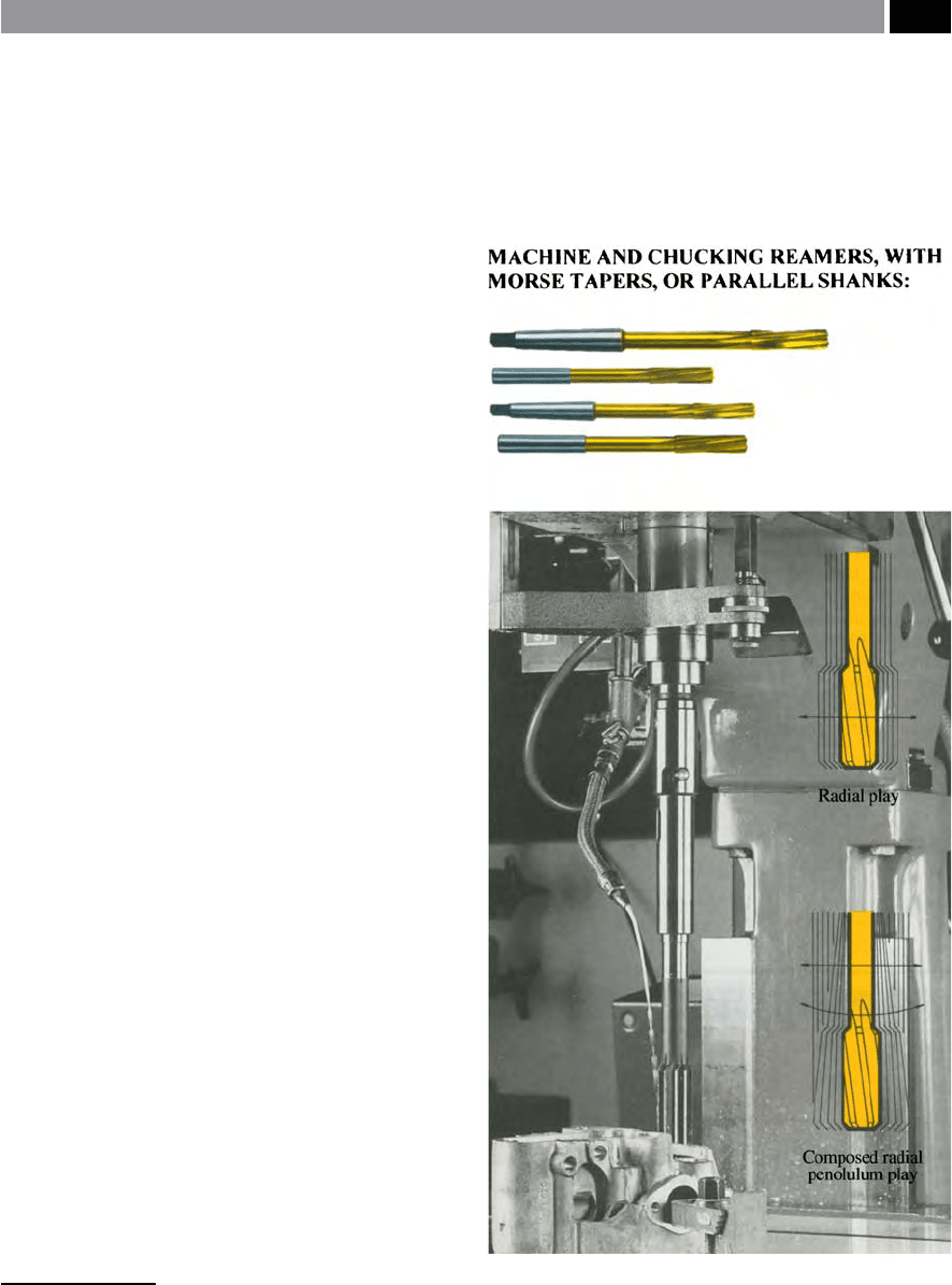
Floating Reaming
Solid machine reamers can be ‘oated-down’
59
a pre-
drilled hole, to produce a much straighter reamed
hole, than would otherwise be the case. When ‘oat-
ing’ reamers within their specially-located toolhold-
ers, two techniques are used to ‘oat reamers’ (i.e see
Fig. 72), these are:
1
. Radial play – where the machine reamer has lim-
ited movement laterally with respect to the princi-
pal axis,
2
. Composed radial and pendulum play – this has
both radial play, together with a degree of limited
angular movement (i.e. this motion is similar to
that of a Grandfather clock’s timing mechanism, via
its pendulum motion).
NB is latter ‘oating’ technique has the potential for
a combination of both radial and pendulum motions
to the machine reamer. ese unrestrained kinematic
motions gives it free motion without lateral and angu-
lar constraint, to simply follow the ‘line of least resis-
tance’ along the spindle axis, as the reamer progres-
sively feeds down through the predrilled workpiece.
3.3.2 Radially-Adjustable
Machine Reamers
Special-purpose machine drill/reamers (Fig. 74a)
are oen utilised in high-volume production envi-
ronments such as in the automotive sector, for util-
ity engines which can account for >55,000 complex-
reaming operations per week. Conversely, for defence
vehicle engines the production volumes are quite low,
accounting for <300 operations per month. Typical
operations on such automotive components, using a
machining centre include the reaming of:
59 ‘Floated-reaming’ , relates to the reamer’s ability to have some
degree of lateral compliance, namely limited motion, allowing
it some ‘play’ to follow the hole’s path, but still correcting for
any previous ‘helical wandering’ by the drill.
•
Cylinder head tappet rail drill-reaming – in a sin-
gle operation,
•
Cylinder head valve seats and guides – machining
both features, in the parent bore and nish machin-
ing,
Figure 72. Solid machine reamers can be ‘oated-down’ a
pre-drilled hole, by two distinct ‘oating techniques’: (I) radial
play, (II) composed radial pendulum play. [Courtesy of Guhring
Ltd.]
.
Drilling and Associated Technologies 139
•
Engine block and crank bores and cheek faces –
nish machining, with this latter feature requiring
controlled ‘radial infeed’ of the cutting/reaming in-
sert.
NB e special-purpose ‘radial-infeed’ tooling neces-
sary for the satisfactory machining of the cheek faces
of this latter low-volume production engine block, will
now be briey discussed.
Case-Study of Engine Block Bore Features
In this novel, but interesting automotive ‘case-study’ ,
all of the challenges facing such special-purpose
reamers are present. Here, the machining application
consisted of the following: a six-cylinder diesel cast
iron engine block for an armoured personnel car-
r
ier, reaming at 70 m min
–1
, requiring a bore straight-
ness of 0.02 mm/m, tolerance on the bore diameter
of 0.025 mm, with >0.003 mm tolerance between the
individual journals. e solution to this demanding
industrial problem, was the machining with two tools
and three operations of the crank bore and the genera-
tion of two cheek faces – this latter operation was nec-
essary to minimise the tted cranksha’s end oat.
is particular special-purpose reamer had a ra-
dial feed-out/retract cutting insert requirement for
the nal-machining of the cheek faces. erefore,
the base-tool holder contained a thrust and feed-out
mechanism, in addition to the whole tooling assem-
b
ly ‘running-true’ , so that it could be ‘datum-out’ and
precisely and axially-set with respect to its potential
engine block machining features. e radial mecha-
nism would incorporate an actuator sha mechanism
which can be pulled-/pushed-back, thereby resulting
in either a radial infeed, or retraction, respectively, of
the cutting insert. is bi-directional control of the
feed-out/-in of the radial mechanism is achieved in
conjunction with the CNC feed spindle of the machin-
ing centre.
In general, these special purpose reamers, have two
guide pads and a blade (Fig. 74a) with the reaming
blade set with a back-taper, producing the well-known
characteristic ‘saw-toothed prole’ to the reamed sur-
face (Fig. 74b – right). Such reamed surface texture to-
pography has been highly magnied in the schematic
diagram (Fig. 74b – right) and, requires very high
vertical magnication of the surface topography (i.e.
x50,000) to see any trace prole details at all! e posi-
tion of the cemented carbide guide pads, with respect
to the blade is critical to the reamer’s performance, as
is the residual stiness of the whole cantilevered tool-
ing assembly.
For many automotive industrial reaming applica-
tions, the components are oen cast from high-silicon
aluminium materials, as the addition of the element
silicon, creates a micro-grained and harder cast struc-
ture, than would otherwise be the case. However, the
disadvantage from a machining viewpoint, is that the
resultant cast matrix is highly abrasive to the cutting
edge. Under these circumstances, the reamer’s blade
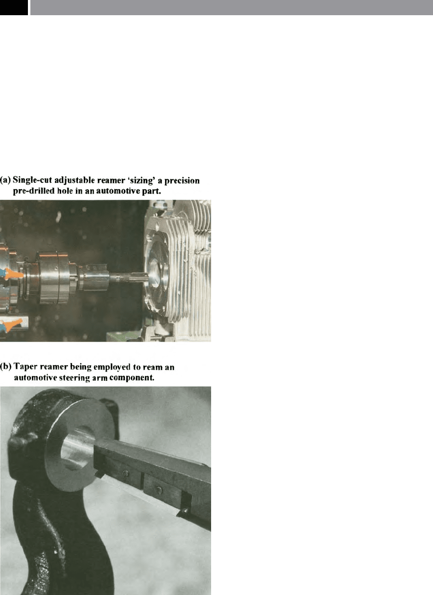
Figure 73. Reamers in action, reaming automotive parts.
[Courtesy of Shefcut Tool & Eng’g Ltd.]
.
140 Chapter 3