Smith G.T. Cutting Tool Technology: Industrial Handbook
Подождите немного. Документ загружается.

milling strategy decisions and frequently some com-
promises that must be made, in order to obtain the op-
timum cutter/workpiece engagement for a particular
machining situation.
Milling Cutter Density
In any face-milling operations the number of inserts
in cut (i.e. see Fig. 85), is a function of the quantity of
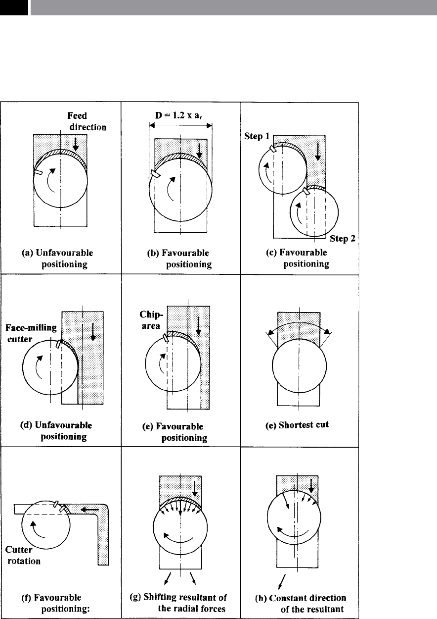
Figure 84. Face-milling cutter positioning over the workpiece – indicating favourable/unfavourable cut-
ter and workpiece placement – together with other important factors. [Courtesy of Sandvik Coromant]
.
162 Chapter 4

inserts around the cutter’s periphery (Z) and the en-
gagement angle (α). An expression for these milling
cutter inserts and the cutter diameter’s relationship is
derived [Source: Isakov – Kennametal Inc. and pub-
lished in American Machinist 1996)] from Fig. 85, as
follows:
α = 90° + α
1
sin α
=
AB
OA
=
W − .D
.D
=
(W − .D)
D
=
W − D
D
α
= arcsin
W − D
D
Z
c
=
Z(
�
+ arcsin W − D�D)
�
Where:
Z
c
(i.e. see the following footnote
18
)
D = Cutter diameter (mm),
W = Radial width of cut (mm),
α = Engagement angle (°),
α
1
= Angle between cutter centreline and cutter ra-
dius to the peripheral point of either exit, or entry (°).
is above formula, can be simplied to the following
relationship:
Z
c
= Zα/360
is engagement angle is dependent upon the radial
width of the cut (W) and the face-milling cutter’s di-
ameter (D). erefore, if the radial width of the cut
equals the cutter diameter (W/D = 1.0) and, the en-
gagement angle is 180°, then:
Z
c
= 180Z/360° = 0.5Z
18 ‘Z
c
’ represents the number of inserts in-cut, which can be
found for any cut width (W), by applying the above formula,
derived from the schematic diagram, illustrated in Fig. 85.
e values of ‘Z
c
’ can be obtained from the Table 7, for
various ‘W/D’ ratios, given below:
e face-milling cutter density must be such that
it allows the chip to correctly form and exhaust from
the cut. If inadequate chip space is provided, this will
result in the chip remaining in the chip gullet. is
lodged chip is then carried around and merging with
the succeeding chip and as a result, welding itself to it,
potentially causing cutting edge breakage and possi-
bly damage to the workpiece. In any cutter/workpiece
engagement, it is necessary to provide a cutting edge
density with at least one insert in-cut at all times. Fail-
ure to achieve this cutter density could result in severe
edge hammering, leading to one, or more of the fol-
lowing conditions: chipped cutting edges; a damaged
cutter; or excessive machine tool wear.
For ‘coarse-pitched’ milling cutters, having between
1-to-1.5 inserts per 25 mm of diameter, this will allow
for larger chip gullet spaces and as such, can be recom-
mended to be used on either: so workpiece materials
that produce continuous chips; or, for wide cuts with
a long insert engagement. Conversely, ‘ne-pitched’
milling cutters, with approximately 4-to-5 inserts per
25 mm of diameter, are normally utilised where lack of
insert engagement is a problem. ese milling cutters
having ‘ne-pitches’ , will allow at least one insert to
be in-cut at all times, even when machining very thin
workpiece cross-sectional areas. ese high-insert den-
sity milling cutters, are usually recommended when
machining high-temperature exotic alloys, or hard
steels – where light chip loads are taken. As a result of
the smaller chips, less chip gullet space is necessary, al-
lowing more inserts around the cutter’s periphery.
4.1.5 Peripheral Milling Cutter
Approach Angles – Their Affect
on Chip Thickness
As has been previously discussed, a multi-point tool
such as a milling cutter, will cut intermittently, as its
cutting edges repeatedly enter and exit the workpiece’s
arc of cut (i.e. engagement). It was suggested in the
previous section, that at least one, but preferably two,
Table 7: The ratio of cut width-to-diameter (W/D). Number of inserts in-cut Z
c
W/D: 0.88 0.80 0.75 0.67 0.56 0.38 0.33 0.19 0.125
Z
c
: 0.38 Z 0.35 Z 0.33 Z 0.30 Z 0.27 Z 0.21 Z 0.20 Z 0.14 Z 0.14 Z
[Source: Isakov – Kennametal Inc./pub. in American Machinist, 1996]
.
Milling Cutters and Associated Technologies 163
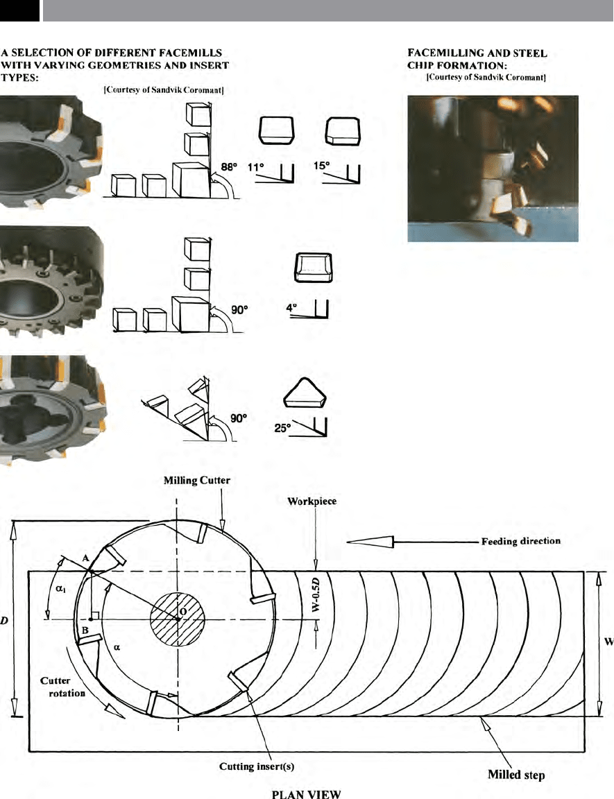
Figure 85. Typical facemilling cutters and their inserts, with a schematic representation of a milling cutter engagement angle
and the number of inserts in-cut. [Source: Isakov/American Machinist, 1996]
.
164 Chapter 4

cutting edges should be in-cut at all times. Tooling
manufacturers design and test their cutters during
engagement, carefully determining both the feed and
speed of a milling operation, ensuring that the cutting
forces are eectively balanced-out around all of the
teeth. e machining objective here, is to discover the
optimal chip thickness. As has been previously shown,
milling cutter utes can be either helical, or straight,
with the replaceable cutting inserts being located and
secured by either a wedge, or screw clamp. With each
adjacent cutting edge around the cutter’s periphery be-
ing referred to as its pitch. During a face-milling oper-
ation, a chip is formed at the two cutting edges, where-
upon, it slides up the tooth face and into the ute,
striking the llet, or rounded corner of this ute.
e approach angle is a key milling geometry fac-
tor, being formed the tool’s axis and by the peripheral
edges of either a solid cutter, or its cutting inserts. is
approach angle describes how far the top of the insert
inclines away, from that of being parallel to the cutter’s
axis (i.e. as shown in Fig. 83a). In most general milling
operations, the ‘approach’ ranges from 0° for creating
square shoulders (Fig. 83a-le), to 45° in nish-mill-
ing (Fig. 83a-right). Usually, milling cutter approach
angles ranging between 15° to 45° are the norm, with
a 15° approach enabling deeper cuts to be taken. As
the approach angle of the cutting edge inclination in-
creases, the chip becomes both longer and thinner for
the same D
OC
, or ‘a
e
’ (Fig. 83b), with the load being
spread over longer edge length – resulting in smoother
cutting. Larger insert inclination, enable higher fee-
drates to be employed, although it must be empha-
sised, with shallow cuts (Fig. 83a-bottom).
Taking a dierent milling operational premise, the
o
bjective when ‘rough-milling’ , is to remove the maxi-
mum workpiece stock in the shortest possible time.
e material removal rate being limited by the ‘avail-
able’ spindle power, although this condition can be op-
timised by ‘radial chip-thinning’
19
. e chip thickness
is based upon the calculated feed per tooth (f
z
) and it
diminishes as the radial width decreases and in reality,
creating a lighter actual ‘f
z
’. is ‘lessening eect’ of the
chip thickness, causes the cutting edges to rub, rather
than cut the workpiece material, as a result, the feed
per tooth (f
z
) should be increased as the radial depth
19 ‘Radial chip-thinning’ , is the eect of taking a radial D
OC
(a
e
)
of less than 25% of the milling cutter’s diameter.
decreases. is cutting strategy ‘boost’ in the eective
feed per tooth, provides the twin benets of longer
tool life, with shorter cycle-times.
For any operation in milling involving a ‘chip-thin-
n
ing exercise’ , of paramount importance is the cutter’s
approach/inclination angle (χ). erefore, as the ap-
proach angle (χ) become more inclined from say, 90°
to 45°, the chip thickness, its ‘h-value’
20
decreases (i.e. as
schematically-demonstrated in Fig. 83b). e optimal
chip thickness for a given set of cutting data, can be
entered into a machine tool’s CNC program, by utilis-
ing the following formula:
f
z
= h
m
/sinχ
e chip thickness (f
z
) is always constant, regardless of
the approach angle inclination, be it operated at 90°, or
down to 30°, or indeed, at a atter approach (see Fig.
83b). e exception to this ‘chip thickness rule’ be-
ing when utilising a round, or button-type insert (Fig.
83b-right), as it does not have either a top geometry, or
an edge chamfer, thereby creating the strongest type of
cutting edge. Round inserts without the straight cut-
ting edges associated with other milling inserts, cre-
ate chips that increase in thickness as the D
OC
becomes
deeper. Hence, for round inserts, the average chip
thickness (i.e. its ‘h
m
’ – value
21
), relates to the thickness
of cut this being based upon the insert’s radial engage-
ment of the workpiece via the milling cutter’s diam-
eter. If a comparison is made between a round milling
insert to that of an insert with a 90° approach (i.e. Fig.
83b-right and Fig. 83b-le, respectively), an identical
volume of chips will be removed for both at a set feed
20 ‘h-values’ , for a material group are represented as a range,
with a lower number being the starting value. For example, if
utilising a machining centre with a 35 kW spindle power avail-
ability for the milling of non-ferrous, or aluminium alloys,
the ‘h-value’ , or chip thickness ranges between 0.050 mm to
0.076 mm. Alternatively, using this same machine tool to mill,
either: stainless steels, titanium alloys, or heat-resistant super-
alloys, the ‘h-values’ will range from 0.076 mm to 0.152 mm,
whereas, for: plain carbon steels, cast-/nodular-cast irons the
range will be between 0.152 mm to 0.254 mm.
NB Do not attempt to mill thicker chips than is recommended
in the literature, as this action could result in over-loading the
cutting inserts and breaking their edges.
21 ‘h
m
value-ranges’ for various workpiece materials are identical
to those ‘h-value ranges’ previously mentioned.
Milling Cutters and Associated Technologies 165

per tooth and D
OC
. Although, if the D
OC
is half that of
the round insert’s inscribed circle, this round geom-
etry creates chips that are 30% thinner to that of the
90° approach inserts. is reduction in chip thickness
is the result of the round insert having a longer cutting
edge, which engages radially with the workpiece (Fig.
83b-right). Alternatively, if chip volume for both the
round and 90° approach inserts were identical, then
the chip length generated by the round insert is ap-
proximately 50% longer and it is much thinner than
its counterpart. Moreover, with the same feed for the
round insert, but the D
OC
is reduced so that it is 25%
of it’s inscribed circle, the chip thickness produced is
now 50% less for an identical chip volume. Hence, to
achieve the desired productivity benets that will ac-
crue from utilising a ‘chip-thinning strategy’ ,
the D
OC
needs to be <25% of the round insert’s inscribed cir-
cle. As the D
OC
has now become more shallow using
a round insert, the chip has now been ‘thinned’ , so in
order to compensate for this loss of stock removal, the
feedrate needs to be increased. erefore, as the round
insert’s D
OC
becomes more shallow the approach angle
attens-out to almost ‘innite length’. So, when the
average chip thickness and approach angle variables
are entered into the formula for ‘
feed per tooth’
22
in the
CNC program they can be signicantly higher – al-
most up to 100% greater.
In order to establish either round, or button-style
geometries for their ‘eective approach angles’ ,
the fol-
lowing formula has been derived:
‘Eective approach angle’ Tan χ = a
e
/(IC
e
/2)χ
Where:
χ = A
pproach angle (°),
a
e
= D
OC
(mm),
IC
e
= Inscribed circle – ‘eective’ (mm).
If a 90° approach angle is used, the rate of advance
per tooth equals the chip thickness. When there is a
decrease in the approach angle inclination, the chip
volume stays the same, but the length of cutting edge
engagement with the workpiece will increase. is re-
sults in a chip which is both smaller and longer than
that programmed, hence it is necessary to raise the
22 ‘Feed per tooth’ (f
z
), calculations will aect the chip-loading
for the milling cutter and be inuenced by the spindle power
availability – see previous equation for this relationship.
feedrate to increase the chip thickness to its required
level, when the D
OC
is less than the round insert’s ra-
dius. It can be said that although the chip created by
the round insert geometry has an almost identical chip
thickness to that of a 90° approach angled insert, the
button-style insert geometry removes workpiece ma-
terial at a considerably faster stock removal rate. e
only ‘down-side’ to that of utilising button-style milling
inserts, is the spindle power requirement is greater.
With increasing insert inclination of the approach
angles the chip thins, causing the cutting forces to be
re-directed. By way of an illustration of this eect, if a
45° insert approach is used, the axial force component
will be identical to that of the radial force. is radial
force component, tends to make the tool deect and
may generate chatter, conversely, the axial component
force is toward the direction of the spindle thereby re-
ducing the potential risk of its damage via vibrational
eects. erefore, if the insert inclination is such that
the approach angle is almost at, this has the advan-
tage of the axial force component being in the spindle’s
direction, this will minimise the likelihood of tool de-
ection. us the primary objective here, is to remove
workpiece stock at high rates and speedily, keeping the
approach angle low, with a light D
OC
, in this manner
allowing chips to be thin and as a result the cutter will
‘y’!
4.1.6 Spindle Camber/Tilt –
when Face-Milling
On some conventional and CNC milling machines,
the spindle can be tilted slightly
23
, this small inclina-
tion in the direction of the feed, ensures that the cut-
ter does not lie completely at to the workpiece’s sur-
face. is small spindle tilting technique avoids the
so-called ‘
re-cutting eect’
24
that normally if present
when utilising a large face-milling cutter. In reality, the
spindle camber is very slight and generally amounting
23 On many machining centres it is not always possible to tilt the
spindle and, in such situations, back-, recutting is an unavoid-
able milling surface texture condition.
24 ‘Re-cutting eect’ ,
this is the product of the cutting inserts
on the ‘back-edge’ of a large face-milling cutter scoring the
recently machined surface, thereby aecting and slightly
degrading the milled surface texture, while simultaneously
avoiding additional ank wear on the inserts – prolonging the
cutter’s life.
166 Chapter 4
to between 0.1 to 0.3 mm over a length of 1,000 mm.
When this is converted to angular measurements, this
equates to a value of between 20 to 60 seconds of arc
respectivly – as shown in the exaggerated diagram in
Fig. 86. Oen, when it is not possible to slightly tilt
the spindle, back-cutting problems can arise through
such factors as spindle, or workpiece deections. is
problem can be minimised by:
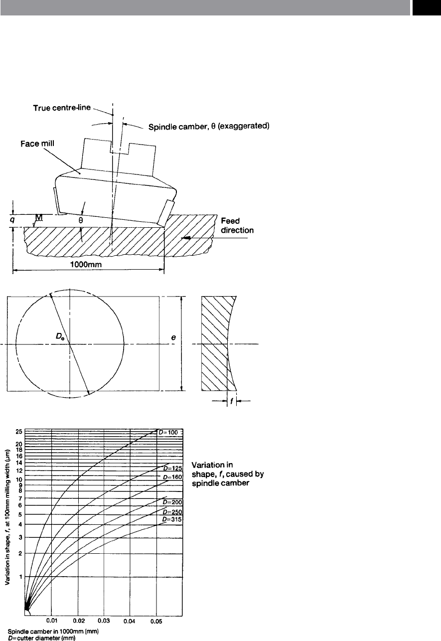
Figure 86. The inuence of spindle camber
(tilt) on the milled workpiece surface. [Courtesy
of Kennametal Hertel]
.
Milling Cutters and Associated Technologies 167

•
Improvements in workpiece support – ensuring the
both packing and clamping are sucient to support
the component,
•
Modifying the cutter to a positive geometry – this
has the eect of reducing any back-cutting milling
by the cutting inserts,
•
Reduction in cutting forces – though: feedrate re-
ductions, lighter D
OC
’s/cut widths, or by increasing
the cutting speed,
•
Modications to approach angles – this will have
the eect of reducing the axial force component,
•
Reducing spindle overhang – will decrease cutter
deection,
•
Inspection of cutter milling mounting – this will
ensure that any burrs, debris, or misalignments are
minimised.
If the spindle is slightly cambered when face-mill-
ing, a plain workpiece surface will not normally be
produced. Under these conditions of a slight camber,
the machined surface is normally concave, due to the
angular tilt of the milling cutter (i.e. shown in Fig. 86
top/middle schematic diagrams). e surface concav-
ity generated by this camber, depends upon the rela-
tionship between the: cutter’s diameter; width of the
workpiece surface being cut; together with the D
OC
.
e milled workpiece concavity ‘f’ , can be calculated
using the well-established Kirchner–Schulz formula,
as follows:
Milled concavity
f =
q
[D
e
� − (D
e
� − e
�)
]
Where:
f = Milled concavity (mm),
q = 1000tanθ where θ is the spindle camber (°),
D
e
= Eective diameter of the cutting circle (mm),
e = Width of workpiece surface being milled (mm).
Alternatively, a reasonable estimate of the milled con-
cavity ‘f’ can be obtained from the graph in Fig. 86
(bottom), that illustrates the variation in the concave
shape, for a variety of spindle cambers and face-mill-
ing diameters. ese concave surface modications
produced by the spindle camber are never large devia-
tions from the ‘true’ plane surface. For example, even
under the extreme conditions of employing a relatively
small diameter milling cutter of: φ100 mm; together
with a large spindle camber ‘q’ value of 0.05 mm, the
deviation in milled surface concavity only amounts to
25 µm over a workpiece width of 100 mm – this being
within the accepted tolerances for many commercial
situations. However, for the generation of high-pre-
cision milled surfaces, this minute level of concavity
would not be tolerated. In fact, when a milled surface
is metrologically inspected at high levels of magnica-
tion, the ‘surface topography’
25
consists of both form
and surface variations. ese form and surface varia-
tions are related directly to either the cutter-spindle ac-
curacy, or the axial displacement of the cutting inserts,
with the distance between wave crests (i.e. sometimes
termed the asperities – high points – on the machined
cusps) frequently coinciding with the feed per tooth. It
is possible to establish the reasons why a surface might
deviate from the ‘true’ plane, with some of the possible
factors being caused by:
•
Machine tool condition – possibly resulting from
the fact that the spindle bearings are in poor con-
dition, the slideways have appreciable ‘back-lash’
present, or poor ‘damping’ generating vibrational
tendencies – showing-up as ‘chatter-marks’ on the
milled surface,
•
Workpiece clamping/stability – if the workpiece is
not suciently and correctly clamped, then it could
ex, or move on the xture/pallet/table, whilst be-
ing machined, creating unwanted surface devia-
tions/uctuations,
•
Axial insert displacement – possibly created by
cutting inserts not precisely located in their respec-
tive pockets, or resulting from movement during
milling – due possibly to inadequate locking of the
insert in-situ during pre-setting,
25 ‘Surface topography’ , is a term that is oen used to describe
the form, waviness and surface texture uctuations from the
‘true’ plane. A machined surface may exhibit some, or all of
these variables, together with its ‘lay’.
NB Form errors are long-frequency components of a surface,
with waviness being medium-frequency components, while
surface texture is normally associated with short-frequency
components. Depending upon the relative size of the work-
piece, these variables are superimposed onto each other, but
each one can be ‘ltered-out’ by suitable magnication on
a Surface Texture Machine – for future analysis. e ‘lay’ is
the direction of the dominant surface pattern, created by the
passage of the cutter over the surface. When assessing a ma-
chined surface with a anisotropic lay condition – this being a
surface that has a signicant lay (i.e. clearly visible machining
marks), it is normal procedure to assess the surface’s condi-
tion at 90° to the lay.
168 Chapter 4

•
Insert wear uneven – possibly resulting from inad-
equate pre-setting of the cutting inserts – allowing
some to ‘stand-proud’ of the rest and as a conse-
quence, being subjected to higher wear than the
others,
•
Insert shape irregularities – possibly the result of
poorly manufactured cutting insert geometries,
creating diering heights once secured and accu-
rately positioned in their respective milling insert
seatings,
•
Irregular chip-ow – possibly the result of either the
insert chip-breakers operating inconsistently, or the
workpiece material having matrix inconsistencies.
4.2 Pocketing, Closed-Angle
Faces, Thin-Walled and
Thin-Based Milling
Strategies
Pocket Milling
In particular and in the aerospace industries, alumin-
ium machining from: wrought, extruded stock and
forged parts is a regular practice and, to a lesser extent,
this also occurs in many precision machining environ-
ments. Oen both for shallow and deep pockets and
for ribs, it is necessary to relieve weight at critical sec-
tions on components.
One of the oldest established techniques for achiev-
ing pocket features, is to drill a hole at the centre of the
pocket to a pre-set depth. en change tools and plac-
ing the milling cutter in this hole clear-out the pocket,
repeating this cycle until the pocket is ‘roughed-out’.
Perhaps changing cutters and taking nishing cuts to
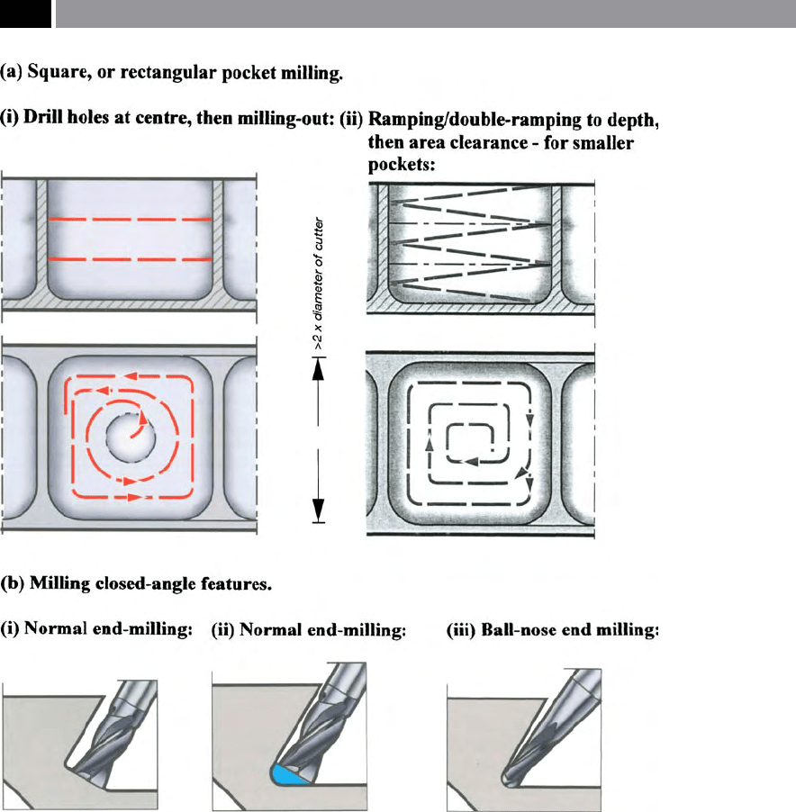
complete the feature (Fig. 87ai). Rather than simply
plunging to depth with the cutter, ramping-down into
pockets is an eective way of reaching the ‘rst-level’
for the pocket’s area clearance. Both ramping and
‘double-ramping’ (i.e. this latter technique is particu-
larly ecient for smaller pocket dimensions), are ways
o
f removing stock via a ‘diagonal plunge’ , while tak-
ing the milling cutter to its required depth (Fig. 87aii).
is technique is an ecient machining strategy for
the milling of square and rectangular pockets – for
high stock removal.
If the pocket is of non-uniform dimensions, then
perhaps a ‘lace’ ,
or ‘non-lace’
26
cutter path clearance
technique might be the preferred option, when having
to machine these type of component features.
Milling Closed-Angle Faces
For the machining of so-called ‘closed angle features’
such as a re-entrant pocket
27
, or ‘dovetail’
28
, these latter
features are typically utilised for drop-forging inserts.
In Fig. 87bi, the pocket has a land (i.e. to impart ad-
ditional mechanical strength to the corner), this land
which would run around the base of the enclosed
pocket, requiring a 5-axis machining centre
29
to com-
plete the milling operation. In Fig. 87bii, a normal end
mill cannot remove the excess material le in the base of
the re-entrant angle, necessitating either a ball-nosed,
or tapered ball-nosed cutter to reach in and mill the
desired feature (Fig. 87biii – in this case, the illustra-
tion shows a tapered ball-nosed milling cutter).
26 ‘Lace’ , or ‘non-lace’ cutter path, a ‘lace-cut’ is where the cutter
clears (i.e. machines) an area with cutter paths that step-over
at regular pre-dened intervals, normally used when a sur-
face has regular dimensions, such as a square, or rectangular
feature. Conversely, a ‘non-lace’ cut is normally reserved for
the machining of irregular surfaces with the tool paths being
non-linear in their step-over paths, for example, when milling
a triangular-shaped pocket/feature, or similar.
NB With the advent of sophisticated Computer-aided Manu-
facture (CAM) programming capabilities, much of the auto-
mated generation of cutter paths, decision-making is under-
taken by the soware, to optimise area clearances for these
component features.
27 ‘Re-entrant pocket’ ,
is one where the base of the pocketed fea-
ture is somewhat larger than its top, meaning that the pocket
faces slope inward.
28 ‘Dovetails’ ,
are normally open at both ends allowing the male
dovetail on the part to be held and its tapered key to easily
inserted, positioned and locked in-situ. Usually, such features
are generated and formed on machine tools such as: Plano-
mills, Shapers, etc., but where such equipment is not available,
then a ‘closed-angle milling’ operation is necessary.
29 5-axis Machining Centre, normally has 3 linear (i.e. X, Y and
Z) and 2 rotary (i.e. A and B) axes. e relationship of the
rotary axis will depend upon the machine tool’s congura-
tion, but they allow axis of a milling cutter into an otherwise
closed-feature, negating the possibility of any cutter/spindle
fouling on the workpiece.
Milling Cutters and Associated Technologies 169
Milling Thin-Walls
For the machining of thin-walls (Fig. 88), such as
when milling rib-sections on aerospace components,
the machining strategy will vary, depending upon the
respective height and wall thickness. In every case of
thin-walled machining, the number of passes will be
determined by the component’s wall dimensions and
axial depth of cut, in the following manner:
•
Height-to-thickness ratios of <15:1 – then possibly
the most favoured milling strategy is to machine
one side of the wall in non-overlapping passes, fol-
lowed by a repetition on the remaining side – as
depicted in Fig. 88a. In all cases of thin-walled ma-
chining a ‘nishing allowance’ is le on both sides
and the base for subsequent machining,
•
Height-to-thickness ratios of <30:1 – there are two
basic milling techniques that are usually employed,
these are:
•
‘Waterline milling’ (Fig. 88b-le) – this is where
either side of the thin-wall feature is milled to pre-
determined depths, in non-overlapping passes,
Figure 87. Pocket and closed-angle feature milling. [Courtesy of Sandvik Coromant].
170 Chapter 4
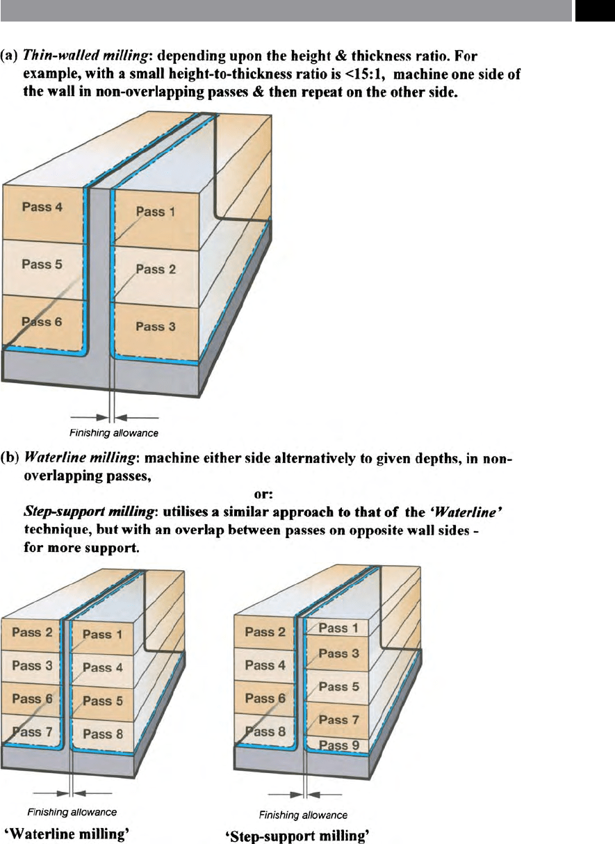
Figure 88. Thin-walled machining strategies. [Courtesy of Sandvik Coromant].
Milling Cutters and Associated Technologies 171