Smith G.T. Cutting Tool Technology: Industrial Handbook
Подождите немного. Документ загружается.

tion, which is determined by how deep the periph-
eral cutting insert’s edges cut, with the insert’s faces
on the edge of the cutter generating the nished
workpiece surface.
•
Peripheral milling – radial (Fig. 78) – utilises pe-
ripherally-located cutting edges that are situated in
a milling cutter body which is horizontally spindle-
mounted. e cutter rotates around a horizontal
axis, this axis being parallel to the tangential feed-
ing direction. Peripheral milling has a D
OC
in a
radial direction that will determine how deep the
cutter’s diameter will penetrate into the workpiece.
ere are two peripheral milling strategies that can
be used with these horizontally-mounted cutters,
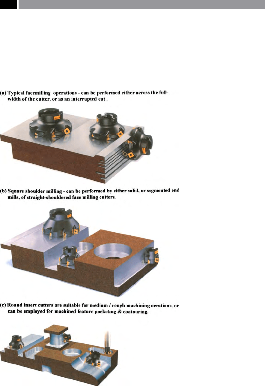
Figure 77. Just a few of the ma-
chined features that can be produced
by a range of face milling cutters.
[Courtesy of Sandvik Coromant]
.
152 Chapter 4
these are either ‘Up-cut’ (Fig. 78 top-right denoted
‘U’), or ‘Down-cut’ (Fig. 78 top-le denoted ‘D’)
7
milling operations – more will be said on this topic
shortly.
•
Peripheral milling – tangential (Fig. 79) – allows
the cutter to not only face mill, but has the capabil-
ity to work along a third direction feed – axially (i.e.
downward into the part’s surface – Fig. 79 – top).
Essentially, this milling operation is a form of drill-
ing, being performed by the cutting edges on the
cutter’s face, oen termed ‘slot-drilling’
8
. is tech-
nique allows the cutter – perhaps ground with radi-
used indexable cutting inserts (i.e. see Fig. 79b), to
machine open and closed pockets, or slots, enabling
the cutter’s peripheral edges to complete a range of
cutter-paths to open up the a rectangular, or irregu-
lar ‘
pocketed features’
9
in the workpiece (Fig. 79a).
Up-Cut and Down-Cut Milling
Here (Fig. 78), the workpiece is fed into the horizon-
tal-mounted peripheral milling cutter, which has its
rotation either clockwise (i.e. termed ‘down-cut mill-
7 ‘Up-cut’ and ‘Down-cut milling’ , these two peripheral milling
techniques are sometimes referred to as either: ‘Conventional
milling’ , or ‘Climb-milling’ operations, respectively.
8 ‘Slot-drilling’ ,
normally utilises two cutting edges on the
cutter’s face. One cutting edge being longer that the other
– crossing the cutter’s centreline, thus as it rotates, its dissimi-
lar length of cutting edges will sweep across the total area of
cut. is action, allows the cutter to be plunged-down into the
workpiece’s surface and then feed along – to produce a slot
– hence the name: ‘slot-drill’.
NB If the slot-drill has its cutting edges rounded (i.e. radiused),
a ‘Ball-nosed slot-drill’ will result, and such a cutter geometry
can produce a range of ‘blended/curved’ workpiece features,
allowing complex-curved proles (i.e ‘sculpture-milling’) op-
erations to be undertaken. In some cases, the curvature of the
radius is modied (i.e. in the case of an ‘APT tool’ – meaning:
automated-programmed tool) geometry is ground, to mini-
mise step-over/cusp height eects, when (post) nishing-o
operations are more speedily rendered on complex-curved
workpiece features. For example, when completing the high-
quality nishing operations on moulds and dies.
9 ‘Pocketed features’ (Fig. 79a), these operations can be gener-
ated by feeding the cutter to a pre-determined series of suc-
cessive depths these being consecutively opened-up by a range
of tool-path strategies. Typical of the techniques for such
pocketing cutter path control, is to employ either ‘Lace-’ ,
or
‘Non-lace cuts’ – more will be said on this later.
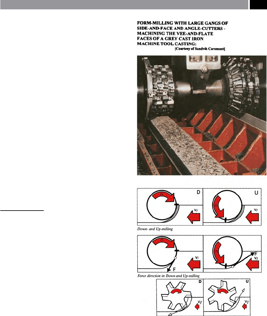
Figure 78. Peripheral milling (radial), can be undertaken by
either: up- or down-cut milling operations
NB These dierent milling cutter rotational directions, impart
totally dissimilar resultant force vectors whilst machining, play-
ing a signicant role in the attendant: power consumption fac-
tors, resultant machined workpiece residual stresses and sur-
face inegrity present, together with geometric shapes/types
of workpieces that can be succesfully machined. [Courtesy of
Sandvik Coromant]
.
Milling Cutters and Associated Technologies 153
ing’ – Fig. 78 top-le ‘D’), or anti-clockwise (‘up-cut
milling’ Fig. 78 top-right ‘U’). Hence, the workpiece is
fed either with, or against the milling cutter’s rotation
direction, which determines the nature of the begin-
ning, or completion of the cut.
In ‘down-cut milling’ (Fig. 78 top-le), it can be
seen that the workpiece direction of feed is the same
as that of the cutter’s rotation, in the vicinity of the cut.
In such circumstances of peripheral milling concern-
ing the milled chip’s area, the chip thickness begins
to decrease from the initiation of the cut, eectively
reaching zero on completion of the insert’s peripheral
rotation, prior to the adjacent cutting insert continu-
ing this trend in chip development. Furthermore, as
each milling cutter insert enters the cut with a large
chip thickness, this avoids any potential rubbing and
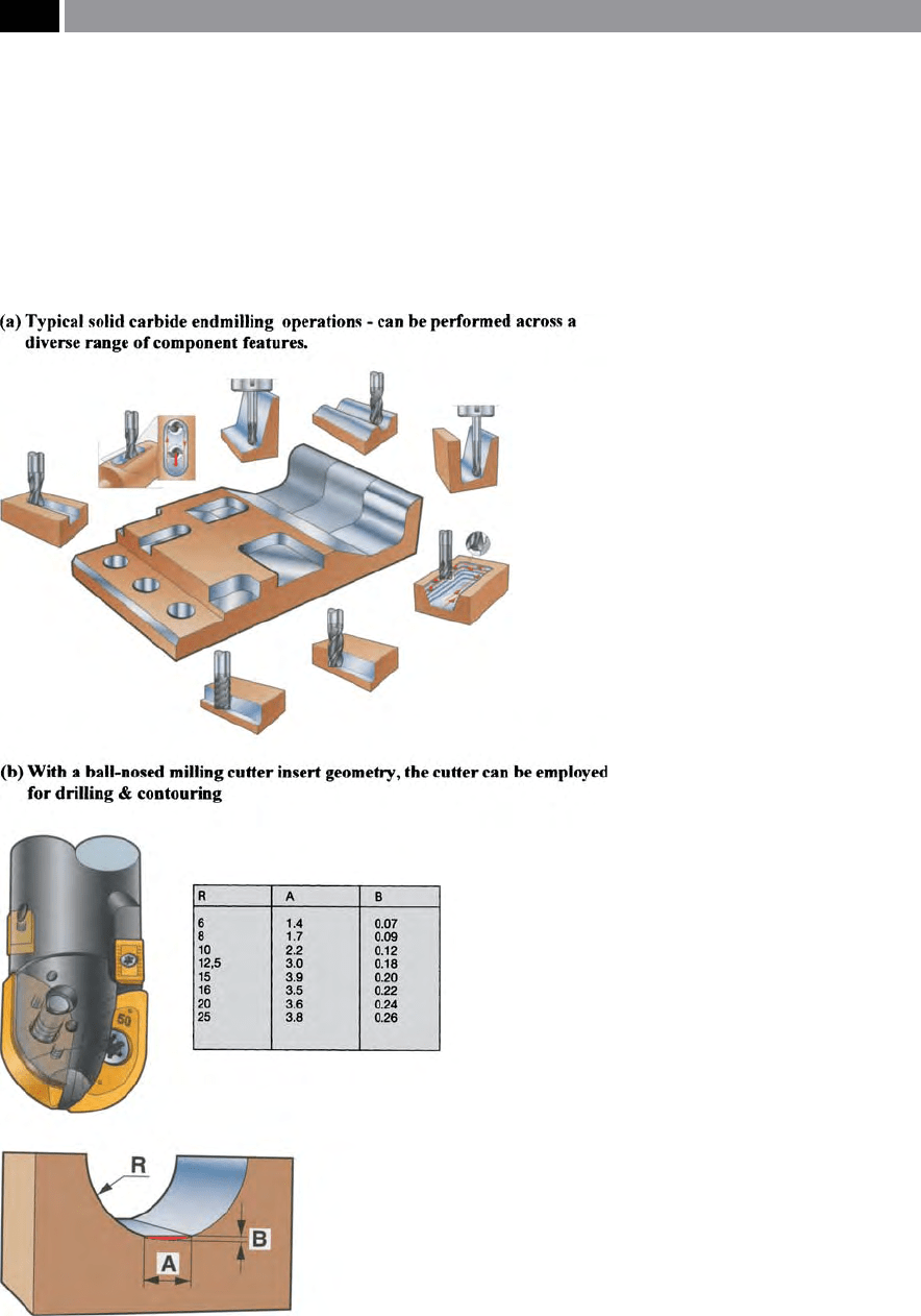
Figure 79. Axial feed milling using
either: solid carbide end mills, slot drills,
or a ball-nosed milling cutter
NB These type of milling cutters can be
widely utilised across a vast range op po-
tential workpiece geometrically-shaped
features. [Courtesy of Sandvik Coromant]
.
154 Chapter 4

the likelihood of workpiece surface burnishing, mini-
mising both the probability of temperature increases
and work-hardening tendencies. As a cautionary note,
although this is a very eective and ecient way of
peripheral cutting, if any ‘back-lash’
10
is present, then
the cutter will attempt to ‘snatch’ ,
or at worst, ‘ride-
over’ the workpiece’s surface, as it is pulled-into the
cut. is possible ‘snatching-eect’ ,
being created by
the resultant cutting force tending toward a back-ward
direction (Fig. 78 middle-le). is adverse action, re-
sulting from presence of ‘back-lash’ could even cause
cutter, or spindle damage, together with part scrap-
page, if it is not minimised/eliminated.
In ‘Up-cut milling’ (Fig. 78 top-right), the work-
piece feed direction opposes that of the milling cutter
rotation, within the cutting vicinity. erefore, the
chip thickness commences at zero and increases as it ap-
proaches the exit point, at the end of the cut. Due to
the fact that at the initiation of the cutting sequence
the cutting edge has no eective forces acting on it,
so it must be forced into the cut and during this time,
some eects of rubbing/burnishing create excessive lo-
calised friction, which in turn, results in an increased
temperature. Here, contact with the workpiece mate-
rial from the previous insert can work-harden the sur-
face. Yet another disadvantage of utilising ‘Up-cut mill-
ing’ ,
is that the resultant force (Fig. 78 middle-right)
can attempt to li the workpiece on the machine tool’s
table, therefore it must be securely clamped/xtured
into place.
e machine tool’s spindle power will depend on
the either the feed force (V
f
), or the resultant force
10 ‘Back-lash’ , is a problem concerning slideway ‘oat’ (i.e.
slight, but unwanted lateral uncontrolled back-and-forward
motion) in the machine tool’s leadscrew, or ballscrew. On
conventional milling machines (i.e. with no CNC-controlled
axes), these are normally equipped with an Acme thread (i.e.
having a truncated Vee-form thread of 29° included angle),
they require a ‘Back-lash eliminator’ to be tted, which when
rotated/tightened on the split-nut assembly surrounding the
Acme thread which is mechanically-connected to the work-
piece’s table, reduces any back-lash present – thereby allowing
down-cut milling to be successfully performed.
NB Ballscrews, are usually tted to CNC-controlled machine
tools, as they can be pre-loaded by the machine tool builder,
thus minimising any potential back-lash problems. It is nor-
mally desirable to use down-cut milling techniques in CNC
machining, as it is more ecient cutting technique, in com-
parison to that of up-cut milling.
component, the relationship of these ‘Up- and Down-
cut milling’ factors being schematically illustrated in
Fig. 78 – bottom diagrams. is resultant force is a
combination of the tangential and radial cutting forces.
e resultant cutting force will dier signicantly in
its vectored angle, depending upon the cutter position
relative to that of the workpiece’s. ese vectored angles
(Fig. 78 – bottom diagrams), will become larger with
increased D
OC
– for ‘Up-cut milling’ , the net eect be-
ing that the milling process needs more spindle power.
In ‘Down-cut milling’ ,
due to the fact that the resultant
force is in the same direction to that of the feed, it will
signicantly reduce the feed power requirement. Yet
another advantage of using a ‘Down-cut milling’ strat-
egy, is that there will be no reverse change of direction,
so any workpiece clamping is simplied.
4.1.2 Milling Cutter Geometry – Insert
Axial and Radial Rake Angles
With any machining operation, the combination of
the rake and clearance angles determines the cutting
edge’s wedge angle, this greatly inuences the insert’s
strength. Oen, cemented carbide cutting inserts have
a small negative primary land present, this helps to
avoid fracture during the intermittent cutting action
associated with a milling operation. A helix angle is
present on many milling cutters
11
, be it a: side-and-
11 Helix angles, can vary considerably, the helices being selected
for the workpiece material to be cut. For example, when mill-
ing aluminium, a quick helix is necessary to take advantage of
the low shear characteristics of the material, conversely, when
milling grey cast iron a slow helix is preferable, as this mate-
rial is somewhat brittle in nature. In many instances when ma-
chining the so-called ‘sticky’ materials such most aluminium
grades, etc., then the milling cutter is designed to have a larger
‘chip-gusset’/‘chip-pocket’ (i.e. clearance space for the chip).
is larger ‘chip-pocket’ may take the form of alternating the
bias of the helices for the cutting edges on say, a peripheral
milling cutter, having a positive helix on one tooth, with the
adjacent tooth being of negative helix – typically a milling
cutter of this design is the so-called: ‘staggered-toothed side-
and-face cutter’.
Milling Cutters and Associated Technologies 155

face cutter, face-mill, end mill
12
, slot-drill, etc. e
helix angle brings the cutting edge progressively into
c
ut, resulting in ‘quieter running’ , but instead of an
orthogonal cutting action (i.e. with two component
forces – tangential and radial – acting on the cutting
edge), an oblique cutting action occurs (i.e having an
additional axial force component present). is axial
force component resulting from the geometry of the
helix, has a tendency to either ‘pull’ the cutter out of
the spindle, or push it towards it, depending upon
whether it is of a le- or right-hand helix.
For all of the designs for Endmills and Slotdrills
currently available, there are basically three types of
axial and rake angled cutting edge geometries, theses
are:
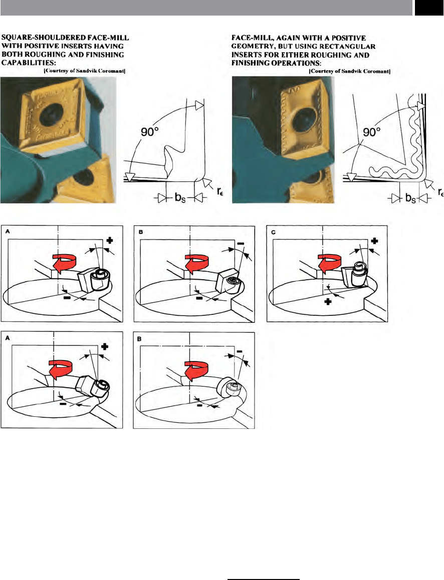
•
Double-positive cutting edges (i.e shown in Fig.
80C) – normally employs a single-sided insert,
as this geometry allows a relatively ‘free’ cutting/
shearing action. Here, the positive axial and rake
geometries, produce low cutting forces, owing to
the reduced chip thickness and a shorter length of
contact at the chip/tool interface. As a result, less
spindle power is necessary, enabling a lower insert
strength requirement enabling high-shear cutting
availability, when compared to either of the fol-
lowing insert geometries. e manner in which
the chip formation occurs is benecial, in that spi-
ral chips are formed, which can easily be broken
and exhausted from their respective chip pockets.
When milling ductile materials such as grades of:
aluminium, steel, as well as some stainless and heat-
resistant steels, where there is a tendency to form
BUE, the double-positive geometry is the only suc-
cessful solution to machining such workpiece ma-
terials. If the workpiece has a tendency to be some-
what unstable, perhaps due to either its fragility, or
12 ‘Endmills’ , can not only have the cutting edges designed with
a helix angle, but for the ‘solid’ end-milling varieties, they may
have either their cutting edge land lengths interrupted by a
groove this feature being a long-lead spiral groove – to act as
a form of chip-breaker (i.e. they are oen called ‘Rippa-cut-
ters’ – utilised for high stock removal rates), for long-chipping
materials. For some cutter designs, such as: ‘Roller-, or Slab-
mills’ , they can have cutting inserts staggered along the tool’s
periphery covering the length of the body, to disrupt the long-
chipping swarf (i.e. see Fig. 76). For Endmills versions of this
inserted-toothed design, they are oen termed ‘Porcupine
cutters’ (i.e. an example of a ball-nosed version, is depicted in
Fig. 79b).
clamping method, then the double-positive insert
geometry is once again, the most suitable milling
geometry to use.
•
Double-negative cutting edges (Fig. 80B – shown
here with either a round insert – bottom-le, or
square insert – top-right) – in this case, the radial
and axial angles are both negative. When a double-
negative insert is used, the required clearance is ob-
tained by tilting the insert. is ‘tilt’ of the insert,
has the added economical benet of allowing both
sides of the insert to be utilised, enabling the avail-
ability of more cutting edges coupled to stronger
edges, when compared to the former insert geom-
etry. is double-negative milling cutter insert ge-
ometry, is most suitable for machining conditions
involving heavy impact stresses, associated with
workpieces produced from: hard steels, certain
cast iron matrices and on some of their ‘chilled-sur-
faces’
13
, or ‘induction-hardened surfaces’
14
– nor-
mally using the ultra-hard PCBN-grades of inserts.
With these ‘Double-negative’ insert cutting geom-
etries, the demands on spindle power requirement
and its stability are considerable, owing to the large
cutting forces and chip thickness factors associated
with this type of geometry.
•
Positive/negative cutting edges (Fig. 80A – illus-
trating a square insert – top-le, or an inclined
and chamfered square insert – middle-le). For ex-
ample, in the case of Fig.79a (top-le), the insert
13 ‘Chilled cast iron surfaces’ , are used in order to produce a
hard-wearing surface, this being necessary for example on the
Vee-and-at slideways’ for cast lathe beds. Here, a ‘chill’ (i.e.
normally a metallic interface) is for example strategically-po-
sitioned in the cavity, prior to pouring the liquid melt. is
‘metallic chill’ acts as a ‘heat-sink’ to quickly allow solidica-
tion at the liquid/wall interface, producing a high tempera-
ture/cooling gradient and subsequent crystalline growth of
small grains, that have become both locally hard and wear re-
sistant, but are surrounded by a graphite-based matrix that of-
fers excellent ‘damping’ qualities to the overall cast structure.
14 ‘Induction-hardened surfaces’ ,
are usually obtained by a trav-
elling electric resistance induction heating/cooling unit. is
equipment, once it has locally heated the surface, will be im-
mediately quenched*, as the apparatus slowly moves along the
required surface to be heat-treated, imparting a surface-hard-
ened layer to the cast iron.*is induction-hardened surface
now consists (i.e. metallurgically) of a very hard ‘white-iron’ ,
appearance – aer suitable metallographical preparation
– with a white surface layer, once it has been suitably acid-
etched.
156 Chapter 4
geometry comprises of a combined positive axial
angle and a negative radial angle. Although the ba-
sic form of the insert may have a negative geometry,
the edge on its end face must be positive in order to
give a positive axial rake. e spindle power require-
ments for this combined geometry are a compromise
between the lower demands of the double-positive
insert geometry and the higher ones associated
with that of its double-negative counterparts. With
this positive/negative milling insert geometry, high
feeds per tooth combined with large D
OC
’s can be
achieved, because the negative radial rake provides
high insert strength, whilst the positive axial rake
oers good chip formation, with the added bonus
of directing the chips away from the cutter body
15
.
For any general-purpose milling applications, the
cutters having positive/negative cutting insert ge-
ometries are usually ideal.
15 ‘Chip-evacuation/-exhaust’ , are terms that are readily used to
explain how the chips are removed from the milling cutter’s
body. It is a very important consideration, as any chip-jam-
ming tendencies must be avoided at all cost, as the cutter,
workpiece, or both, can be severely-damaged if this potential
and avoidable problem arises.
Figure 80. The rake and clearance angles for various types of face-milling cutter insert geometries. [Courtesy of Sandvik Coro-
mant]
.
Milling Cutters and Associated Technologies 157
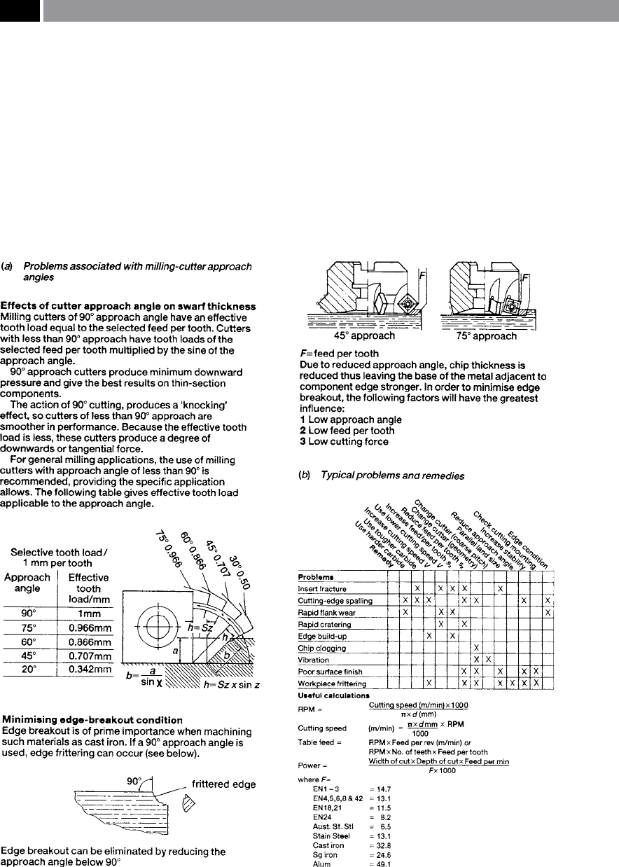
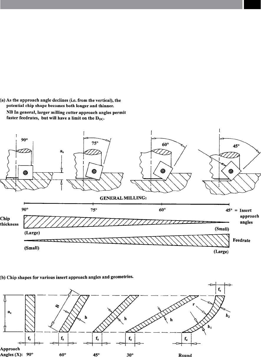
4.1.3 Milling Cutter – Approach Angles
Although cutting insert axial and radial rake angles
are important to correctly select, probably of similar
importance is the milling cutter’s approach, or enter-
ing angle (i.e described and illustrated in Fig. 81).
e insert’s inclination can vary by pre-selecting the
most suitable one for the workpiece to be milled. Of-
ten a compromise has to be made when selecting the
cutting insert’s inclination/approach angle. For ex-
ample, inserts having an approach angle of 90°, are
termed ‘Square-shoulder cutters’ (i.e. depicted in Fig.
83a – le), as their name implies, they are normally
utilised when machining up to a shoulder, or perhaps
a stepped-feature on the workpiece. ere are some
problems associated with 90° approach angled milling
cutters, their limitations are:
•
Chip thickness is at a maximum – for a given
feedrate, resulting in high loads on the cutting in-
serts,
Figure 81. Face milling cutter insert approach angles. [Courtesy of Stellram].
158 Chapter 4
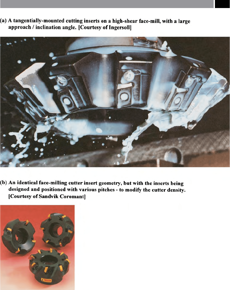
Figure 82. Face-milling cutters, having inclined approach angles, with either high-shear (i.e. tangentially-mounted) inserts, or
cutter insert density variations. [Courtesy of Ingersoll, Courtesy of Sendrik Coromant]
.
Milling Cutters and Associated Technologies 159

•
Chip ow may be hampered – the vectored angle
for exhausting chips may be compromised,
•
High radial force component
16
– i.e. in relation to
the axial force, produces unfavourable loads on the
spindle, creating vibration tendencies, hence the
feeds must be restricted,
•
Positive geometry triangular inserts should not be
used – these weaken insert corners, whereas rhom-
boid-shaped insert geometries, or similar, oer
much stronger insert cutting edges.
For general-purpose milling operations, intermedi-
ate approach angles such as inserts having an 75° ap-
proach are common (i.e see Fig. 82a), as they provide
good edge strength in combination with a favourable
relationship between insert size and cutting depth.
Moreover, if these 75° approach-angled inserts are
tangentially-mounted (i.e. as depicted in Fig. 82a), the
edges are even stronger because of the ‘body’ of the in-
sert is more fully-supported, than is generally the case
for most of the radially-mounted variants. Equally, an
insert with an 45° approach angle, will spread the load
over a longer cutting edge (Fig. 83b). is 45° insert
approach geometry, provides good chip-ow for long-
chipping materials, with a low radial force component
in comparison to that of the axial force, what is more a
strong insert edge allows higher feedrates to be utilised
(Fig 83a).
When roughing-cuts are necessary, or dicult-to-
machine workpiece materials must be milled requir-
ing strong insert edges, then a round insert might be
the answer. In general, round inserts have a positive
geometry with no sharp edges and as a result, oer
very strong cutting edges and chip-loads are relatively
evenly distributed along the rounded contact region
(Fig. 83b – right). Furthermore, a round insert usu-
ally has a positive insert geometry, which can then be
turned in its seating to simply provide additional cut-
ting edges.
16 ‘Square-shoulder cutters’ , can produce a high radial force
component, which means that feedrates must be limited, as
they may cause ‘edge frittering’ (i.e. see Fig. 81 – bottom le,
illustrating an edge break-out condition), this unacceptable
machining condition is particularly prevalent on brittle-types
of workpiece materials, such as: (most) Brasses, (many) Cast
irons, (some) Powder Metallurgy compacts, together with
(many) non-metallic materials – Plastics, Perspex, Tufnol,
Carbon-bre, etc.
4.1.4 Face-Milling Engagement –
Angles and Insert Density
Face-Milling Engagement
In any milling machining operation involving the po-
sitioning of the cutter in relation to a workpiece, some
thought should be given to not only the cutter’s: diam-
eter; number of teeth, or cutting inserts; width of the
workpiece; but also how the resultant cutting force(s)
might inuence the overall eectiveness of the pro-
duction process. is latter point, not only inuences
method of component clamping, dictating: how, where
and what will be the optimum method of ‘location and
restraint’
17
of the workpiece, but on exit from cut, the
sudden disengagement and release of cutting forces
will potentially create not only a exit-burr on ductile
materials, or frittered edge on a brittle material. e
cutter’s exit can inuence the type of stress induced
into the workpiece surface – a compressive stress be-
ing preferred (more will be said on this topic later, in
the section dealing with ‘Machined Surface Integrity’).
In most milling operations the term: ‘engagement’ con-
cerns the relationship of cutter-to-workpiece position-
ing and, in virtually all face-milling operations, one
tries to prevent at the exit of the cut, the chip being at
its thickest, as this is an unfavourable machining strat-
egy. e objective when milling, is to always try to get
the thinnest possible chip at exit from the cut. Some
of these engagement positioning relationships are de-
picted in Fig. 84, indicating where the most favourable
cutter/workpiece relationships are present. Also in
Fig. 84, are depicted some unfavourable engagements
that should be avoided, this may be possible by either
changing the milling cutter’s diameter, or its tool path
if possible, to avoid such engagements.
e milled cut length is inuenced by the position
of the cutter with respect to the workpiece, with tool
life being related to each cutting insert’s amount of
time engaged in the actual cut. For example, in Fig.
84g, a cutter has been positioned centrally over the
workpiece, this produces the shortest possible time
17 ‘Location and restraint’ , are important factors when work-
holding. A component needs to be not only accurately located
with respect to either a ‘datum’ , or held on a ‘grid-plate’ in a
known relationship to that of the cutter’s position, but it must
also be properly restrained – to prevent any, compliance of
its ‘degrees of freedom’ while it is clamped during machining.
Hence the term: ‘Location and restraint’.
160 Chapter 4
in-cut, conversely, in Fig. 84h the cutter has been
moved just o-centre, causing a longer arc of cut for
each insert, which is likely to reduce the tool’s ‘cutting
life’ somewhat, but this is only part of the problem of
o-centre cutting. Returning to the cutter positioned
centrally (i.e. Fig. 84g), here the direction of the radial
component cutting forces will uctuate, with respect
to the cutting edges start and nish cutting, which
may create potential vibrational problems, or prema-
ture edge breakdown. However, with o-centre mill-
ing (i.e. Fig. 84h), this machining strategy introduces
a constant force direction, moreover, as the cutter is
positioned not quite centrally over the workpiece, this
central region produces the largest average chip thick-
ness. Just to complicate matters still further, if the cut-
ter is positioned even further o-centre, this will allow
even more inserts to be simultaneously brought into
c
ut (i.e. shown as ‘α’ , in Fig. 85). ere are oen many
Figure 83. The importance of cutting insert approach angle inclination on the resultant chip shape. [Sources: Fig. a: Tooling
University, 2003; Fig. b: Heuwinkel & Richter, 2005]
.
Milling Cutters and Associated Technologies 161