Shani G. Radiation Dosimetry: Instrumentation and Methods
Подождите немного. Документ загружается.

460 Radiation Dosimetry: Instrumentation and Methods
and in accelerator applications. The Neutrometer
TM
is a
pen-sized tube partially filled with a superheated drop
composition. Neutrons impinge on the superheated drops,
causing them to vaporize suddenly. The resulting bubbles
push a piston up a calibrated tube, giving a direct indica-
tion of the neutron dose equivalent. The Neutrometer
TM
can be reused for several successive exposure periods,
with each exposure adding an increment to the total accu-
mulated dose. The Neutrometer
TM
-HD is designed for
higher dose ranges. Vials containing the superheated drop
composition are placed at various locations in the irradi-
ation area, such as near a high-energy medical accelerator.
Bubbles that are nucleated by neutrons force an indicator
liquid up a calibrated pipette. This displacement gives the
neutron dose equivalent. The spatial dependence of the
dose equivalent can therefore be measured immediately,
without recourse to activation foils, scintillation powders,
or other similar systems that require extensive post-pro-
cessing. Tests to characterize the performance of these
detectors suggest that they are nearly dose-equivalent, that
batch-to-batch uniformity is good, and that they meet many
of the demands required in their respective applications.
The personnel neutron dosimeter, Neutrometer-100,
is 12.5 cm tall and weighs 10 g. The round glass tube
which holds the superheated drop composition is held in
a triangular plastic holder. The bottom section holds
approximately 0.5 ml of aqueous gel composition with
approximately 8000 drops of 100-
m diameter. Atop this
composition is a gel piston, a white disc (which is what
is measured against the calibrated scale), and a small
amount of gel which acts as a lens so that the scale is
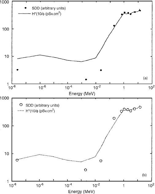
magnified. The SDD-100 drop material has been charac-
terized in the energy range 0.2 to 14 MeV for thermal
energies and at 2, 24, and 144 keV. The energy response
is shown in Figure 10.53a, compared with the fluence to
ambient dose-equivalent conversion factor. In Figure
10.53b, two modifications have been made. The albedo
response of the detector has been estimated, comparing it
with the fluence to individual dose-equivalent, penetrating,
conversion factor. The contribution due to n-capture
gamma-rays has been subtracted, from this factor, show-
ing better agreement with the estimated albedo response
based on measurements.
It was found that the displacement of the piston, d in
mm, fits the following depletion equation (l0%):
(10.48)
where
D is the neutron dose equivalent in mSv. The prac-
tical limit of the neutrometer was 57 mm, corresponding
to 8 mSv. The smallest calibration mark on the scale
corresponded to 0.9 mm for a dose equivalent of 50
Sv
(5 mrem). The calibration factor used in the results was:
where V is the volume displacement of indicator liquid in
the pipette, in ml.
VI. SOLID-STATE NEUTRON DOSIMETER
Solid-state detectors were very limited in their use for
neutron detection. The main reasons were: (a) neutron
radiation damage to the crystal made the detector useful
only for a short period of usage (a small number of total
counts) and (b) solid-state detectors were relatively too
expensive for uses as described in (a). In the last few years,
the manufacturing technique of solid-state devices has
developed tremendously. Many different kinds of devices
are available on the market for a low price. Radiation
damage to the device is not a problem when neutron
dosimetry is the concern, because the dose is measured
by the damage caused to the detector. A change in resis-
tivity or leakage current in the device is a measure of the
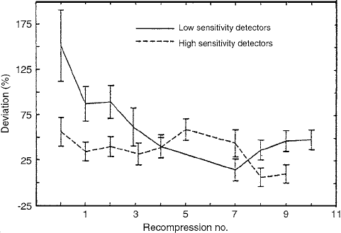
FIGURE 10.52 Deviation of the dose equivalents measured with bubble detectors from the dose equivalent as a function of the
recompression cycles. Irradiation was done with an Am-Be source. (From Reference [41]. With permission.)
d 65 1 e
0.27D
()
Dose equivalent (mSv) 21.5 1 1.37 V()ln
Ch-10.fm Page 460 Friday, November 10, 2000 12:04 PM
Neutron Dosimetry 461
dose absorbed in it. These are just a few considerations
of the great change that has taken place in solid-state
dosimetry. Some of the more specific developments are
described below.
An electronic neutron dosimeter based on a combi-
nation of a polyethylene converter with a double diode
(Canberra CD-NEUT-200-DBL) has been studied by
Fernandez et al. [43] The dosimeter has been irradiated
by monoenergetic neutron beams of energies from 73 keV
to 2.5 MeV, with dose equivalents between 0.3 and 5.7
mSv. The differential method has been applied to separate
the neutron response from the gamma contribution.
A dosimeter arrangement composed of a 40-
m-thick
layer of polyethylene converter followed by a double-
diode detector has been used. The double-diode detector
(CD-NEUT-200-DBL) consists of two Canberra diodes,
with an effective area of 2 cm and a bulk resistivity of
about 500 , located on the opposite sides of a single
silicon block. The depleted zone of each of the two diodes
is, in the actual configuration, 30
m deep for a polariza-
tion tension of 10 V. These depleted zones are separated
by 222
m of Si. Ortec preamplifiers and a Canberra
multichannel analyzer with amplifier are used and con-
nected to a Toshiba T-180 portable computer for data
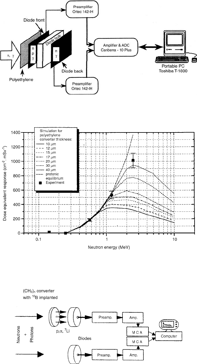
acquisition, as indicated in Figure 10.54. Data analysis is
performed using the Ortec Maestro II software.
Figure 10.55 shows the simulated dose-equivalent
response for normally incident neutrons as a function
of neutron energy for this dosimeter configuration and
several polyethylene converter thicknesses, together with
the experimental values obtained. The dosimeter response
may become flatter if the polyethylene converter thickness
is reduced, as deduced from the figure. Once this thick-
ness is selected, it is obvious from the results obtained
that it is necessary to reduce as much as possible the
energy cutoff introduced in order to increase the response
to 144, 250, and 570-keV neutrons.
Superheated emulsions and silicon diodes were stud-
ied by Vareille et al. [39] as radiation sensor for personal
and area monitors. The detectors were analyzed with
respect to their neutron sensitivity and their overall suit-
ability for practical dosimetry. The Classical Differential
FIGURE 10.53 (a) The experimental results of exposure of SDD-100 material to monoenergetic neutrons from RARAF (Nevis
Labs), Van de Graaff, and the US National
Institutes of Standards and Technology research reactor. The solid line is adapted from
information provided in the ICRP
Report 60. (b) Data points have been modified to include estimated albedo response and then
compared to fluence to individual dose-equivalent, penetrating, conversion factor, from which
n-capture gamma-ray contribution has
been subtracted. (From Reference [42]. With permission.)
cm
R
H
Ch-10.fm Page 461 Friday, November 10, 2000 12:04 PM
462 Radiation Dosimetry: Instrumentation and Methods
FIGURE 10.54 Schematic diagram of the experimental setup. (From Reference [43]. With permission.)
FIGURE 10.55 Experimental and calculated dose-equivalent response for normally incident neutrons as a function of neutron
energy. (From Reference [43]. With permission.)
FIGURE 10.56 Block diagram of the Classical Differential Method. (From Reference [39]. With permission.)
R
H
Ch-10.fm Page 462 Friday, November 10, 2000 12:04 PM
Neutron Dosimetry 463
Method (CDM) was studied, employing two identical p-
n junctions, one bare and one covered by a
10
B-loaded
polyethylene converter (typically 35
m thick). In the
CDM (Figure 10.56), the difference of the two diode
counts is taken, as it should theoretically be free of elec-
tronic background and
r contribution. Unfortunately, the
two diodes are never truly identical and, to avoid the
sensitivity, it was necessary to set a threshold at 600 keV,
despite the removal of most metal parts and the reduction
of the depleted layer to 10
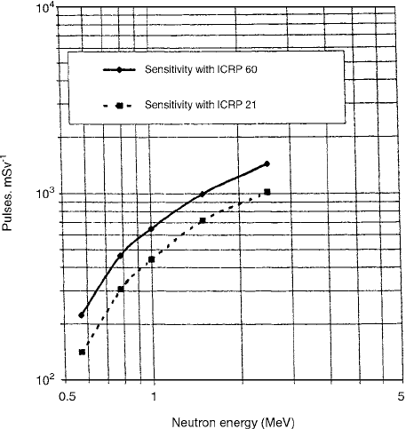
m. In the 1–4 MeV neutron
energy range, the sensitivity in terms of individual dose
equivalent falls between 0.5 and 1 pulse per
Sv (Figure
10.57). Thermal neutrons are also detected, due to the
10
B
converter.
A method using one PN junction covered with a
hydrogenous converter (
10
B-loaded) was proposed by
Bordy et al. [44] for individual neutron dosimetry. This
method is based on a pulse-shape analysis to discriminate
the photon signal from the neutron signal. It allows drastic
reduction of the photon sensitivity (by a factor of 1000).
By applying a neutron correction factor to the low-energy
events, the gap in neutron sensitivity for intermediate
energy can be partly filled. Lead shields used to surround
the detector allow the remaining photon sensitivity to be
decreased by a factor of two. An especially designed
hydrogenous moderator placed at the top of the detector
allows the neutron sensitivity to be increased by a factor
of two for 250-keV neutron energy.
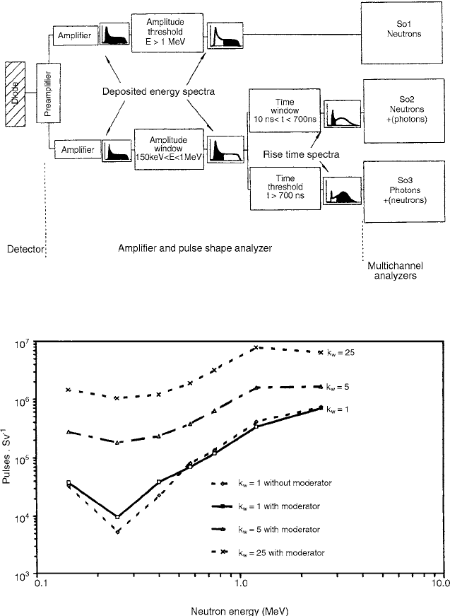
The device (Figure 10.58) consists of 3 parts: (1) the
detector and preamplifier (Intertechnique PSC 762); (2) the
amplifier step and the pulse shape analyzer, all made of
commercial NIM standard board; and (3) three multichan-
nel analyzers that record the spectra corresponding to Sol,
So2, and So3. The detector consists of (a) a Canberra PIPS
diode (300-
m thickness, bulk resistivity: 600 cm, sen-
sitive area: 1 cm
2
) covered with (b) a polyethylene con-
verter
10
B-loaded (5 10
15
bore, 30
m thick). Conduc-
tive rubber rings (c) and an aluminum plate (d) are
used to apply a reverse-bias voltage to the junction for
12 V. The depleted layer is about 30
m thick. Two printed
circuits (e) join the different pieces together.
The rise time measurements are carried out with a
time amplitude converter (TAC). The rise time is measured
between a “start” and a “stop” signal related to the event
being measured. The amplitude of the logic pulses gener-
ated by the TAC is related to the interval between these
two signals. The “start” signal is generated when the ana-
log input pulse crosses a low-level threshold. This marks
the arrival time of the event. The “stop” signal is produced
by a timing single channel analyzer when the peak of the
input pulses is detected; this technique uses the zero-
crossing of a bipolar pulse related to the input pulse. Thus,
the rise time is virtually independent of the input signal
amplitude.
A dip in neutron sensitivity is noticed around 250 keV
(Figure 10.59). An attempt has been made to obviate this
problem by applying a weighting factor and adding
hydrogenous moderator. The moderator allows the sensi-
tivity to be increased around 0.25 MeV (Figure 10.59),
but this sensitivity remains low.
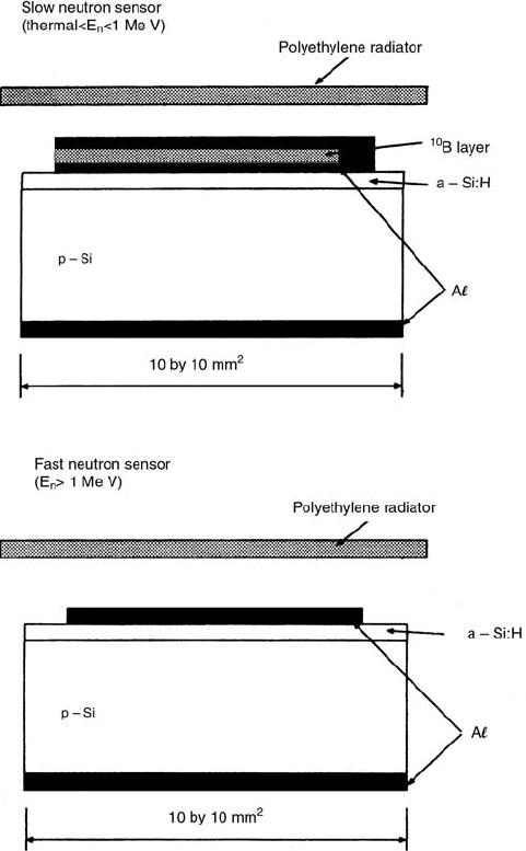
A real-time personal neutron dosimeter has been
developed by Nakamura et al. [45] The dosimeter contains
two neutron sensors, a fast neutron sensor and a slow
neutron sensor, which are both p-type silicon semiconduc-
tor detectors contacted with two different radiators of
polyethylene and boron. The neutron detection efficiencies
of these sensors were measured in a thermal neutron field
and monoenergetic neutron fields from 8 keV to 22 MeV.
Figure 10.60 shows the cross-sectional views of the
fast and slow neutron sensors. The fast neutron sensor is
a 10 10-mm
2
p-type silicon crystal, on which an amor-
phous silicon hydride is deposited. The slow neutron sen-
sor is also a 10 10-mm
2
p-type silicon on which a
natural boron layer is deposited around an aluminum elec-
trode to detect
and Li ions from the
10
B(n,
)
7
Li reaction.
Both sensors are in contact with 80-
m-thick, polyethyl-
ene radiators to produce recoil protons from the H(n, n)p
reaction. The slow neutron sensor has some sensitivity for
fast neutrons but is mainly used to measure neutrons with
energies less than 1 MeV, while the fast neutron sensor
measures neutrons with energies in the MeV region.
The detector is operated by applying the opposite bias
of
15 V, and a depletion layer of 60
m thickness is
generated under the amorphous silicon hydride, which can
fully absorb
,
7
Li, and recoil proton energies but absorbs
FIGURE 10.57 Fluence response of the CDM coupled diodes
as a function of neutron energy
(normalized to 1 cm
2
). (From
Reference [39]. With permission.)
k
w
Ch-10.fm Page 463 Friday, November 10, 2000 12:04 PM
464 Radiation Dosimetry: Instrumentation and Methods
only a part of the gamma-ray energy in order to discrim-
inate easily between neutron output pulse heights from
gamma-ray output pulse heights. By using such pulse
height discrimination, the contribution of the gamma-ray
dose to the neutron dose can be suppressed within 1%
under a 1 Sv h
1
gamma-ray mixed field.
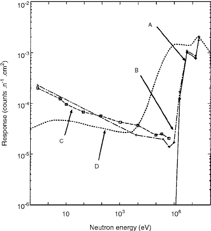
The energy response of the dosimeter to neutrons was
measured in a monoenergetic neutron field ranging from
8 keV to 15 MeV and in a 22-MeV quasimonoenergetic
neutron field. Detection efficiency was obtained by sum-
mation of all neutron pulses beyond the bias level and
division of the sum by the neutron fluence, and the results
were expressed as counts per n cm
2
. The bias level for
gamma-ray pulse cutoff was determined to be at a position
corresponding to the ambient gamma-ray dose equivalent
of 1 Sv h
1
in free air. The responses of fast and slow
neutron sensors to fluence as a function of neutron energy
are shown in Figure 10.61, together with the calculated
response using the MORSE-CG Monte Carlo code. An
ideal response of the neutron dosimeter must be close to
the fluence-to-dose equivalent conversion factor (drawn
as a dotted line in Figure 10.61) over a wide range of
neutron energy but, as seen in Figure 10.61, for neutron
energies from 100 keV to 1 MeV. However, practically
speaking, this underestimation can be compensated for by
the slight overestimation in the lower-energy region (espe-
cially in the thermal energy region), considering that the
actual neutron field has a continuous neutron spectrum,
FIGURE 10.58 Block diagram of the experimental setup. (From Reference [44]. With permission.)
FIGURE 10.59 Dose-equivalent response obtained with and without moderator and by using the weighting factor . (From
Reference [44]. With permission.)
k
w
Ch-10.fm Page 464 Friday, November 10, 2000 12:04 PM
Neutron Dosimetry 465
usually containing an amount of thermal neutron compo-
nents.
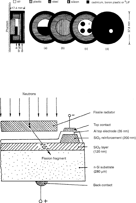
A combined active/passive personal neutron dosime-
ter was proposed by Luszik-Bhadra et al. [46] It consists
of a position-sensitive silicon diode which is covered on
four different positions by different thermal and fast neu-
tron absorbers, moderators, and converters—including a
passive CR-39 detector.
A sketch of the dosimeter configuration under test is
shown in Figure 10.62. For a first feasibility study, it is
assumed that a single position-sensitive silicon diode can
be used. In front of the silicon diode (315
m thick, 3-cm
2
sensitive area), a batch of thermal and fast neutron con-
verters was placed at 1 mm distance. The thermal neutron
converters (section (c) in Figure 10.62) consist of three
LiF layers behind different shieldings. The positions are
denoted by “Albedo”, “Closed” and “Front.” The fast neu-
trons are detected separately in position 4. Fast neutron
converters and moderators are different sheets of hydrogen-
containing plastics. They consist of a polyethylene sheet
0.5 mm thick (with the evaporated LiF layers), followed
by two CR-39 sheets, each 0.7 mm thick. The one is used
as a passive CR-39 detector and the other one serves as a
CR-39 designed converter.
The registration of heavy charged panicles by means
of MOS breakdown counters was suggested by Tomma-
sino et al.[47] A neutron sensor consists of a MOS thin-
film capacitor in combination with a fissile radiator
(Figure 10.63). The operation voltage applied to the MOS
element must be chosen such that spontaneous break-
downs through the silicon dioxide layer can be neglected.
Incident neutrons generate fission fragments within the
radiator which enter the silicon dioxide. Along their paths
secondary charge carriers are produced in high concentra-
tion, which gives rise to a local degradation of the break-
down field strength. The result is electric breakdowns at
the sites of the fission fragment tracks which can be
counted as voltage pulses by using a simple electronic
FIGURE 10.60 Cross-sectional view of the slow and fast neutron sensors. (From Reference [45]. With permission.)
Ch-10.fm Page 465 Friday, November 10, 2000 12:04 PM
466 Radiation Dosimetry: Instrumentation and Methods
circuit. The pulse rate z is proportional to the momentary
neutron flux density in time-dependent neutron fields or
to the corresponding derived dosimetric quantities. In the
course of each breakdown, a hole is created in the silicon
dioxide and in the aluminum top electrode by vaporizing
material. The total number of vaporization spots on the
sensor surface is an additional measure of the fluence of
incident neutrons—similar to the number of etched tracks
in solid-state nuclear track detectors. (Dorschel et al. [48])
VII. BONNER SPHERE AND OTHER
PORTABLE NEUTRON MONITORS
Bonner sphere consists of a central detector, sensitive to ther-
mal neutrons, and a moderator sphere. A
3
He proportional
counter is often used as the central detector. A knowledge
of the Bonner sphere response as a function of incident
neutron energy is required to interpret Bonner sphere mea-
surements. The response of a Bonner sphere is defined as
the ratio of yield over neutron fluence.
A Bonner sphere spectrometer (BSS) is the only neu-
tron monitor which allows the spectral neutron fluence to
be measured in a wide energy range, from thermal up to
about 20 MeV. The ambient dose-equivalent value can be
calculated from the spectrum by applying the correspond-
ing fluence to dose-equivalent conversion function. The
responses of the spheres are functions of the neutron energy
and moderator diameter. The larger the sphere diameter,
the higher the neutron energy where the response reaches
its maximum.
To achieve an isotropic response, a portable monitor
for measuring H
*
(10) should ideally consist of spherical
detecting elements; an orthospherical detector surrounded
by a spherical or an orthospherical converter is convenient
from a practical point of view. This is generally the case
for rem counters where the detecting element is a propor-
tional or GM counter and the converter is a polyethylene
sphere.
To yield an isodirectional response with respect to ,
an individual dosimeter for measuring should have
a flat converter and a flat active detector volume. This is
usually the case, for example, for dosimeters based on the
use of a nuclear emulsion, a solid-state detector (e.g., CR-
39 foils), or a silicon diode covered with hydrogenous
converters, the thickness of which, however, often varies
considerably from
d 10 mm, and none of the above
dosemeters is really isodirectional. This can also be seen
in Figure 10.64, where the ideal angular response of an
individual dosimeter with respect to fluence for various
neutron energies is compared with experimental results
for CR-39 dosimeters. [49]
The response functions of four widely used Bonner
sphere spectrometers (BSS) with an LiI scintillator and
different
3
He detectors were calculated by Kralik et al.
[50] by means of the three-dimensional Monte Carlo neu-
tron transport code, MCNP, taking into consideration a
detailed description of the detector setup; they were then
compared with experimental calibration data. In order to
obtain agreement between the calculated response func-
tions and the measured calibration data, different scaling
factors had to be applied to the response functions calcu-
lated for the various sphere diameters, and even the shape
had to be adjusted in order to fit the thermal neutron
response measured (see Figure 10.65). Better results were
obtained by means of the three-dimensional neutron
transport Monte Carlo code, MCNP, although details of
the detector setup were still neglected.
Response functions of Bonner sphere spectrometers
were calculated by Sannikov et al. [51] for neutron ener-
gies from 10 MeV to 1.5 GeV by the Monte Carlo high-
energy transport code, HADRON. Calculations were
made for two types of thermal neutron detectors inside
the Bonner spheres:
3
He proportional counter and
6
LiI
scintillation detector. The results obtained are compared
with calculations using the MCNP and the LAHET Monte
Carlo codes.
The MCNP code was extended up to 100 MeV using
the neutron cross sections for hydrogen and carbon from the
FIGURE 10.61 Dosimeter response to fluence as a function of
neutron energy with the ambient dose-equivalent conversion factor
described in ICRP 74. Key to lines: A (— — — — ) fast neutron
sensor, B (
.
–
.
–
.
) slow neutron sensor, C (----) calculated response,
D (
....
)
ambient dose-equivalent conversion factor. (From Refer-
ence [45]. With permission.)
H
p
H
p
d()
Ch-10.fm Page 466 Friday, November 10, 2000 12:04 PM
Neutron Dosimetry 467
LA 100 library. The high-energy transport code HADRON
is based on the cascade-exciton model of nuclear reac-
tions. This model includes a cascade stage (modified ver-
sion of the Dubna cascade model), a pre-equilibrium stage
(exciton model), and an equilibrium evaporation stage.
Low-energy neutrons are transported by the Monte Carlo
code FANEUT. The results for low neutron energy
responses of the
3
He BSS were found to be in a good
agreement with the MCNP data.
The LAHET code, developed at Los Alamos National
Laboratory, is based on the HETC high-energy transport
code of ORNL. This program has different options for
simulation of inelastic interactions of hadrons with nuclei:
Bertini and the ISABEL cascade models. At the de-exci-
tation stage of nuclear reaction, two versions of the pre-
equilibrium exciton model or the Fermi breakup model
may be used. The transport of the low-energy neutrons is
calculated by the code HMCNP, which is a modified ver-
sion of MCNP.
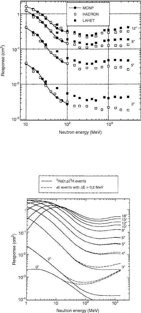
The results of calculations performed by the three
Monte Carlo codes are shown in Figure 10.66 for several
Bonner spheres. The data obtained by the MCNP and
HADRON programs agree within the limits of 15% below
100 MeV. This is not the case for the LAHET data, which
are much higher as a rule.
The more pronounced differences for small spheres in
Figure 10.66 may be explained by the large contribution
of low-energy neutrons from the first interaction of
FIGURE 10.62 Sketch of the dosimeter setup (a) the albedo window, (b) the silicon diode, (c) the front side of the plastic
converter with three LiF layers, and (d) the cadmium sheet with front window. The four positions on section (c) are,
counterclockwise, (1) “Albedo,” (2) “Closed,” (3) “Front,” and (4) “Fast” without
6
Li converter. (From Reference [46]. With
permission.)
FIGURE 10.63 Scheme and operation principle of a MOS breakdown sensor. (From Reference [48]. With permission.)
Ch-10.fm Page 467 Friday, November 10, 2000 12:04 PM

468 Radiation Dosimetry: Instrumentation and Methods
neutrons with carbon nuclei. In the case of large spheres,
this effect is masked by averaging the processes of neutron
production and absorption over several collisions.
The full set of the
3
He BSS smoothed-response func-
tions is shown in Figure 10.67 by solid curves from 1 MeV
to 1500 MeV (MCNP below 10 MeV and HADRON
above 10 MeV). These responses include only
3
He(n,p)
3
H
events with energy depositions from 0.2 to 0.9 MeV. The
dashed curves in Figure 10.67 show the total responses,
including all events above 0.2 MeV.
Measurements of Bonner sphere response functions
in reactor-filtered neutron beams were intercompared by
Siebert et al. [52] with calculations, and the influence of
the moderator’s mass density is studied in calculations.
The
3
He content of the proportional counter used as the
central detector has been experimentally determined and
roughly confirmed by calculations.
The central detector is a spherical
3
He proportional
counter, Centronic Type SP 90, 3.2 cm in inner diameter
and with a stainless steel wall 0.5 mm thick. The moderator
spheres are made of polyethylene (CH
2
)
n
and are 7.62 cm,
11.43 cm, 15.24 cm, and 20.32 cm in diameter with a
mass density,
, of 0.95 0.005 g cm
3
. The fittings
around the detector also consist of (CH
2
)
n
, their mass
FIGURE 10.64 Angular dependence of the response of individual dosimeters with respect to fluence for various neutron energies.
Ideal theoretical curves (approximated by
H(10)/ and experimental results with CR-39 neutron dosimeters. Key: () 14 to 16 MeV,
(
) 3 to 5 MeV, () 1.3 to 1.6 MeV, (*) 0.45 to 1.1 MeV, () 0.13 to 0.4 MeV. (From Reference [59]. With permission.
FIGURE 10.65 Comparison of calculated response functions of the PTB-C BSS for the 3, 5. and 10 spheres with
corresponding experimental data. (From Reference [50]. With permission.
RE
n
()
Ch-10.fm Page 468 Friday, November 10, 2000 12:04 PM
Neutron Dosimetry 469
density being 0.944 0.003 g cm
3
. Reactor filtered
beams with nominal energies 24 keV and 144 keV serve
as the neutron source.
Figure 10.68 shows smoothed Bonner sphere (BS)
responses as calculated for four sets of parameters as a
function of moderator diameter. The moderator mass den-
sity is 0.95 g cm
3
. The response increases with higher
pressure. The peak position for the higher energy is shifted
to larger diameters.
P
He
200 kPa, E
n
144 keV ------
P
He
172 kPa, E
n
144 keV — . —
P
He
200 kPa, E
n
24 keV - - -
P
He
172 kPa, E
n
24 keV ——
A neutron counter which is applicable to spectrometry
and dosimetry over a wide energy range has been devel-
oped by Toyokawa et al. [53] It gives energy spectra,
integral fluences, and dose equivalent of incident neutrons
with energies from thermal to 15 MeV. The counter con-
sists of a spherical polyethylene moderator and three slen-
der
3
He position-sensitive proportional counters inserted
into the moderator. The position-sensitive proportional
counters give detection position profiles of neutrons
slowed down to thermal energies in the spherical moder-
ator, which gives the above-mentioned information.
A schematic drawing of the counter and the setup used
for response calculations is shown in Figure 10.69. The
diameter of the spherical moderator is 26 cm. It was esti-
mated using Monte Carlo simulations so that the responses
extend up to 15 MeV. The outer diameter and counter are
1 cm and 0.9 cm, respectively. The counting gas is a
mixture of
3
He (101 kPa) and CF
4
(70 kPa). Because the
addition of the CF
4
gas shortens the ranges of the proton
and the triton produced in the
3
He(np)
3
H reaction, the
proportional counter has a good position resolution, eval-
uated to be about 0.7 cm in FWHM when the applied
voltage is 1500 V. The position of the neutron detection
was calculated by the charge division method.
Figure 10.70 shows the calculated position profiles (or
the counter responses as a function of the axial position)
for various monoenergetic neutrons. In each calculation,
10
7
neutrons, which corresponds to the neutron fluence of
1.9 10
4
cm
2
at the center of the moderator (when the
moderator is removed), were incident of the counter.
The abscissa of Figure 10.70 shows the axial position
in the position-sensitive proportional counter placed along
the x-axis (Figure 10.69). Therefore, the neutrons are inci-
dent on the counter from the right-hand direction in Figure
10.70. As the energy of the incident neutrons increases, the
position profiles spread to the deep region, which is within
about 5 cm of the axial position. The position profiles
show the approximate distribution of the thermalized neu-
trons. It is shown in Figure 10.70 that the distribution is
sensitive to the energy of the incident neutrons. In the first
step of the feasibility study of the counter, thought of as a
neutron spectrometer to be used under various geometric
conditions of neutron irradiation, only the responses
obtained for the x-proportional counter for the point-source
FIGURE 10.66 Comparison of the
3
He BSS responses calcu-
lated by the Monte Carlo codes MCNP, HADRON, and LAHET.
(From Rference [51]. With permission.)
FIGURE 10.67 Response functions of the
3
He BSS with
(dashed curves) and without (solid curves) contribution of sec-
ondary charged particles from high-energy hadrons calculated
by the codes MCNP (below 10 MeV) and HADRON (above 10
MeV). (From Reference [51]. With permission.)
Ch-10.fm Page 469 Friday, November 10, 2000 12:04 PM