Satas D., Tracton A.A. (ed.). Coatings Technology Handbook
Подождите немного. Документ загружается.

This Page Intentionally Left Blank
27
Sputtered Thin
Film
Coatings
Brian
E.
Aufderheide
W.
H.
Rrtrdy
Conlpony,
Milwnukrr.
Wisconsin
1
.O
HISTORY
Sputtering was discovered in 1852 when Grove observed metal deposits at the cathodes
of
a cold cathode glow discharge. Until 1908 it was generally believed that the deposits
resulted from evaporation at hot spots on the cathodes. However, between 1908 and 1960,
experiments with obliquely incident ions and sputtering of single crystals by ion beams
tended
to
support
a
momentum transfer mechanism rather than evaporation. Sputtering
was used to coat mirrors
as
early as 1877, finding other applications such
as
coating fabrics
and phonograph wax masters in the 1920s and
30s.
The subsequent important process
improvements of radio frequency (rf) sputtering, allowing the direct deposition of insula-
tors, and magnetron sputtering, which enables much higher deposition rates with less
substrate damage, have evolved more recently. These two developments have allowed
sputtering to compete effectively with other physical vapor deposition processes such as
electron beam and thermal evaporation for the deposition of high quality metal, alloy, and
simple inorganic compound coatings, and
to
establish its position
as
one of the more
important thin film deposition techniques.
2.0
GENERAL PRINCIPLES
OF
SPUTTERING
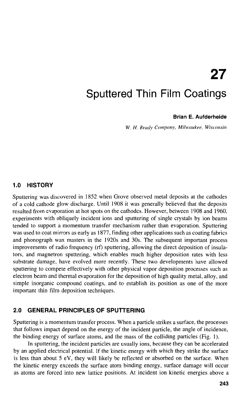
Sputtering is
a
momentum transfer process. When a particle strikes
a
surface, the processes
that follows impact depend on the energy
of
the incident particle, the angle of incidence,
the binding energy of surface atoms, and the mass of the colliding particles (Fig. 1).
In sputtering, the incident particles are usually ions, because they can be accelerated
by an applied electrical potential. If the kinetic energy with which they strike the surface
is less than about 5 eV, they will likely be reflected or absorbed on the surface. When
the kinetic energy exceeds the surface atom binding energy, surface damage will occur
as atoms are forced into new lattice positions. At incident ion kinetic energies above a
243
244
AUFDERHEIDE
Incident
Ion
\
Reflected Ion
or Neutral
n
Secondary
Electrnn
~
Sputtered Atom
Figure
1
Schematic representation
of
some
of
the
processcs that
follow
ion impact during sputter-
ing. (Courtcsy
of
W.
H.
Brady Co.)
threshold, typically
10-30
eV, atoms may be dislodged
or
sputtered from the surface. At
normal incidence, multiple internal collisions are required, but at lower angles, sputtered
atoms can be produced directly. These sputtered atoms and ions can be condensed on a
substrate to form a thin film coating.
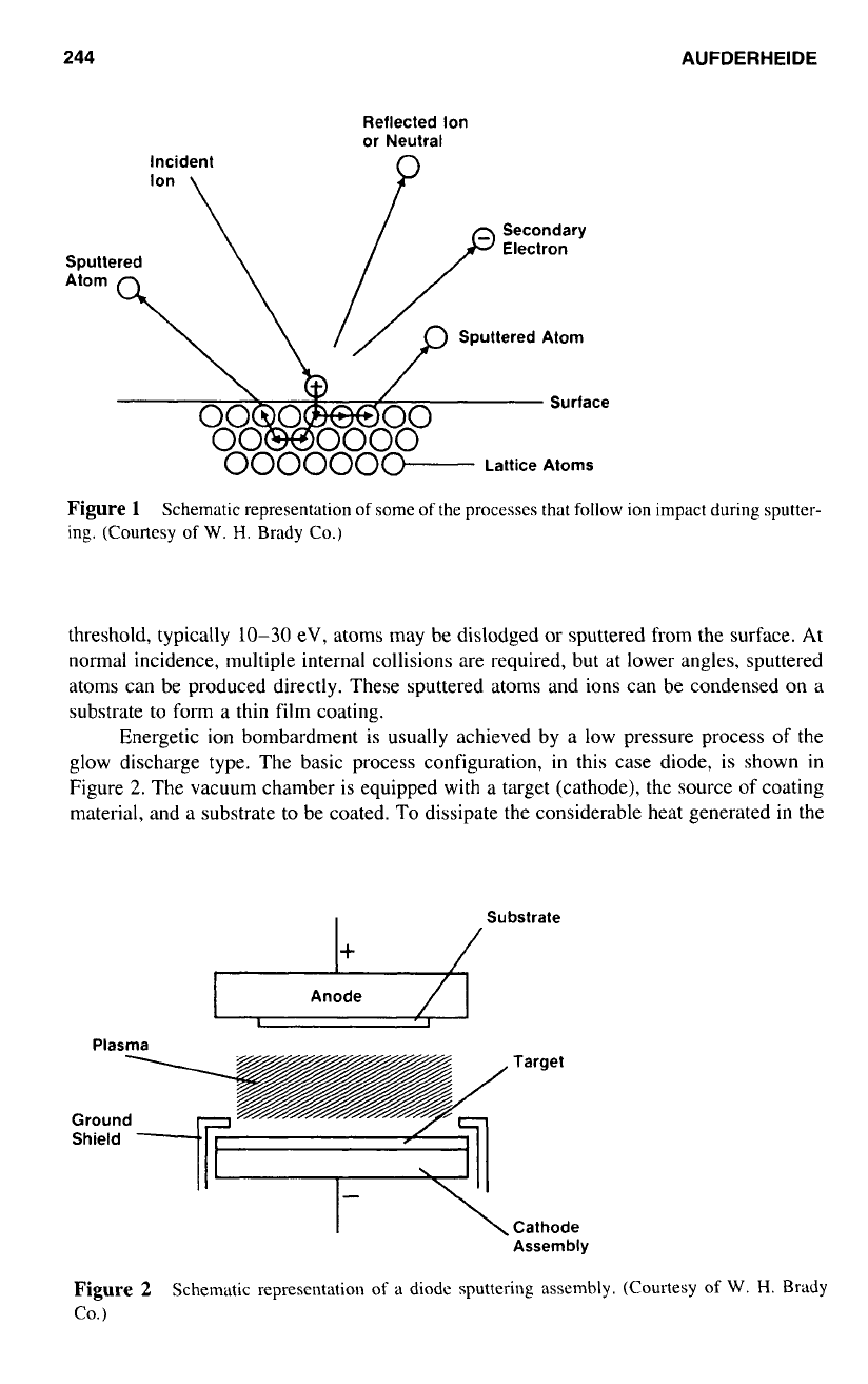
Energetic ion bombardment is usually achieved by a low pressure process of the
glow discharge type. The basic process configuration, in this case diode, is shown
in
Figure
2.
The vacuum chamber is equipped with a target (cathode), the source of coating
material, and a substrate to be coated. To dissipate the considerable heat generated
in
the
I+
/
Substrate
Anode
Plasma
Target
Ground
Shield
Cathode
Assembly
Figure 2
Schematic represcntation
of
a
diode sputtering assembly. (Courtesy
of
W.
H.
BEidy
Co.)
SPUTTERED
THIN
FILM
COATINGS
245
ARGON
“t
E
2.0
1.0
0.5
0
Ti
3
100 200
300
_cL-.”ci
c
400
500
600
700
800
ION ENERGY
(eV)
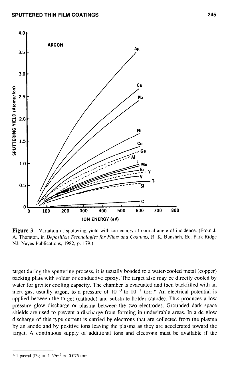
Figure
3
Variation
of
sputtering yield
with
ion energy
at
normal angle
of
incidence.
(From
J.
A.
Thomton,
in
Deposition
Techolo,qies
,for
Films
cm/
Coutiqs,
R.
K.
Bunshah, Ed. Park Ridge
NJ:
Noyes Puhlications,
1982,
p.
179.)
target during the sputtering process, it is usually bonded
to
a
water-cooled metal (copper)
backing plate with solder or conductive epoxy. The target also may be directly cooled by
water for greater cooling capacity. The chamber is evacuated and then backfilled with an
inert gas, usually argon. to
a
pressure of to
10”
torr.* An electrical potential is
applied between the target (cathode) and substrate holder (anode). This produces a low
pressure glow discharge or plasma between the two electrodes. Grounded dark space
shields are used to prevent a discharge from forming in undesirable areas.
In
a
dc glow
discharge
of
this type current is carried by electrons that are collected from the plasma
by an anode and by positive ions leaving the plasma
as
they are accelerated toward the
target.
A
continuous supply of additional ions and electrons must be available if the
246
AUFDERHEIDE
discharge is to be sustained. Some of the ions striking the target surface generate secondary
electrons, which are accelerated by the cathode potential. These electrons, with energies
approaching the applied potential, enter the plasma and ionize gas atoms, producing the
necessary additional ions and electrons to sustain the discharge.
The relative rates of deposition for different materials depend largely
on
the sputter
yield (Fig.
3),
defined as the number
of
target atoms ejected per incident particle. Sputter
yield depends on the target material, silver showing the highest yield, and generally increas-
ing with incident ion energy and mass.
3.0
SPUlTER DEPOSITION SOURCES
3.1
Direct Current Diode Sputtering
The simplest and oldest sputter deposition source is dc diode. The two electrodes are
usually parallel to each other, spaced
4-8
cm apart and the substrate is placed
on
the
anode as in Figure 2. The applied potential is typically 1000-3000
V
dc with argon
pressures of about 0.075-0.12 torr. The dc diode configuration has important disadvan-
tages, including low deposition rate
(-400
8hin for metals), high working gas pressure,
targets limited to electrical conductors, and bombardment of the substrate by plasma elec-
trons, resulting in substrate heating. The cathode systems discussed next can be used to
improve
on
the performance of the dc diode.
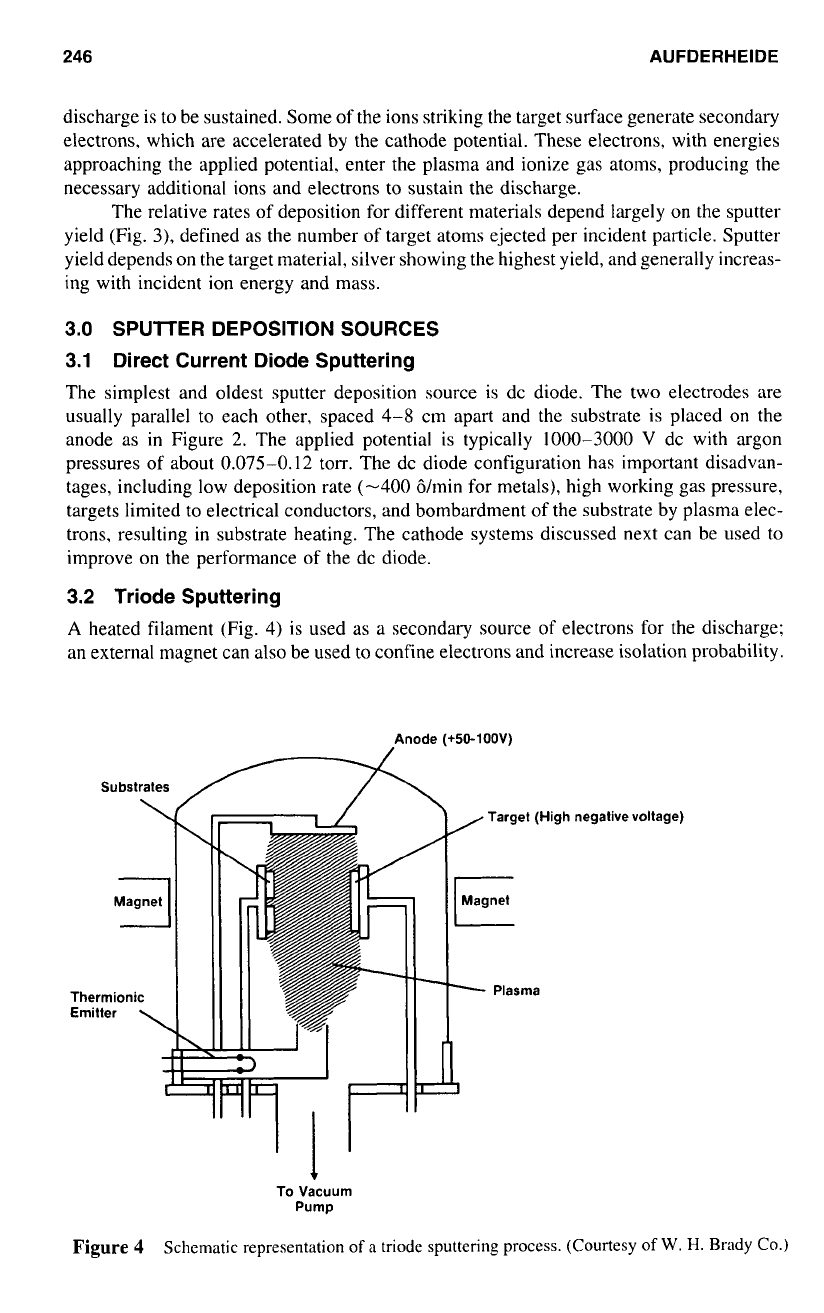
3.2
Triode Sputtering
A
heated filament (Fig.
4)
is used as a secondary source of electrons for the discharge;
an external magnet can also be used to confine electrons and increase isolation probability.
Anode (+50-100V)
Target (High negative voltage)
CI
Magnet
-
Plasma
To
Vacuum
Pump
Figure
4
Schematic representation
of
a
triode sputtering process. (Courtesy
of
W.
H.
Brady Co.)
SPUTTERED
THIN
FILM COATINGS
247
Triodes can produce much higher deposition rates, up
to
several thousand angstroms per
minute, at lower pressures,
(0.5-1
X
IO-?
torr) and voltages
(50-100
V).
The usefulness
of
triodes has been limited by difficulties in scaling up to large cathode sizes and corrosion
of
the emitter filament by chamber gases.
3.3 Radio
Frequency Sputtering
Nonconducting materials cannot be directly sputtered with an applied dc voltage because
of positive charge accumulation
on
the target surface. If an
BC
potential of sufficiently
high frequency is applied, an effective negative bias voltage is produced such that the
number of electrons that arrive at the target while
it
is positive equals the number of ions
that arrive while it is negative. Because the mass of the electron is very small relative to
ions present, the target is positive for only a very short time, and deposition rates for rf
diode are almost equivalent to dc diode. This resulting negative bias allows sputtering of
an
insulating target. The frequency used
in
most practical applications is usually
13.56
MHz, a radio frequency band allocated for industrial purposes by the Federal Communica-
tions Commission. Rf sputtering allows insulators as well as conductors and semiconduc-
tors
to
be deposited with the same equipment and also permits sputtering at a lower
pressure
(S-l5
X
IO”
torr). One major disadvantage
of
rf sputtering is the need for
electromagnetic shielding to block the rf radiation. Also, the power supplies, matching
network, and other components necessary to achieve a resonant rf network are very com-
plex.
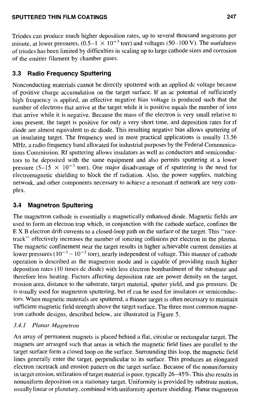
3.4 Magnetron Sputtering
The magnetron cathode is essentially
a
magnetically enhanced diode. Magnetic fields are
used to form an electron trap which, in conjunction with the cathode surface, confines the
E
X
B
electron drift currents
to
a closed-loop path on the surface of the target. This “race-
track” effectively increases the number
of
ionizing collisions per electron in the plasma.
The magnetic confinement near the target results in higher achievable current densities at
lower pressures
(
lop3
-
10”
torr), nearly independent of voltage. This manner of cathode
operation is described as the magnetron mode and is capable of providing much higher
deposition rates
(IO
times dc diode) with less electron bombardment of the substrate and
therefore less heating. Factors affecting deposition rate are power density on the target,
erosion area, distance
to
the substrate, target material, sputter yield, and gas pressure. DC
is usually used for magnetron sputtering, but rf can be used for insulators or semiconduc-
tors. When magnetic materials are sputtered, a thinner target is often necessary
to
maintain
sufficient magnetic field strength above the target surface. The three most common magne-
tron cathode designs. described below. are illustrated in Figure
5.
3.4.
l
PImar
Magnetron
An array of permanent magnets is placed behind a flat, circular or rectangular target. The
magnets are arranged such that areas in which the magnetic field lines are parallel to the
target surface form a closed loop on the surface. Surrounding this loop, the magnetic field
lines generally enter the target, perpendicular to its surface. This produces an elongated
electron racetrack and erosion pattern on the target surface. Because of the nonuniformity
in target erosion. utilization of target material is poor, typically
26-458.
This also results in
nonuniform deposition on a stationary target. Uniformity is provided by substrate motion,
usually linear or planetary. combined with uniformity aperture shielding. Planar magnetron
248
AUFDERHEIDE
ANODE
/
CATHODE
Figure
5
Clockwise from
uppcr
left: schematic reprcsentations
of
planar magnetron. gun-type
magnetron,
and
cylindrical post magnetron sputtering
sources.
(Adaptcd
from
J.
A.
Thornton,
in
Depositiorl
Trc.hrrologir.sfor
Filrr7s
~r7d
Corctirlgs,
R.
F.
Bunshah. Ed. Park Ridge
NJ:
Noyes Publica-
tions. 1982,
pp.
194-195.)
cathodes are usually operated at 300-700
V
providing a current density of 4-60 mA/cm'
or a power density of 1-36 W/cm'.
Deposition rates are generally proportional
to
the power delivered
to
the target.
Much
of
this power is dissipated as target heating. The primary factor limiting magnetron
deposition rates is the amount
of
power that can be applied to the target without causing
it
to
melt, crack, or warp. This is controlled by the cathode water cooling design. and the
thermal conductivity of the target, the backing plate. and the interface between them. The
planar magnetron cathode has been scaled up in production applications to several meters
in length and serves as an important industrial coating tool.
3.4.2
C~dindrical
Magnetron
Two variations on a cylindrical cathode design can be used to coat large surface areas:
the cylindrical post magnetron, which sputters outward from a central post target. and the
cylindrical hollow or inverted magnetron. which has target erosion
on
the inner wall
of
a cylindrical target. Operating parameters are similar to the planar magnetron. The
E
X
SPUTTERED
THIN
FILM
COATINGS
249
B
(electric field strength
X
magnetic flux density) current closes on itself by going around
the post or cylinder. Electrostatic or magnetic containment is often used to minimize end
losses. Erosion is uniform along the post or inside
of
the cylinder. This enables fairly
uniform coating without substrate movement. Hollow cathodes are especially effective at
coating objects of complex shapes. Another cylindrical cathode, the rotatable magnetron,
uses
a
magnet array similar to
a
planar magnetron and rotates the target or magnets to
obtain uniform erosion.
3.4.3
Ritlg
or
Gut1
Magnetrot1
The ring or gun magnetron source includes
a
circular cathode and
a
concentric centrally
located anode. As with other magnetrons. high deposition rates are possible with little
substrate heating. Because of the circular design, planetary substrate motion is necessary
for deposition uniformity. This design is extensively used for small-scale applications but
has not been scaled up to larger dimensions. Arrays of these cathodes have been used to
coat large areas.
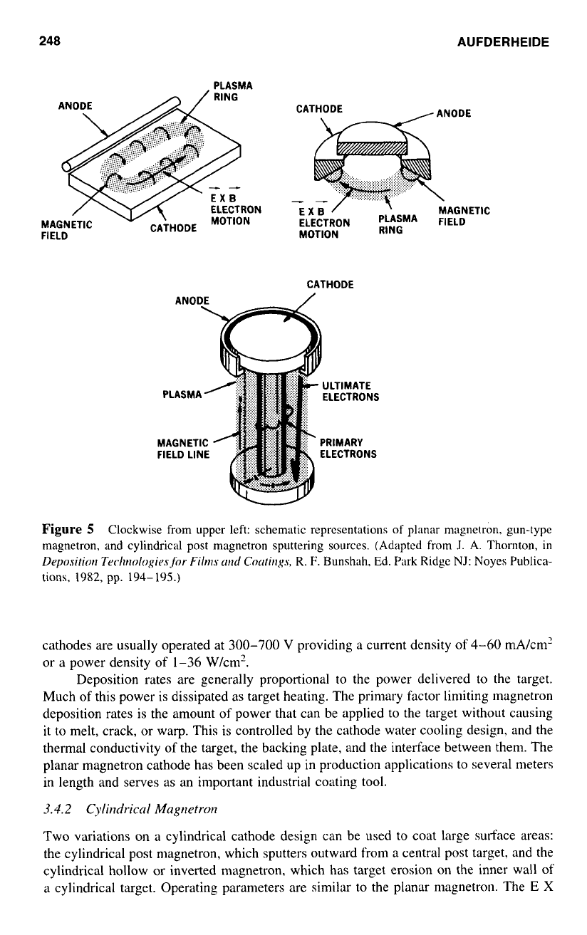
3.5
Beam Sputtering
A separate ion beam source (Fig.
6),
as
opposed
to
a
glow discharge, may be used to
erode the surface of
a
target. The energy, direction, and current density
of
the ion beam
may be controlled independently, and it is possible to work at background pressures lower
than other sputter deposition methods used. Unique film properties can sometimes be
obtained using ion beam deposition, bit it is generally limited to coverage of rather small
areas and lower deposition rates.
3.6
Reactive Sputtering
Argon is usually employed
as
the working gas
in
sputter deposition processes. It is rela-
tively inert, being incorporated in the growing film only when trapped or embedded
in
TARGET
Figure
6
Schematic representation
of
ion bcnm sputtering source showing relative locations
of
target and substrate. (From
J.
A.
Thornton, in
Dq~osifior~
Tuchr~o/o~ir.s,for.
Fihs
urd
Cotrfirlsys.
R.
K.
Bunshah,
Ed.
Park Ridge,
NJ:
Noyes
Publications.
1982,
p.
21
1.)
250 AUFDERHEIDE
its surface. Other more reactive gases such as water vapor, oxygen, and nitrogen are
normally present in the deposition chamber as low level contaminants, which have been
outgassed from the substrate, target, and chamber walls. These gases may be incorporated
into the growing film by reacting with condensed atoms on the substrate surface, forming
small amounts of oxides, nitrites. carbides, and other similar compounds
of
the sputtered
material.
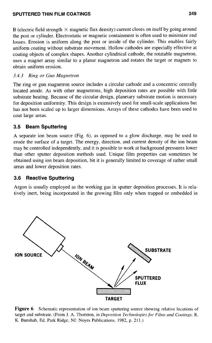
In reactive sputtering, gases are intentionally introduced into the deposition chamber
to completely react with the forming thin film. A gas manifold system (Fig.
7)
is often
used to provide uniform distribution of the reactive gas at the substrate and minimize
reactive gas at the target surface.
Reactive sputtering is a very nonlinear process. The growing film
on
the substrate
acts like
a
getter pump for the reactive gas up to the pressure at which a stoichiometric
compound is formed. At this point, the pumping rate of the substrate decreases substan-
tially, and reactive gas pressure increases in the chamber. This gas may react with the
surface of the target, resulting in decreased deposition rates due to lower sputter yields
of
compounds and other factors. Consequently, most reactive deposition processes attempt
to work near the transition region of the target, where stoichiometric compounds are
formed at the substrate and the cathode target is metallic. Reactive sputtering therefore
permits the formation of compounds from simple metallic targets in the dc mode or rf
Substrate
Plasma
Gas Manifold
Getter Surface
To
Vacuum
Planar
Pump
Magnetron
Cathode
Figure
7
Schematic representation
of
a reactive sputtering apparatus. (Courtesy
of
W.
H.
Brady
Co.)
SPUTTERED
THIN
FILM
COATINGS 251
mode. This process is widely used for deposition of oxides and nitrites such as silicon
oxides, silicon nitrite, titanium nitride, and indium tin oxide.
4.0
OTHER PROCESS CONSIDERATIONS
Vacuum chambers used for sputtering have to be capable of producing a vacuum better
than
5
X
lop4
torr to minimize contamination from background gases. A load lock is
used on some devices when contamination of the sputter chamber by gas absorbed when
the chamber is opened is unacceptable, or
to
decrease pump down time. A wide variety
of
pumping systems are used including diffusion, turbomolecular, and cryogenic pumps.
Throttling of the pumps is necessary in many cases due to high working pressures.
Most target materials have considerable surface contamination accumulated during
manufacture and storage. Targets are presputtered to a depth sufficient
to
remove these
contaminants before deposition. A shutter is often used to protect the substrate from the
contamination while the target is being cleaned.
The sputtering process can be very dependent on such equipment design factors as
gas distribution systems, position of pumps, and distance from target to substrate. These
factors and others must be carefully considered when transferring a process from one
chamber to another or when scaling up to production levels.
A
major factor controlling equipment configuration is the nature of the substrate.
The substrate may be small rigid pieces such as microelectronic circuitry or much larger
rigid items such as architectural glass. If the substrate is flexible, roll-to-roll processing
is often used. Equipment is designed to handle the substrate
in
a manner that will promote
the achievement
of
coating uniformity.
5.0
PROPERTIES
OF
SPUTTERED THIN
FILM
COATINGS
The electrical, optical, and other properties
of
thin films often vary from the properties
measured in bulk materials. Conditions present at the substrate during deposition can have
a significant influence on these properties. When a sputtered atom condenses on a substrate,
it transforms its kinetic energy to the surface lattice. The resulting loosely bonded atom
has mobility on the surface and will migrate over the surface, interacting with other ab-
sorbed atoms until it finds a permanent low energy site, or is desorbed.
As
the film thickness
builds, atoms within the lattice move to more stable positions by bulk diffusion.
For many metals, the mobility of surface and bulk atoms is related to the ratio
of
substrate temperature
(T)
and the melting point of the metal
(TI,,).
At low
TIT,,,
values,
surface and bulk diffusion play little role because atoms have insufficient energy to move
from their initial position. In films deposited under these conditions (Fig.
g),
the internal
crystal structure is poorly defined and has many defects; voids are also present due to
shading effects. Conditions tending
to
produce lower
TIT,,,
are higher melting temperature
target materials (e.g. refractory metals), substrate cooling, higher working gas pressures
(which “thermalize” or reduce sputtered atom energies), and reactive gases adsorbed on
the surface. Higher
TIT,,,
values result in more surface and bulk diffusion in the growing
film, producing denser columnar grains with fewer defects and defined boundaries.
In addition
to
substrate heating,
T
can effectively be raised by bombarding the
substrate with ions or electrons during deposition. In a diode system, the substrate is often
in the plasma, resulting in film heating due to high energy electron impact. A bias voltage
can also be applied
to
the substrate to accelerate incoming ions, increasing the kinetic