Roy K.K. Potential theory in applied geophysics
Подождите немного. Документ загружается.


15.2 Finite Difference Formulation/Direct Current Domain 479
Therefore, for the point i, j + h
E
2
,wecanwrite
dφ
dx
i,j+
hE
2
=
φ
i,j+
hE
2
− φ
i,j−
hE
2
(h
E
+ h
w
) /2
. (15.10)
Hence
σ
∂φ
∂x
i,j+hE/2
=
σ
i,j+hE/2
.h
−1
E
(φ
i,j+hE
− φ
i,j
) . (15.11)
Now
∂
∂x
σ
∂φ
∂x
will be from (15.9)
∂
∂x
σ
∂φ
∂x
i,j
=
2
h
E
+ h
w
)
σ
∂φ
∂x
i,j+hE/2
−
σ
∂φ
∂x
i,j−hW/2
*
. (15.12)
Putting the values from (15.10), we get
∂
∂x
σ
∂φ
∂x
i,j
=
2
h
E
+ h
w
σ
i,j+hE/2
h
E
φ
i,j+hE
− φ
i,j
−
σ
i,j−hw/2
hw
φ
i,j
− φ
i,j−hw
.
(15.13)
Hence (15.6) can be written as
∂
∂x
σ
∂φ
∂x
i,j
+
∂
∂z
σ
∂φ
∂z
i,j
+ q (x, z)=0
⇒
2
h
E
+ h
w
σ
i,j+hE/2
h
E
(φ
i,j+hE
− φ
i,j
) −
σ
i,j−hw/2
hw
(φ
i,j
− φ
i,j−hw
)
+
2
h
N
+ h
S
σ
i,j+hS/2
h
S
(φ
i,j+hS
− φ
i,j
) −
σ
i,j−hN/2
h
N
φ
i,j
− φ
i,j−hN/2,j
+ q
ii,j
=0. (15.14)
We can rewrite this equation separating the terms of ϕ as,
α
E
φ
i,j+hE
+ α
w
φ
i,j−hW
+ α
N
φ
i−hN,j
+ α
S
φ
i+hS,j
−α
P
φ
ij
+ q
ij
= 0 (15.15)
where
α
E
=2
σ
i,j+hE/2
[h
E
(h
E
+ h
W
)]
−1
α
W
=2
σ
i,j+hW/2
[h
W
(h
E
+ h
W
)]
−1
α
N
=2
σ
i,j+hN/2
[h
N
(h
N
+ h
S
)]
−1
(15.16)
α
S
=2
σ
i,j+hS/2
[h
S
(h
N
+ h
S
)]
−1
α
p
= α
E
+ α
W
+ α
N
+ α
S
.
Upto this point, we have calculated the values inside the medium.
If we consider the ground surface element, the equation changes in the
following way. Here we consider a fictitious row of elements above the surface
480 15 Numerical Methods in Potential Theory
of the ground such that
h
N
= h
S
and σ
1−hN,j
= σ
1+hS,j
as i = 1 represent the g round surface j = 1, 2,
3 ...... .................n. Hence
α
N
= α
S
(15.17)
for the element (1, j). We must have
∂φ
∂z
= 0 [boundary condition]. This is
only possible if
φ
1+hS,j
= φ
1−hN,j
. (15.18)
Putting (15.15) and (15.17) in (15.14) are have
α
E
φ
i,j+hE
+ α
w
φ
i,j−hW
+ α
S
φ
i−hS,j
+ α
p
φ
i,j
+ q
ij
=0. (15.19)
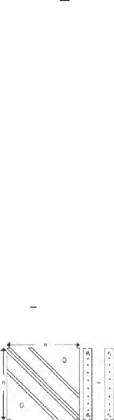
From the entire set of equations obtained for both the surface and subsurface
nodes, one gets a matrix equation of the form AΦ = B (Fig. 15.5)
AΦ= B (15.20)
Since potential is computed in a two dimensional xz plane, the source and the
sink extend to infinite distance along the y directio n . Therefore these sources
are line sources. For converting these potential due to a line source and sink
to potentials due to a point source and sink, integral transform must be used.
15.2.5 Inverse Fourier Cosine Transform
For two-dimensional earth models, the potentials computed are for line source
when it remains independent of one co-ordinate axis. The resistivity distribu -
tion is assumed to be a function of only two co-ordinates (x, z). Since three
dimensional point source is used, the problem cannot be treated purely as
three-dimensional. It is necessary to remove the source variation along y direc-
tion by fourier transformation in order to solve the two-dimensional problem.
Assuming symmetry along y = 0, the potential variations may be transformed
by the application of inverse fourier cosine transformation. We define
φ (x, y, z)=
2
π
∞
0
φ (x, λ, z) Cos(λy)dλ (15.21)
A Φ = B
Fig. 15.5. Curtoon of a system matrix in finite difference problem using Poisson’s
equation and showing sparsity
15.2 Finite Difference Formulation/Direct Current Domain 481
On the y-axis or when y = 0, we get
ϕ (x, o, z)=
2
π
∞
0
φ (x, λ, z)dλ (15.22)
where λ is the integration variable. Many authors (Mwenifumb o (1980), Sasaki
(1982 ), Dey and Morrison (1976), Pridmore (1978)) have used 5 to 7 values of
integration variables λ between 0 and some finite value to bring down the upper
limit of integration form ∞. Behaviour of this integr al is studied in greater detail.
It was found that better results are obtained if the λshave a gaussian distribu-
tion between the limits of integral. Therefore the principle of gauss quadrature
integration is followed for evaluating (15.21). Using this pro cedure the effect of
different sets of λ valu es on the accuracy in computing potentials with distance
from the source in the working area is examined in detail.
It is observed that, within fixed limits of integration, higher the number
of λ values, greater will be the distance of the point from the source till the
analytical and computed values of p o tential have a considerable agreement.
For example, the distance will be 50 units, 8 units and 2.5 units for sets with
11, 7 and 3 λ values respectively.
15.2.6 Calibration
The discrepancy between numerical and analytical solutions must be min-
imised comparing the responses fo r the bodies of simpler ge ometries. At this
stage the program source code will be ready for op eration.
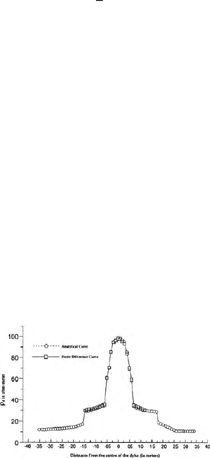
Figure 15.6 shows a two electro de apparent resistivity profile over a vertical
dyke of higher re sistivity obtained using finite difference source code. Values
are compared with those obtained using analytical formulae based on image
theory (see Chap. 11).
Fig. 15.6. Resistivity two electrode profile across a vertical dyke; comparision
b etween the finite difference model and that obtained with those obtained from
analytical solution
482 15 Numerical Methods in Potential Theory
15.3 Finite Difference Formulation Domain
with Cylindrical Symmetry DC Field Borehole
Geophysics
15.3.1 Introduction
In this section finite difference modelling in DC field for a domain of cylindri-
cally symmetric structure is given h ighlighting some difference in the bound-
ary conditions, geometry of the model and grid system used. In this model
the domain extends from r = 0 to r = ∞ and z = ±∞ whereristheradial
distance from the axis of the cylinder and z is the vertical distance of both
upward and downward boun d aries. Discretization of one half of the r-z plane
for solution of the boundary value problem is only needed. That reduces the
computer storage space considerably. In this section a few more points on
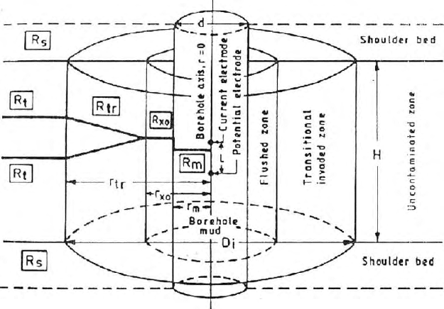
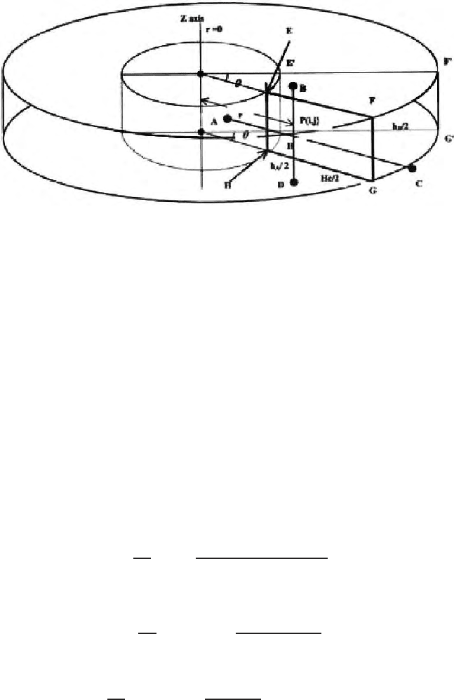
finite difference modelling are discussed. Figure (15.7) shows the geometry of
a problem in a zone of cylindrical symmetry. In this problem the Neumann
boundary condition is satisfied on the axis of a cylindrical domaim. Dirichlet
boundary conditions will be met at r = ∞ and z = ± ∞. The model is set
up in a c ylin drical co-ordinate system. A point source, located in a radially
symmetric environment, generate the potential field.
The proposed medium, with certain structures, is discretized and divided
into rectangular blocks by using vertical and horizontal grid lin es, whose
Fig. 15.7. Borehole model with coaxial cylindrical symmetry; coaxial cylindrical
zones respectively show the borehole mud, flushed zone, invaded zone, uncontami-
nated zone and shoulder beds on top and bottom (Anon 1972)

15.3 Finite Difference Formulation Domain with Cylindrical Symmetry 483
mutual separations increased exponentially, b oth in the vertical and r adial
directions. Radial variation of resistivity in one of the coaxial cylindrical shells
is simulated in FD modelling.
15.3.2 Formulation of the Problem
In a cylindrical co-ordinate system with radial symmetry, the starting Pois-
son’sequationiswrittenas
∂
∂r
σ
∂ϕ
∂r
+
∂
∂z
σ
∂ϕ
∂z
+
1
r
σ
∂ϕ
∂r
+ q = 0 (15.23)
where, σ = σ (r, z) and ϕ = ϕ (r, z). This relation represents an elliptic second
order differential equation and defines the electric potential due to a current
source in a medium. The quantity q must be interpreted as a variable current
density in a typical 3-dimensional model, which is reduced to 2-dimension in
the cross section considering rad ial symmetry.
15.3.3 Boundary Conditions
For finite difference modeling, the infinite medium is made finite by placing
an artificial boundary. Figure (15.7) shows one such boundary in vertical
cross section of an earth model. The medium is discretized by dividing it into
number of rectangular cells with vertical and radial grids. The intersection
points of the grid are called pivotal or nodal points.
Pivotal points which lie on the axis of symmetry or the borehole axis
i.e., the boundary through the points P
(1,1)
and P
(
i
max
′
1)
should follow the
boundary conditions i.e.,
∂ϕ(r, z)
∂r
|
r=0
= 0 (15.24)
2) and ϕ(r, z) = 0 when r →∞and z →±∞
15.3.4 Grid Generation for Discretization
The domain has been discretized using vertical and radial grids. As the model
is axially symmetric, only one half of the vertical section, i.e., r ≥ 0iscon-
sidered. It is necessary that the grids to b e finely spaced near the current
source (s) as the variation of potential around the source is maximum. As one
moves away from the current source in any direction, the change in poten-
tial gradually diminishes. Hence at points far from the current source, the
grids may be much coarser. It is convenient and justified to increase the grid
spacing exp onentially with distance from the current source. Co-ordinate o f
a node can be conveniently denoted by (i, j). The node, corresponds to ith
row and jth column can be denoted by P
(i,j)
. j = 1 corresponds to borehole
axis , r = 0, i=i
max
correspond s to the upper and lower boundaries in the
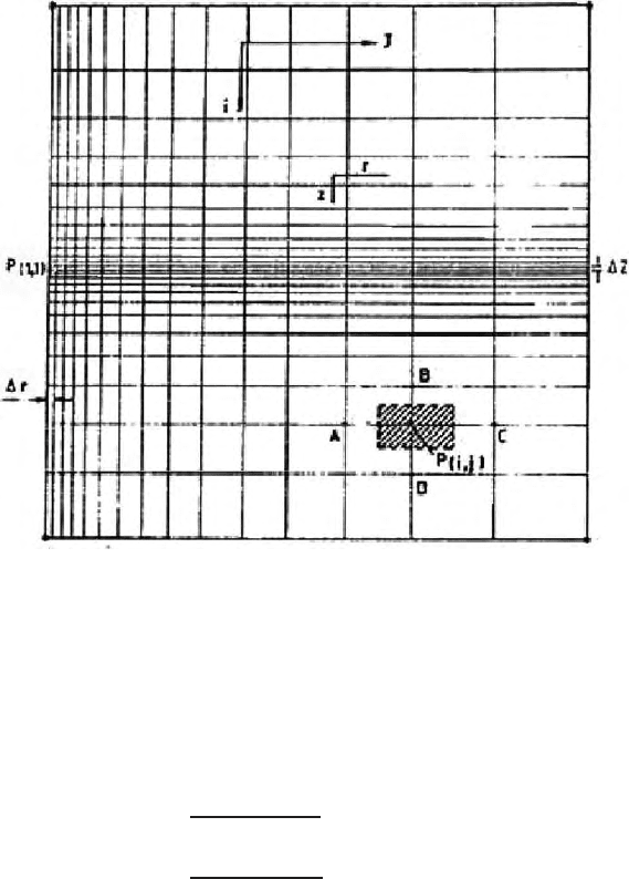
484 15 Numerical Methods in Potential Theory
Fig. 15.8. Expanding grid for finite difference modelling; P
1,1
,the location of source
point
vertical plane and j = j
max
corresponds to the radial boundary. The current
point source is lo cated at a point P
(1,1)
(Fig. 15.8).
Location of any pivotal point P
(i,j)
canbeexpressedinanexpandinggrid
system as (Mufti 1976)
r(i, j) =
∆r
a
j−1
− 1
a −1
for j = 1 to j
max
z(i, j) =
∆z
b
i−1
− 1
b −1
for i = 1 to i
max
(15.25)
where, a and b are the expansion ratios and ∆r a nd ∆z are the smallest spacing
in the radial and vertical directions respectively. The choice of grid expansion
can be determined by trial and error on the basis o f desired accuracy and
computational efficiency.
15.3.5 Finite Difference Equations
We can consider arbitrarily chosen element P
(i,j)
from the grid system shown
in Fig. (15.9). It’s four immediate surrounding neighbourhood pivotal points
areA,B,CandDdenotedbyP
(i,j−1)
′
P
(i−1,j)
′
P
(i,j+1)
and P
(i+1,j)
respectively.
15.3 Finite Difference Formulation Domain with Cylindrical Symmetry 485
Fig. 15.9. Enlarged view of a rectangular cell in a ring element
Distance from P
(i,j)
to these neighbours can be denoted as h
A
′
h
B
′
h
C
′
h
D
′
.
P
(i,1)
points fall on the borehole axis and are used as locations for current
and potential electrodes on the basis of the required position of which P
(1,1)
is the position of the current electrode. Figure 15.9 is a vertical section of a
three dimensional model. It only represents a slice of the earth and must be
rotated through 360 degrees to represent the actual setup. The 3-dimensional
space is divided into circular ring elements, which have rectangular cross sec-
tions. Figure 15.9 shows a ring disc volume element associated to the nodal
point P
i,j.
. Because of axial symmetry, these r in g elements can be viewed as
rectangular element in the section plane, which reduces the model to 2-D.
Figure (15.9) shows a node P
(i,j)
along with it’s four neighbours. The radial
distance of P
(i,j)
from the b orehole axis (r = 0) is r. Point P
(i,j)
represents the
rectangular element EFGH, covering an area of (h
A
+h
C
)/2 ×(h
B
+h
D
)/2in
the vertical section. ϕ
i,j
at the point P
(i,j)
in terms of its neighbouring nodal
points can be derived. On account of the central difference formula, the fol-
lowing approximations are valid at the point P. The difference equation can
be written as
∂ϕ
∂r
i,j
=
ϕ
i,j+h
C
/2
− ϕ
i,j−h
A
/2
h
A
+ h
C
. (15.26)
Therefore, for the point (i, j+h
C
/2), it can be expressed as
∂ϕ
∂r
i,j+h
C
/2
=
ϕ
i,j+h
C
− ϕ
i,j
h
C
. (15.27)
Hence,
σ
∂ϕ
∂r
i,j+h
C
/2
=
σ
i,j+h
C
/2
h
C
(ϕ
i,j+h
C
− ϕ
i,j
) . (15.28)
Similarly for the p oint (i, j −h
A
/2), one gets,

486 15 Numerical Methods in Potential Theory
σ
∂ϕ
∂r
i,j−h
A
/2
=
σ
i,j−h
A
/2
h
A
(σ
i,j
− ϕ
i,j−h
A
) . (15.29)
Here, σ
i,j+h
C
/2
and σ
i,j−h
A
/2
can be expressed as
σ
i,j+h
C
/2
=
σ
i,j
+ σ
i,j+h
C
h
C
(15.30)
and
σ
i,j−h
A
/2
=
σ
i,j
+ σ
i,j−h
A
h
A
(15.31)
where, σ
i,j
′
σ
i,j+h
C
and σ
i,j−h
A
are the conductivity values assumed at the
pivotal points P
(i,j)
′
P
(i,j+h
C
)
or P
(i,j+1)
′
and P
(i,j−h
A
)
or P
(i,j−1)
. Other values
of σ associated with the subsequent equations can be calculated in the same
way. For discr etization of the earth model, conductivity value is assigned to
each element or cell. Since conductivity and resistivity have reciprocal relation
(σ =1/ρ), therefore, the assigned value at the nodal resistivities can be
changed to nodal co nd uctivi ties.
Applying central difference formula once, one gets
∂
∂r
σ
∂ϕ
∂r
i,j
=
2
h
A
+ h
C
)
σ
∂ϕ
∂r
i,j+h
C
/2
−
σ
∂ϕ
∂r
i,j−h
A
/2
*
. (15.32)
Considering (15.28) to (15.31), (15.32) can be expressed as
∂
∂r
σ
∂ϕ
∂r
i,j
=
2
h
A
+ h
C
σ
i,j+h
C
/2
h
C
(ϕ
i,j+h
C
− ϕ
i,j
)
−
α
i,j−h
A
/2
h
A
(ϕ
i,j
− ϕ
i,j−h
A
)
. (15.33)
Proceeding in the same fashion, generalized self adjoint finite difference
approximation of the differential equation (15.33) can be represented as
2
h
A
+ h
C
σ
i,j+h
C
/2
h
C
(ϕ
i,j+h
C
− ϕ
i,j
) −
σ
i,j−h
A
/2
h
A
(ϕ
i,j
− ϕ
i,j−h
A
)
+
2
h
B
+ h
D
σ
i+h
D
/2,j
h
D
ϕ
i+h
D
′
j
− ϕ
i,j
−
σ
i,j−h
B
/2,j
h
B
ϕ
i,j
− ϕ
i,h
B
′
j
+
σ
i,j
r
i,j
(h
A
+ h
C
)
[ϕ
i,j+h
C
− ϕ
i,j−h
A
]+q
i,j
= 0 (15.34)
where, ϕ
i,j−h
A
′
ϕ
i−h
B
′
j
′
ϕ
i,j+h
C
andϕ
i+h
D
′
j
are the potential function associ-
ated to the P
i,j−1
′
P
i−1,j
′
P
i,j+1
and P
i+1,j
nodal points.
From (15.34) after separating out the co-efficient of φ,onegets
−α
C
ϕ
i,j+h
C
− α
A
ϕ
i,j−h
A
− α
D
ϕ
i+h
D
′
J
− α
B
ϕ
i,h
′
B
j
+ α
P
ϕ
i,j
= q
ij
(15.35)

15.3 Finite Difference Formulation Domain with Cylindrical Symmetry 487
where,
α
C
=
2
(h
A
+ h
C
) h
C
'
σ
i,j+h
C
/2
(
+
σ
i,j
(h
A
+ h
C
) r
i,j
α
A
=
2
(h
A
+ h
C
) h
A
'
σ
i,j−h
A
/2
(
−
σ
i,j
(h
A
+ h
C
) r
i,j
α
B
=
2
(h
B
+ h
D
) h
B
'
σ
i−h
B
/2,j
(
(15.36)
α
D
=
2
(h
B
+ h
D
) h
D
'
σ
i−h
D
/2,j
(
α
P
= α
A
+ α
B
+ α
C
+ α
D
.
Above (15.35) gives the potential relation for an arbitrary inside pivotal point
P
i,j
in the discretized domain.
In (15.23) the term
1
r
σ
∂ϕ
∂r
, contains a division by r. That leads to mathe-
matical indeterminacy as r → 0 on the borehole axis. This algebraic singularity
is avoided assuming [Mufti (1978, 1980)].
lim
r
→ 0
1
r
∂ϕ
∂r
=
∂
2
ϕ
∂r
2
r=0
(15.37)
From the (15.23), the generalized expression for evaluating the potential
along the axis of symmetry changes to
∂
∂r
σ
∂ϕ
∂r
+
∂
∂z
σ
∂ϕ
∂z
+ σ
∂
2
ϕ
∂r
2
+ q =0. (15.38)
Finite difference equivalent of the (15.38) can be written as
2
h
A
+ h
C
σ
i,j+h
C
/2
h
C
(ϕ
i,j+h
C
− ϕ
i,j
) −
σ
i,j−h
A
/2
h
A
(ϕ
i,j
− ϕ
i,j−h
A
)
+
2
h
B
+ h
D
σ
i,j+h
D
/2,j
h
D
ϕ
i+h
D
′
j
− ϕ
i,j
−
σ
i−h
B
/2,j
h
B
ϕ
i,j
− ϕ
i−h
B
′
j
+
2σ
i,j
h
A
+ h
C
1
h
C
(ϕ
i,j+h
C
− ϕ
i,j
) −
1
h
A
(ϕ
i,j
− ϕ
i,j−h
A
)
+ q
i,j
=0. (15.39)
The nodal points, lo cated on the borehole axis, have the value r = 0, and
corresponds to the first column of nodes i.e., for j = 1. Hence the co-ordinates
of the pivotal points will be P
(i,1)
. For calculation of p otential on the axis of
symmetry, a fictitious column of element parallel to the axis of symmetry at
the left of (i, 1) is considered and intro duced, such that
h
A
=h
C
(15.40)
and
σ
i,1+h
C
= σ
i,1−h
A
. (15.41)

488 15 Numerical Methods in Potential Theory
Elements fall on this axis (i, 1) should satisfy the Neumann boundary condi-
tion
∂ϕ
∂r
r=0
=0
and this is possible only if
ϕ
i,1+h
C
= ϕ
i,1−h
A
. (15.42)
Putting all these assumptions described above in (15.39) and separating out
the coefficient of ϕ,onegets
− α
C
ϕ
i,1+h
C
− α
D
ϕ
i+h
D
′
1
− α
B
ϕ
i−h
B
′
1
+ α
P
ϕ
i,1
= q
i,1
(15.43)
α
C
=
2
h
2
C
'
σ
i,1+h
C
/2
+2σ
i,j
(
α
B
=
2
(h
B
+ h
D
) h
B
'
σ
i−h
B
/2,1
(
(15.44)
α
D
=
2
(h
B
+ h
D
) h
D
'
σ
i+h
D
/2,1
(
α
P
= α
B
+ α
C
+ α
D
.
Equations (15.34) to (15.43) are the main finite difference approximations,
which can be solved for the potential expression ϕ (r, z). In practical problems,
a linear equation should be formed using the relations mentioned. Potential
at each node must be expressed in terms of its immediate neighbour and set
of coefficients α
A
′
, α
B
′
, α
C
′
, α
D
and α
P
are evaluated. Systematic ordering
of the grid points develops a sparse conductivity coefficient matrix, which is
solved for evaluation of potential field at a desir ed location using a suitable
matrix solver.
15.3.6 Current Density Factor q at the Source
In this two dimensional borehole d.c. resistivity forward problem involving
radial symmetry, the source is assumed to be a p oint source and located
along the axis of symmetry which coincides with the borehole axis. It is also
stated that in the expanding grid system the source is considered at the po int
P
(1,1)
from where the grid expands exponentially on both the sides in the
vertical (z) and radial (r) directions. The volume associated with the piv-
otal point is a cylinder of radius h
C
/2 and height (h
B
+h
D
)/2. Figure 15.10
shows such a volume element a ssociated to any of pivotal points that lie
on the axis of symmetry. The volume of this cylinder can be written as
π
h
C
2
2
h
B
+h
D
2
. Borehole axis is a boundary and Neumann boundary con-
dition is satisfied here. The approximation is made considering a fictitious
grid parallel to this axis of symmetry which has already been stated in the
previous section. Let a current of constant strength I be emitted from the