Roll Forming Handbook / Edited by George T. Halmos
Подождите немного. Документ загружается.


The removal and reinstallation of such a
split spacers may take less than 1min after
the operator-side stand is pulled out by a
shortdistance.
Split spacers are moreexpensivethan
one-piecespacers, but the extra cost can be
quickly recovered by reducing the non-
productive time.
5.7.5 Shims
(a) One-Piece Shims .Shims are made out of
hard“shim”stock. The bores can be about
0.005 to 0.060 in. (0.13 to 1.5 mm) larger
than the shaft diameters. Keyways should
be cut into the shims. The outside diameter
should be aminimum 1in. (25 mm) larger
than the bore. If the shims or spacers are
placed between largediameterrolls
(Figure 5.83), then their O.D. should be
considerably larger to avoid excessive tilt-
ing or bending of the rolls.
Shimsshouldbeavoided wherever
possible. Shimscannotbeproperly
marked, and they can be easily mixed up
and lost. The edges of the thin shims can
easily fold over,creating aspace of double
shim thickness between rolls.
(b) Split Shims.Quick-change shims can be easily made by splitting the shims at one side as shown in
Figure5.84a. The use of horseshoe shims (Figure 5.84b) is definitely not recommended for the
reasons explained in Section 5.7.4b.
5.8 Calculating Strip Width
5.8.1 Straight and Curved Elements
To calculate the blank size, or in other words, strip or coil width, the final cross-section is divided into
straight and curvedelements. Forblank size calculation purpose, it is assumed that the lengths of the
straight elements do not change during roll forming. Calculating the length of acurved element by using
the length of its center line (theoretical neutral axis) gives an incorrect, larger starting width than the
required width.
Foraccurate strip width calculation, it is assumed that the theoretical neutral axis of the bent element
moves from the half thickness location closer to the inside (Figure5.85a). The new location of the
“relocated” neutral axis is expressed by the bend allowance(“ k ”). Forexample, the “ k ”factor for alow
carbon, annealed steel having abend radius equal to the material thickness ð r : t ¼ 1 Þ is about 0.33. This
means that the new neutral axis, used to calculate the blank size, will be 0.33 times the metal thickness
distancefrom the inside surfaceofthe bent element instead of 0.5 times.
In reality,the material also gets thinner at the corners as shown in Figure 5.85b. The stresses created by
the bending are over the yield limit and they cannot change abruptly to zerostress at the end of the
curvedelement. The changeover is gradual, which means aslight thickness change in the straight element
too.However,the empirical “ k ”factor used for the curvedelement provides an accurate blank size (strip
width), with the assumption that the length and the thickness of the straight element are not changing.
FIGURE 5.83 Between large diameter rolls, large
diameter shims or spacers should be used to avoid tilting
of the rolls.
Roll Forming Handbook5 -52

The main influencing factors on the empirical
“ k ”factor are the inside radius, material thickness,
and mechanical properties of the metal.
Thelargerthe r : t ratio, thecloserthe “ k ”isto0.5.
The larger the yield and tensile strength and the
lowerthe elongation, the closer the “ k ”isto0.5.
The “ k ”factor has been used to calculate blank
size of press brake-formed parts for along time.
Therefore, alarge number of equations and tables
are available to calculate the length of the bend
sections. Almost all tables are different and give
slightly different results. Most calculated blank
sizes are very close to the actual ones, but the final
blank size has to be proven by testing.
An equation to establish the “ k ”factor devel-
oped by the author and used in the RollFormer’s
Guide software is shown in Equation 5.6:
k ¼ 0 : 567
R
i
t
þ 0 : 25
1 : 2
R
i
t
þ 1
1 þ
Y
2 : 5
250U
1 : 41
!
ð 5 : 6imperialÞ
where
R
i
¼ inside bend radius (in.)
t ¼ metal thickness (in.)
Y ¼ yield strength (ksi)
U ¼ tensile strength (ksi)
5.8.2 Manual Calculation of Strip
Width
Each cross-sectionconsists of straight and curved
element. The manual calculation of the strip
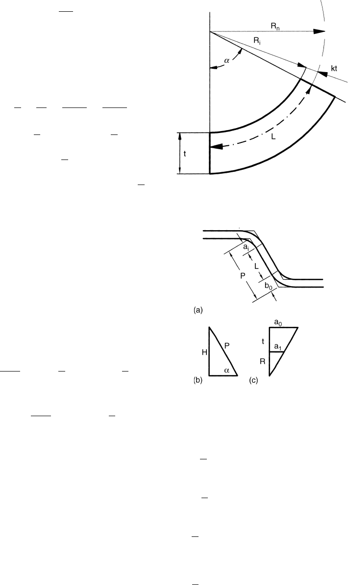
width required for acurvedelement is shown
below (see Figure 5.86).
t ¼ thickness
k ¼ bend allowance
R
i
¼ inside bend radius
R
n
¼ neutral axis radius
R
n
¼ R
i
þ k
t
L ¼ length of the bent element
a
¼ angle of bending in degrees
L ¼ 2 R
n
a
360
p
L ¼ 2 ð R
i
þ ktÞ
a
360
p
FIGURE 5.84 Horseshoe shims are not recommended,
but split shims can be used.
FIGURE 5.85 The “ k ”factor used in calculations of
blank sizes compensate for the actual change of length at
the bend lines.
Roll Design 5 -53
L ¼
p
180
ð R
i
þ ktÞ
a
The equation to calculate the strip width “ L ”
required for abent element is:
L ¼ 0 : 0174533ð R
i
þ ktÞ
a
ð 5 : 7 Þ
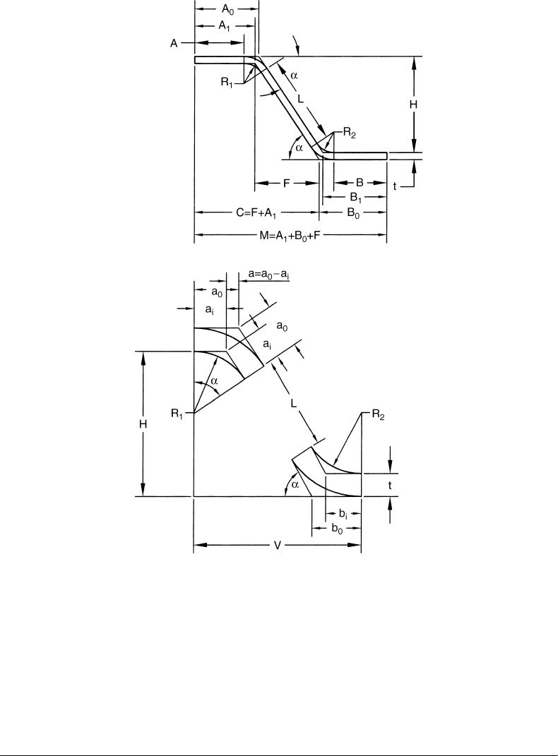
If H and
a
are given (Figure5.87a–c)
tan
a
2
¼
a
i
R
1
¼
a
o
R
1
þ t
¼
b
o
R
2
þ t
a
i
¼ R
1
tan
a
2
b
o
¼ðR
2
þ t Þ tan
a
2
¼ a
o
a
i
þ b
o
¼ tan
a
2
ð R
1
þ R
2
þ t Þ
if R
1
¼ R
2
; then a
i
þ b
o
¼ð2 R þ t Þ tan
a
2
During strip width calculation, it is assumed that
thelengths of thestraight elementsare not
changing during forming. However,ifthe lengths
of the straight elements are not shown on the
drawings, they havetobecalculated. Forthe
lengthymanual calculations, see atypical cross-
section shown in Figure5.88 and the equations
below.
If R
1
¼ R
2
¼ R ; then a
i
¼ b
i
and a
o
¼ b
o
V ¼ L cos
a
þð2 R þ t Þ sin
a
ð 5 : 8 Þ
If R
1
– R
2
L ¼
H
sin
a
2 R
1
tan
a
2
2 ð R
2
þ t Þ tan
a
2
ð 5 : 9 Þ
If R
1
¼ R
2
¼ R
L ¼
H
sin
a
2 ð 2 R þ t Þ tan
a
2
ð 5 : 10Þ
If H ; A
o
; and
a
are given, and A ¼ A
o
2 a
o
A ¼ A
o
2 ð R þ t Þ tan
a
2
ð 5 : 11Þ
If H ; B
o
; and
a
are given
B ¼ B
o
2 ð R
2
þ t Þ tan
a
2
ð 5 : 12Þ
If H ; A
i
; and
a
are given, and A ¼ A
i
2 a
I
A ¼ A
i
2 R
1
tan
a
2
ð 5 : 13Þ
and
B ¼ B
1
2 R
2
tan
a
2
ð 5 : 14Þ
FIGURE 5.86 Calculating the length of curved element
(“L ”) for computing strip width.
FIGURE 5.87 Calculating blank size.
Roll Forming Handbook5 -54
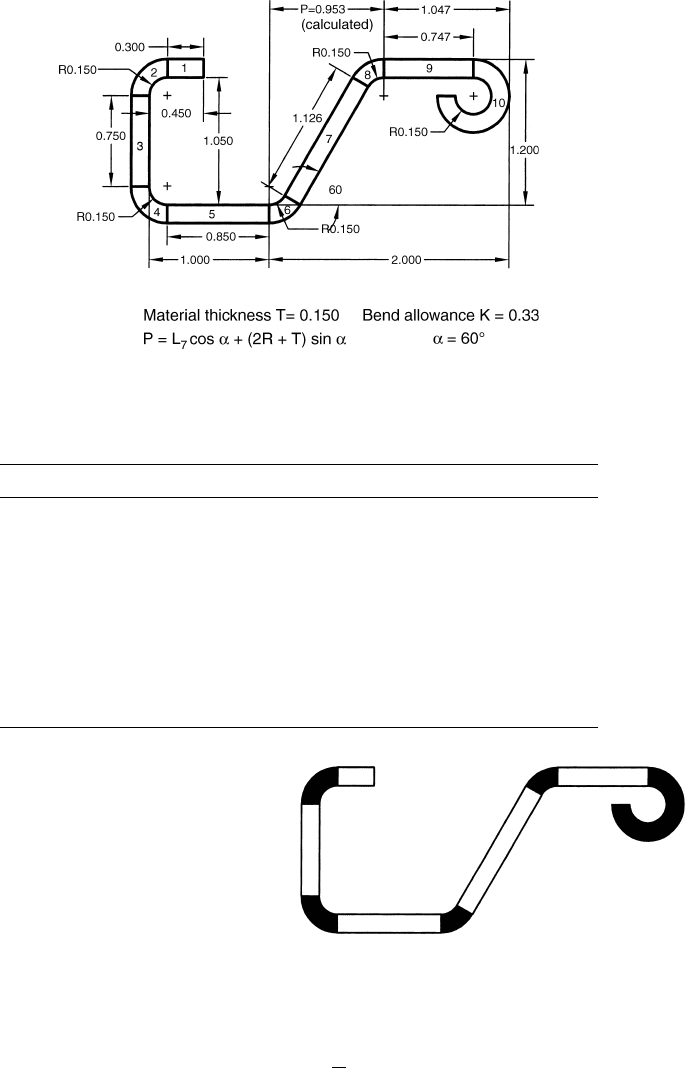
5.8.3 Manual Calculation of Blank Size: Example
Figure5.89 shows atypical cross-section prepared for manual blank size calculation. The corresponding
calculations are shown in Table 5.4.
With the widespread application of computers and CAD software, these time-consuming manual
calculations are less and less frequently required.
5.9 Bend Lines
5.9.1 Bent Elements
The cross-section of rollformed parts can be divided into straight and curvedelements (Figure
5.90). The curved elements from the original flat position can be bent in different ways. They can
be formed with constant arc length or with constant radius or with amixture of constant arc length
and constant radius.
FIGURE 5.88 Schematics illustrating blank size calculations.
Roll Design 5 -55
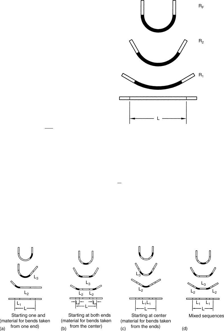
5.9.2 Constant Arc Length
Forming
Thefulllengthofthe bent element ð L Þ
designated for the bending is formed at each
pass to aprogressively smaller and smaller radius
(Figure5.91).
Oncethe “ L ”iscalculated (Equation 5.7), the
inside radius ( R
i
)ateach pass can be calculated
from the total angle of the bend (
a
)atthat pass.
(For details, see Figure 5.86 where“k ”isthe bend
allowanceand “ t ”isthe thickness of the material).
R
i
¼ 57: 2958
L
a
2 kt ð 5 : 15Þ
5.9.3 Constant Radius Forming
One or moresegments of the element to be bent are formed to the final radius at each pass (Figure5.92).
The roll designer selects the segment of the arc element, which is bent in aspecific pass. The segment to be
FIGURE 5.89 Manual blank size calculation of across-section.
TABLE 5.4 Manual Blank Size Calculation
#Calculation Length
10.450-R 0.300
20.017453*(R þ k*T)*90 0.314 (5.7)
31.05-2*R 0.750
40.017453*(R þ k*T)*90 0.314
51-R 0.850
60.017453*(R þ k*T)*60 0.209
71.2/sin60-(2*R þ T)/tg30 1.126 (5.10)
80.017453*(R þ k*T)*60 0.209
92-P-R-T (P ¼ 0.953) 0.747 (for “P,” see Figure5.91)
10 0.017453*(R þ k*T)*270 0.940
Total blank (strip) width 5.759
FIGURE 5.90 All cross-sections are divided into straight
and curved elements.
Roll Forming Handbook5 -56
bent can be at one end of the curvedelement,
formingthe adjacent straight piecetothe
finished radius in the next pass and so on (Figure
5.92a). The bending maystartatboth ends of the
element to be bent, then forming the adjacent
ones and finally finishing up at the center (Figure
5.92b). Another possibilityistoform the center
parttothe finished radius, then forming the
adjacent segments on the next pass and so on
until the bending of the element to the specified
angle is completed (Figure5.92c), or the bending
sequence of the elements can be mixed (Figure
5.92d).
The length of segment to be formed at each
pass can be calculated in the following way.
Total length of the element to be bent can be
calculated by using Equation 5.7
L ¼
p
180
ð R
i
þ ktÞ
a
if the total angle to the bent is
a
(Figure5.93)and
the bending angle increment from one pass to the
next pass is
b
; then the segment length ( L
1
)tobe
bent to the final R
i
is:
L
1
¼
b
a
L ð 5 : 16Þ
Example
If the final angle is 908 and the bend angle increase at agiven pass is 22.58 ,then the length of element to be
bent at that pass is (22.5 4 90)L or 0.25 times the total length of the curvedelement (Figure 5.93b). If it is
decided to bend the element at twoplaces in this pass, then each element will be bent by
22.5 4 2 ¼ 11.258 .Therefore, the length of each half element will be 0.125L (Figure 5.93c).
FIGURE 5.91 Constant arc bending in three passes (dark
sections are formed).
FIGURE 5.92 Constant radius bending in three passes.
Roll Design 5 -57
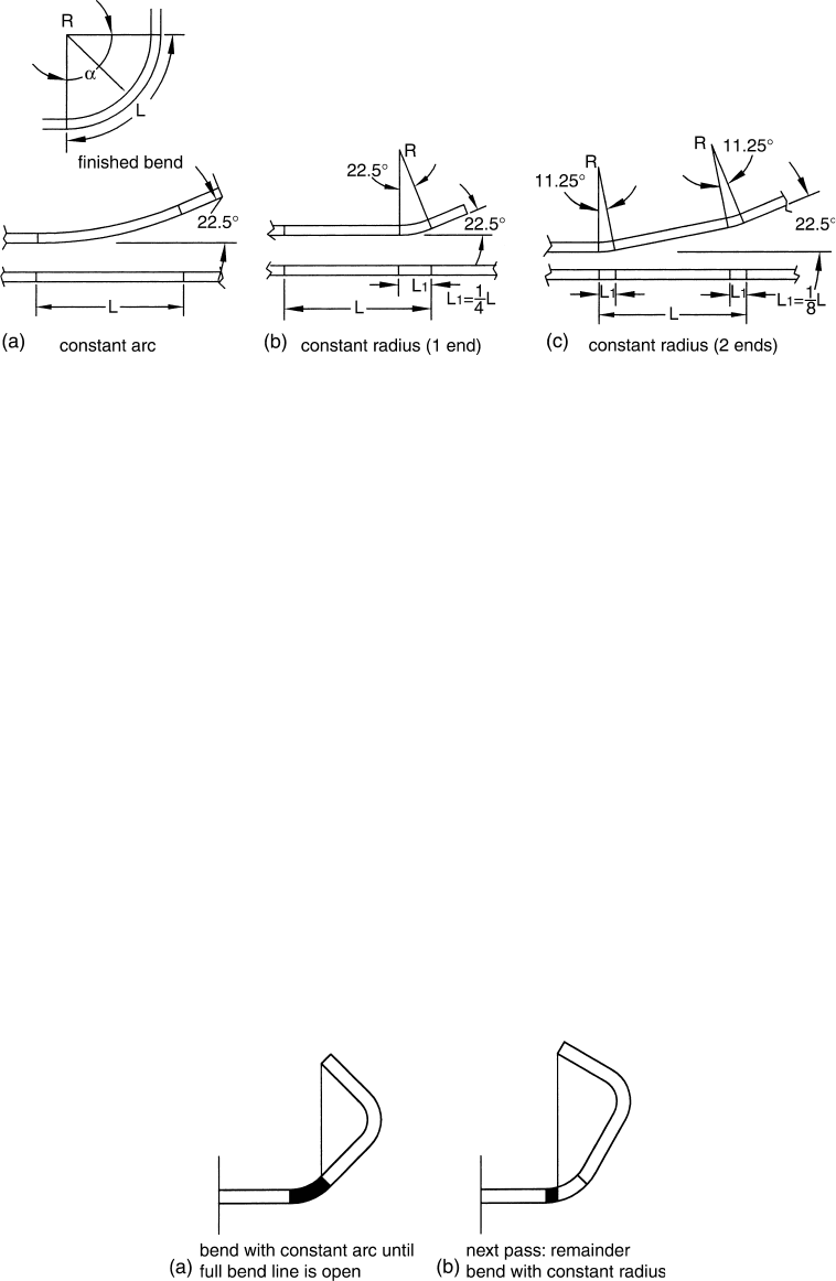
5.9.4 Mixture of Constant Arc Length and Constant Radius Forming
Occasionally,althoughrarely, the designer uses constant arc length up to the point wherearollcan fully
reachthe inside of the bend line, then switches to the constant radius for the next sequence of the bend
line (Figure5.94).
5.9.5 Which Method to Use
No straightforward rule exists to dictate which approach to take except in afew cases. Forexample, the
constant arc method is recommended when blind corners are formed. In ablind corner,the male die
cannot reachinto the inside of the bend line. Therefore, it is not possible to specify that only one segment
of the bend line should be formed to the specified radius.
Constant arc method is also favoredwhen several bend lines are formed at the same time, such as the case
with siding,roofing, and manyother sections. The larger radii used in the constant arc method allows a
“slip in”or“slip-out” of the material in the first few passes of forming, instead of trapping it with the
smaller,final radius.
In principle, constant radius bending can be used only when both the male and female rolls are in
contact with the bend line. Therefore, constant arc bending is recommended in all “free”bending cases.
The following two examples show twoproducts whereforming with constant radius has definite
advantages. The first one, Figure5.95ashows aproduct with very large radius (large r : t ). Using constant
arc method requires so much overbending at the last pass (Figure5.95b) that the section would not fit
into the mill. Using constant arc, each segment of the arc can be overbent apercentage of the total
FIGURE 5.93 Calculating the length of bent elements formed with constant arc or constant radius.
FIGURE 5.94 Forming with combination of constant arc and constant radius.
Roll Forming Handbook5 -58
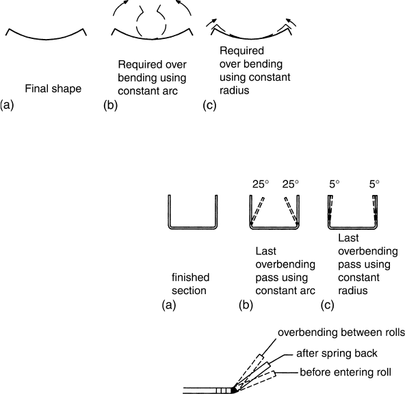
required overbending. Therefore,the last pass
overbend will only be the fraction of the total
overbend (Figure 5.95c).
The otherexampleshows ahighstrength
material exhibiting 258 springback formed into a
“U” channel. Using constant arc length forming,
after reaching the 908 ,a25 8 overbend would be
required. 258 overbend cannot be made in narrow
sections because the “legs” will touch each other.
If the forming is made in, say, 10 passes and
constant radius forming is used, then each arc
segment at each pass should be overbent by
25 4 10 ¼ 2.58 .This means that at the last pass
the overbend will need to be only 2.58 and not
258 (Figure5.96).
Choosing between constant arc and constant
radius, or using amixture of the two is up to the
designer and frequently is dictated by his/her experience. Therefore, recreating rolldrawings by
measuring the used, worn rolls, and “double guessing” the method used by the designer of the original set
of rollsismuch more complex, difficult and time consuming than to design acomplete set of new rolls.
5.9.6 False Bend
Occasionally,itisnecessarytobend and then restraighten elements which will eventually be straight after
roll forming are completed. This method is applied during false bending.
*
When aradius is “flattened” at alater stage of forming (Figure5.97a,b)
*
To reachotherwise hidden bend lines (as shown in Figure5.98a)
*
When the leg angles are adjusted by this type of bending (Figure5.98b–d)
*
When it is anticipated that the forming of “legs” would also bend the adjacent shortstraight
element especially in the case of thick material (Figure5.99)
False bends require unusual blank size calculation. During the bend, the material stretches. The increase
of the element length can be calculated by using the “ k ”factor.However,when the same element is
straightened, it does not “contract.”Inthe opposite, it stretches again. Therefore, afinished width of a
straight element containing afalse bend made with asharp radius will be slightly longer than before
bending and flattening.
To compensate for this width increase caused by the false bend, aslightly smaller than the normally
applied “ k ”factor should be tried for the first test. If the false bend is made with large radius and the “ k ”
factor is 0.5 or close to it, adjustment in the blank width calculation is not required. The properly calculated
blank for asection withsharp false bend will be slightly less than the same section without false bend.
FIGURE 5.95 Forming large radius with constant arc and overbending at each pass requireless overbending at the
last pass then forming with constant arc.
FIGURE 5.96 Overbending UHSS “U” channel at each
pass using constant radius method.
Roll Design 5 -59

5.9.7 Side-Rolls
In addition to the conventional forming rolls mounted on parallel, horizontal shafts, side-rolls are
frequently used for manyforming operation. Side-rolls havesimilar functions as the main rollsand are
equally important. Side-rolls havehad abad reputation in the industryfor along time. The reason is that
the usually conservativeroll designers have aimed to complete the forming with the main rolls. If tool
testing revealed that additional forming or guiding was required, then often the setup man tried to cure
the problem in the least expensiveway.Flimsy side-rollstands withcam followers frequently made the
product acceptable. However,itiscumbersome to properly setup and adjust these side-roll stands.
Side-rolls do the same work as the main rolls. Side-rolls are extensively and successfully used in tube
forming and should be morewidely used in roll forming.Side-rolls should be incorporated in the original
roll design. The forming withside or cluster-rolls should be aseparate “pass” in the flower diagram.
FIGURE 5.97 “False bend” is flattened at alater pass.
FIGURE 5.98 Angle / can be adjusted by the degree of “flattening.”
FIGURE 5.99 Eliminating cross-bow with false bend in narrow,closed sections formed from thick material.
Roll Forming Handbook5 -60

The side-roll stands should be of good quality, easily,and accurately adjustable. Side-rolls are repeatedly
used to control variable springback, and often they are adjusted more frequently then the main rolls.
There is no rule that all shafts must be in horizontal position. Shaft positions should be selected for
optimum forming, reaching inside and enveloping the outside of the bends and to minimize speed
differential between the rolls and the formed sections. “Free-running”rolls will adopt the speed of the
strip,will reduce the friction, and hence will less likely to scratch the surface of the product.
Side-rolls, with afew exceptions, are not driven. Therefore, they must be used in conjunction with
driven main rolls. However,ifthe “free-running” nature represents arestriction,then it is recommended
to drivethe side-rolls.
Typical side-rolls are shown in Figure 5.100a–fand Figure5.26.Side-rolls are usually placed between
main passes. To be effective and to avoid undue residual stresses, the horizontal distances between the
main passes and the side-rolls should be sufficiently long.Itisacommon mistaketo“squeeze” side-rolls
between the main passes already having ashorthorizontal distance(Figure 5.101). This arrangement can
increase flare, create waviness, and other problems. Ideally,side-rolls should be positioned at the same
horizontal distanceasthe main stands.
FIGURE 5.100 Typical side-roll stand forming or overbending.(a, b, and c) “U” channels. (d) Hat section.
(Courtesy of Delta Engineering Inc.) (e) Lips. (Courtesy of Delta Engineering Inc.) (f)Building panel. (Courtesy of
Metform International Ltd.)
Roll Design 5 -61
