Qin Y. Micromanufacturing Engineering and Technology
Подождите немного. Документ загружается.


21
In-situ Testing of Mechanical
Properties of Materials
*
Fredrik O
¨
stlund, Karolina Rzepiejewska-Malyska, Laetitia Philippe,
Patrick Schwaller and Johann Michler
INTRODUCTION
The mechanical properties of small structures,
typically with dimensions within the range of a
few hundred microns down to sever al microns or
below, cannot simply be extrapolated from the
properties of bulk samples. This is due to two
effects. First, samples used for bulk mechanical
testing usually have dimensions which are much
larger than the micro-structural features, such as
grains or pa rticles. Second, mechanical behavior
is controlled by certain fundamental length scales.
For example, plasticity in met als involves the
motion of dislocations, which are hindered when
they try to pass between obstacles more closely
spaced than about 100 nm, and fracture in brittle
materials is initiated at flaws with a critical size of
several tens of micrometers [1]. The mechanical
properties of a material will fundamentally
change as the sample dimensions become smaller
than these fundamental length scales. It is there-
fore necessary to measure the mechanic al proper-
ties at a length scale comparable to the feature
sizes used in miniature or micro-electromechani-
cal devices. An example is the flow stress depen-
dence on pillar size in micro-compression experi-
ments shown by Uchic et al. [2], who performed
compression tests on Ni pillars ha ving different
diameters ranging from 40 mm down to 5 mm and
found that for the smallest samples the flow stress
is almost three times greater than for bulk Ni.
Accurate prediction of a material’s response
also requires an understanding of the fundamental
mechanisms of material deformation and fracture
in the micro- and nano-scale. It is therefore essen-
tial that small specimens, for instance for tensile
or compression testing, can be manufactured for
which appropriate handling and manipulation
techniques and equipment with appropriate load
and displacement resolution are available. Also it
has to be possible to observe the material under
load in-situ to study plastic-deformation and
crack-propagation mechanisms. The scanning
electron microscope (SEM) is an ideal platform
for in-situ mechanical testing, as it covers a mag-
nification range from 10 to 10
6
times, exhibits a
relatively large specimen chamber that can accom-
modate mechanical testing equipment and has
analytical capabilities for determining local chem-
ical composition and crystal structure.
In the following sections the reader will be
introduced to the peculiarities of integrating
materials testing within an SEM. The most popu-
lar techniques will be explored, i.e. miniaturized
tensile tests, compression tests and nano-indenta-
tion tests. Then the subject of image analysis
will be touched upon and finally a case study
CHAPTER
*
Figures 1, 2, 3 and Table 1, plus similarities in this
Chapter are re-produced with permission of MRS Jour-
nal of Materials Research.
331

combining the use of compressive- and tensile-
testing methods will be presented.
INTEGRATING A MECHANICAL
TESTING SET-UP IN AN SEM
At the time of writing there are no fully commer-
cialized products for in-situ materials testing on
the micrometer scale established on the market.
Integrating a mechanical testing set-up within an
SEM rais es some difficulties. In the following
some important details about this process will
be described.
It is of course necessary to use actuators and
load sensors that can deliver the required displa-
cements and measure the low loads encoun tered
at these scales. Additionally, a major limit is the
space available in an SEM chamber. This requires
that the actuators and sensors have small dimen-
sions. In particular, to achieve an optimal perfor-
mance of the SEM, the distance between the
objective lens of the SEM and the sample has to
be kept to a minimum. Typically, the optimal
working distance is between 2 and 5 mm.
The vacuum in the chamber also has to be
taken into account when designing a mechanical-
testing device. All elements of the device have to be
vacuum compatible, meaning that they do not
emit gas in vacuum. Special care should be taken
to avoid, for example, plastics and oil.
Note that some materials which normally do
not emit gas in vacuum can do so when exposed to
an electron beam. Teflon, for example, releases
fluorine when exposed to high energy electrons.
To facilitate the evacuation of the chamber, parts
that contain threads should have extra channels to
allow air to exit the components.
Magnetic materials should be avoided, since
their magnetic fields can affect the electron beam
of the SEM, resulting in a distorted image with bad
resolution. Similarly, electrical components must
have sufficient electrical shielding. All parts close
to the electron beam should also be conductive
and grounded in order to avoid electrical charging.
In particular, this applies to the tip used in com-
pression and indentation tests. Usually these tips
are made of diamond because of the high hardness
requirements. Pure diamond, however, is a very
poor electrical conductor. Therefore, boron-doped
diamond is a preferred choice. Even if these rules
are followed, the maximum resolution of the SEM
will generally not be achieved.
Note that not all experiments have to be per-
formed in-situ: cost and time have to be weighted
against gain of information. In addition, not all
materials can be test ed in-situ. The electron beam
might affect the sample by, for example, breaking
chemical bonds or the sampl e might become too
highly charged to be imaged. Charging problems
can often be solved by deposi ting a thin metal
layer on the samples before the testing. However,
this can potentially change the mechanical prop-
erties of the material.
TENSILE TESTS
Tensile testing is probably the most commonly
used standardized [3] method to determine the
mechanical properties of materials [4].Ina
typical tensile test a specimen having a small, uni-
form cross-section is strained until failure. The
deformation (increase in length) and applied load
are continuously measured during the whole
experiment. The applied engineering stress s is
defined by the load F divided by the initi al cross-
sectional area A
0
of the sample. The engineering
strain e is defined by the measured length change
Dl divided by the initial length L
0
:
s ¼
F
A
0
e ¼
Dl
l
0
ð1Þ=ð2Þ
A schematic representation of an engineering
stress/strain curve obtained this way is shown in
Figure 21-1.
From such a curve the following properties can
be inferred. The linear increase at low strain is an
elastic deformation that is described by Young’s
modulus E (the slope of the stress/strain curve).
The transition between elastic and plastic defor-
mation is defined by the 0.2% offset yield stress
R
p0.2
commonly used in materials technology. In
Figure 21-1 a straight line shifted by a strain of
0.002 is drawn parallel to the linear elastic part.
332 CHAPTER 21 In-situ Testing of Mechanical Properties of Materials
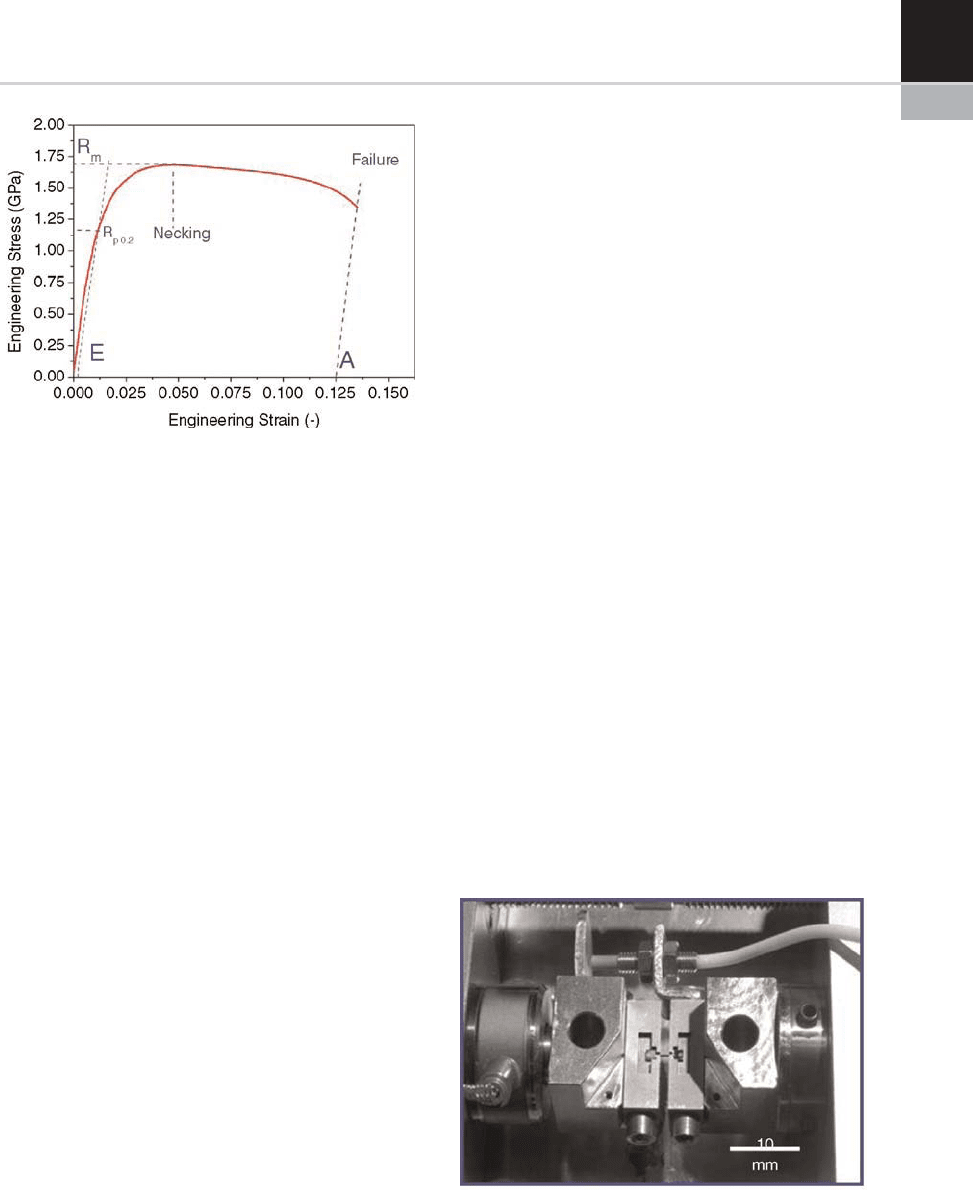
The intersection of this line with the stress/strain
curve is taken as the yield stress.
The tensile strength R
m
indicates the deforma-
tion where a necking of the sample starts. Finally,
the elongation at rupture A indicates the strain at
failure of the sample. The uniaxial deformation is
usually applied using a constant strain rate, i.e.
using a displacement control, in contrast to a load
control. This is because as a sample yields there
can be a decrease in the load. If that occurs with
load control the feedback system will try to re-
establish the load by increasing the strain. This
causes the sample to be rapidly deformed until
failure in an uncontrolled manner.
It is also worthwhile mentioning the difference
between engineering and true stress and strain
values. Engineering stress and strain are defined
by Eqns (1) and (2) as shown above. Both quan-
tities refer to the ini tial cross-section and initial
length. True stress s
true
and true strain e
true
values
take small changes of the deformation into
account starting from an instantaneous elastic or
plastic deformation. s
true
and e
true
can be calcu-
lated as follows:
s
true
¼ sð1 þ eÞ e
true
¼ lnð1 þ eÞð3Þ=ð4Þ
For samples in the millim eter range tensile
tests can be performed under an optical micro-
scope. If the samples are smaller, the higher r es-
olution of an SEM allows imaging. This is espe-
cially important if the images are used to extract
the strain.
From the image sequence, it is sometimes inter-
esting to observe the propagation of cracks
induced by the tensile strain and to correlate the
crack path or the crack type with other material
properties that can be inferred from SEM images.
Instead of imaging the sample using secondary
electrons, chemical mapping can be done using
energy-dispersive X-ray spectroscopy (EDX) and
the orientation of grains of the sample can be
recorded using electron backscatte r diffraction
(EBSD).
Due to the limited overall size of the test stage,
the sample dimensions also have to be small (typ-
ically only several millimeters length and of a few
100 micromete rs thickness). This means that sur-
face properties gain importance and rough surface
regions or a slightly different composition in the
surface region may influence the measured stress/
strain curves. The most critical issue, however, is
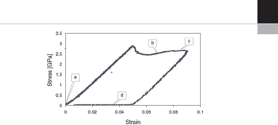
the correct fixing of the tensile test specimen.
Mechanical clamping may be unsuitable because
a deformation could already have been induced
prior to the actual test. A suit able solution is to use
sample holders having the ‘negative’ shape of the
specimen and to fit the specimen inside these hold-
ing forms: an example of this is shown in
Figure 21-2.
FIGURE 21-1 Engineering stress/strain curve for an NiCo
sample indicating the relevant quantities that can be
extracted from the curve (see text for the details).
FIGURE 21-2 A specimen for tensile testing positioned in
the sample holder of a tensile testing set-up.
CHAPTER 21 In-situ Testing of Mechanical Properties of Materials 333

Due t o the small dimensions of the tensile test
specimens, extensom eters or conve ntional strain
gauges cannot be clamped onto the samples.
However,theSEMimagescanbeusedtocalcu-
late strai n values. The quantitative evaluation of
the strain values from SEM images recorded dur-
ing the tensile tests, however, is difficul t. The
total elongation until fracture in the images is
often only a few pixels and specialized image
analysis routines allowing sub-pixel r esolution
have to be used to obtain reliable strain data:
this will be further discussed below. In contrast
to the displacement measurements, the load
measurements can be performed using conven-
tional load cells.
COMPRESSION TESTS
As an alternative and complement to tensile test-
ing, materials can be tested by compression tests.
This is also a method with very old roots and has
the advantage that the specimen does not have to
be attached at the ends of the testing set-up.
Compression tests are analogous to tensile tests:
a c ylindrical sample wi th uniform diameter is
compressed by applying an increasing force on
the ends until it fractures; typically starting
with a purely elastic region followed by plastic
deformation with strain hardening and finally
fracture. Throughout the compression the load
on the sample a nd the deformation are recorded.
Typically, these numbers are then converted
to engineering stress and strain and these are
plotted against each other, providing character-
ization of the material as described above for
tensile test s.
As for tensile tests, it is an advantage if the
actuators can be run with displacement control.
Although there is no necking phenomenon as for
tensile tests, crystalline samples can exhibit a load
drop at the onset of plasticity which can cause an
uncontrolled compression if load control is used.
In addition, the mechanical behavior of a material
is often dependent on the rate of compression,
making constant displacement more logical than
load control.
New load cells and piezo-actuators have
made it possible to perform compression tests
in the sub-micrometer scale [5] . Also vital for
this type of testing is the possibility to manufac-
ture rods or pillars using, for example, lithogra-
phy or focused ion beams (for an excellent
example of compression te sts on FIB-m achine d
metal pillars, cf. [2]).
Figure 21-3 shows an image series from a
compression test on a gallium arsenide pillar
of 4.2 mm diameter. This pillar was manufac-
tured by photolithography and reactive-ion
etching. The crystallographic direction of the
surface is (001). (a) and (d) show the pillar
before and after compression, respectively.
(c) shows plastic deformation along three dif-
ferent (111) slip planes and (d) reveals cracking
along 110 planes.
The stress/st rain curve recorded during this
experiment is shown in Figure 21-4. The letters
FIGURE 21-3 Image sequence from the video captured during the compression of a gallium arsenide pillar. The total time
of the compression experiment was about 90 s and the frame rate of the video 0.58 frames/s. In (b) plastic deformation along
three different slip planes can be seen. (c) reveals some cracking of the pillar. (d) shows the pillar after compression. The
stress/strain curve for this particular experiment is shown in Figure 21-4.
334 CHAPTER 21 In-situ Testing of Mechanical Properties of Materials
a–d correspond to the images in Figure 21-3.
From this curve it is not possible to see the crack-
ing of the pillar. If the experiment had not been
performed in an SEM it would not have been
possible to deduce whether the cracks or the slip
occurred first. This is an example of the strength
of in-situ testing. In this particular study, the tran-
sition from brittle to ductile behavior of gallium
arsenide as a function of the dimensions was
investigated [7].
Micrometer-sized compression experiments do
not necessarily have to be performed within an
SEM, but doing so offers some advantages. First,
being able to see the sample and tip (compression
punch) facilitates the positioning of the sample
under the tip. A further benefit of this is that there
will not be any doubt as to whether the tip only
partially contacts the sample, which could be pos-
sible with an experiment without direct observa-
tion. Also, contaminants on the sample, which
potentially can affect the experiment, can be
detected immediately.
If the pillar and the tip are badly aligned the
pillar might buckle or bend, thus producing an
entirely different l oad/displ acement curve. Such
effects are easily detected in an in-situ experi-
ment so that experiments showing these effects
can be discarded. By analyzing the video with
image-analysis software (see below) it is possi-
ble to extract more information than just load
and displacement. For example, the lateral
expansion can be measured and from this the
value of Poisson’s ratio can be c alculated. Also,
during a typical compression experiment the
pillar sinks into the substrate. This effect,
called sink-in, can easily be measured. In fact,
because it is possible to m easure the top and
bottom of t he pillar, the strain extracted from a
video will be entirely free of instrum ental com-
pliance.
In principle, the imag e from an SEM only gives
two-dimensional information. This complicates
the approach of the tip to the sample. In order
to make the alignment of the tip over the pillar
possible it is necessary that the set-up be tilted to
the electron beam so that the sample substrate can
be seen (as seen in Figure 21-3). The focus of the
SEM can be used to give an estimation of the
height difference between the sample and the
tip. When the tip is very close to the substrate a
‘shadow’ of the tip can be seen. This shadow
arises from the constrained geometry, preventing
a fraction of the secondary electrons from reach-
ing the detector of the SEM. Most configurations
FIGURE 21-4 Stress/strain curve for a c ompre ssion expe rime nt of a galliu m a rsen ide pillar. T he le tter s refer to the
images i n Figure 21-3. Note that after the initial elastic part of the curve there is a drop in the measured force. This is
common for crystalline samples a nd is cau sed by the introduct ion and subsequent mu ltiplicatio n of dislocati ons within
the material [6].
CHAPTER 21 In-situ Testing of Mechanical Properties of Materials 335
allow for physically touching the substrate with
the tip at a position close to the pillar before the
experiment. After this the distance between the
sample and the tip is known and positioning
becomes easier.
INSTRUMENTED INDENTATION/
NANO-INDENTATION
Instrumented indentation or nano-indentation
is an excellent tool for the determination of
the hardness and Young’s modulus of thin
coatingsorsmallobjects.Inatypicalexperi-
ment a diamond indentation body is pre ssed
into the specimen. The term nano-indentation
is commonly used for indentation depths
ranging from a few nanometers to 100 nm.
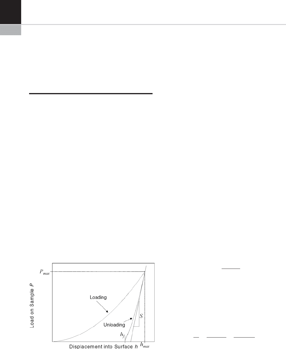
The load P and the displacement into the
surface h are continuously measured during
loading and unloading: for an overview, cf.
[8]. An example of such a load/displacement
curve is shown in Fig. 21-5. Young’s modulus
E
Indent
can be calculated from the unloading
part of the curve, as the unloading is a purely
elastic recovery process. Howe ver, the pro-
cedure is not as straigh tforwar d as for tensile
and compression tests, therefore a method to
determine E
Indent
in more detail is described.
The full procedure is presented by Oliver and
Pharr in [9].
The first step of the Oliver–Pharr data analy-
sis procedure consists of fitting the unloading
part of the load/displacement data to a power/
law r elation derived from contact mechanics
theory:
P ¼ Bðh h
f
Þ
m
ð5Þ
where P denotes the applied load, h the pene-
tration into the surface, h
f
the final displace-
ment after complete unloading (cf. Fig. 21-5)
and B and m are empirically determined fitting
parameters. From this equation, the unloading
stiffness S = dP/dh canbecalculatedbydiffer-
entiating the equation and evaluating it for
h = h
max
:
S ¼ Bmðh
max
h
f
Þ
m1
ð6Þ
Using S, the so-called contact depth h
c
can be
calculated according to:
h
c
¼ h eP=S ð7Þ
where e is a constant depending on the indenter
geometry. For three-sided pyramidal indenters
(Berkovich tips), e = 0.75. Note that the correction
for h
c
has to be used with some caution because it
is not valid in the case of material pile-up around
an indentation. Using h
c
,theprojectedcontact
area as a function of the penetration, A(h
c
)can
be calculated. With S and A, the so-called reduced
Young'smodulusE
r
can be determined:
E
r
¼
ð
ffiffiffiffiffiffiffiffi
p
_
sS
p
Þ
2b
_
sA
ð8Þ
b depends on the indenter geometry and is
equal to 1.034 for Berkovich pyramids. The
reduced Young’s modulus does not take the finite
stiffness of the tip into account. The Young’s
modulus of the sample – E
Indent
– can be extracted
from the relation:
1
E
r
¼
ð1 n
2
Þ
E
Indent
þ
ð1 n
i
2
Þ
E
i
ð9Þ
Here, n is the Poisson’s ratio of the test mate-
rial and E
i
(1141 GPa) and n
i
(0.07) are the
FIGURE 21-5 A typical load/displacement curve from an
indentation experiment.
336 CHAPTER 21 In-situ Testing of Mechanical Properties of Materials

Young’s modulus and the Poisson’sratio,
respectively, of the diamond indenter. It may
seem counter-intuitive that the Poisson’sratio
of the investigated material has to be known.
However, n is about 0.3 for most metals and
even an uncertainty of 0.1 produces an error
for E
Indent
of only about 5%. The scattering of
E
Indent
values from m easurements on the same
material with fixed measurement parameters is
within 10%.
The hardness of the material is defined by:
H ¼
P
Aðh
c
Þ
ð10Þ
The largest error source for the calculation of
hardness and Young’s modulus is the expression
used to calculate the area as a function of the
displacement. Only for an ideal (i.e. infinitely
sharp) Berkovich indenter is the relation A ¼
24:5
_
sh
2
c
valid. In reality each tip will be blunted
and may have other defects. This can be corrected
to some extent by using an area function of the
form:
Aðh
c
Þ¼a
0
_
sh
2
c
þ
X
n
i¼1
a
i
_
sh
1
2
i
:
=
c
ð11Þ
The parameters a
i
can be obtained by perform-
ing nano-indentation experiments on materi als
with a known value of Young’s modulus.
INDENTATION INSIDE THE SEM
Nano-indentation enables the measurement of
hardness and Young’s modulus of small samples
or thin coatings. However, it is not possible to
have an insight of the deformed zone of the sample
during the indentation process. As a consequence,
no information about possible crack formation or
pile-up (cf. Fig. 21-6) can be obtained. In Fig. 21-6,
an SiO
2
surface was indented by a cube-corner tip.
The information about cracking can be used to
evaluate the fracture toughness of the material.
Information about pile-up and sink-in can be used
in models of the flow, providing more accurate
data about the material. Another advantage of
in-situ indentations is the possibility to precisely
position the tip with respect to the sample surface.
This makes indentation experiments on small
structures or at specific locations possible. Finally,
there is no need to locate the indent after a test for
measuring the area of the residual imprint. For ex-
situ indentations this can be a very time consuming
task since the size of the imprints is only in the
order of nanometers. In the next paragraph issues
that have to be addressed for in-situ SEM devices
will be briefly described.
As for all in-situ m echanical tests, the SEM
environment induces several ‘design boundaries’
that do not have to be considered in a standard
indentation device working in air. It has to be
ensured that the set-up allows an unhindered
view of the indentation region. The indentation
tip axis normal to the sample surface has there-
fore to be inclined with respect to the beam axis
of the SEM. In addition the indentation tip
geometries which are normally used in indenta-
tion experiments (the four-sided Vickers pyra-
mid or t he three-sided Berkovich pyramid [10])
cannot be used because they have too large an
opening angle (140.6 degrees). For measure-
ments inside the SEM, sharper indenters such
as the c ube-corner (opening angle 84.6 degrees)
have to be used.
Figure 21-7 shows a custom-mad e instrumen-
ted indentatio n device working inside the SEM
FIGURE 21-6 In-situ indentation showing cracking and
pile-up.
CHAPTER 21 In-situ Testing of Mechanical Properties of Materials 337
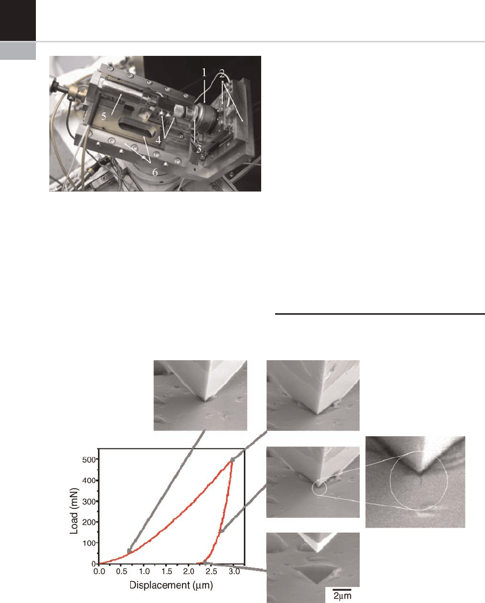
[11]. The indentation head (4) is composed of a
parallel mechanism (flexure hinges) that holds the
diamond tip. The head is drive n by a stack piezo
(5) with 20 mm range and a built-in displacement
sensor (strain gauge). The indentation head and
its actuator are assembled on a coarse positioning
stage (6) (also a flexure mechanism) and driven by
a fine-pitch pr ecision screw, remotely controlled
with a cable connected to a knob installed on the
SEM chamber’s door. The stage is fixed on the
main body by a dovetail sliding bearing. An XY
slip-stick piezo stage (2) holds the load cell (1) and
the sample (3).
As an application example, Fig. 21-8 shows the
result of an indentation experiment of a thin
nano-composite coating. Whereas the load/dis-
placement curve does not show any irregularities,
the SEM images recorded simultaneously show
the formation of pile-up and the formation of a
crack upon unloadi ng. Interestingly, the crack
almost closes completely after full unloading
and it woul d therefore be very difficult to detect
it by inspection of the residual impression only.
This demonstrates nicely the added value that can
be gained by in-situ SEM indentation experi-
ments.
IMAGE ANALYSIS
Most modern SEMs allow the recording of a
video, which can be later used to extract the
FIGURE 21-8 In-situ SEM indentation of a thin nano-compositite coating.
FIGURE 21-7 The SEM-micro-indenter: 1 load cell; 2 XY-
positioning table; 3 sample holder; 4 tip holder and adapter;
5 piezo-actuator, displacement sensor; 6 sample coarse
positioning.
338 CHAPTER 21 In-situ Testing of Mechanical Properties of Materials

displacement of different features of the sample.
Rough measurements can be done simply by
directly measuring distances with some imaging
software. However, image-analysis tools can do
this with a far greater resolution. Also, through
image-analysis algorithms it is possible to track
features throughout a whole video automatically
in order to construct, for example, a time vs strain
relationship.
There are several algorithms available for
tracking motion in an image sequence. Here, it
will be assumed that an algorithm called c ross-
correlation is employed. For a description of this
algorithm, cf. [12]. This algorithm takes a small
image and a large image as inputs. T he output
will be a map showing how similar the small
image is to each position in the larger one. By
taking the peak value the position of the smaller
image in the larger image is found. This algo-
rithm works even if there is no exact copy of the
small image within the larger. By selecting a
small feature in the first frame of the video and
trying to find this part in the following frames
gives the displacement of this particular feature.
For the c ase of compressive or tensile tests, if
two features that are close to the ends of the
sample are tracked the strain can be calculated.
This strain will be entirely independent of instru-
ment compliance. As menti oned above, strain is
not the only property that can be measured from
the images. For example, by tracking several
parts on the samples, buckling and lateral
expansion of the samples can be measured.
The cross-correlation algorithm can be
improved, making it possible to track changes
with a sub-pixel resolution , provided that the
image is well focused and that the level of noise
is low. This is important, because the total size of
an image is often about 500 pixels in width. In this
case one single pixel corresponds to 0.2% strain
assuming that the sample covers the whole image.
This low resolution would normally be consid-
ered insufficient.
When working close to the resolution limit of
an SEM, the signal is usually very weak, requiring
a very long integration time for each image. In this
case, the acquisition time for a single frame can be
several seconds. It must therefore be taken into
account also that different parts of the image are
scanned at different times, usually starting from
the top and ending at the bottom.
CASE STUDY: A COMPARISON OF
IN-SITU MICRO-TENSION AND
MICRO-COMPRESSION FOR
STUDYING THE PLASTIC
PROPERTIES OF NANO-
CRYSTALLINE ELECTRODEPOSITED
NICKEL AT DIFFERENT LENGTH
SCALES
In order to evaluate the effects of grain size or
geometrical constraints on measured mechanical
properties, there is a need to understand the influ-
ence of the measurement technique, load distribu-
tion, strain rate, etc., on the measurement values
and to correlate the measurements with deforma-
tion mechanisms. Uniaxial in-situ methods are
interesting tools for this purpose. In the following
case study a comparison of in-situ and ex-situ
micro-compression with in-situ micro-tensile tests
is shown; all the tests being used to study the
mechanical properties of electrodeposited nano-
crystalline (nc) nickel. As the material is nano-
crystalline, it would be expected that the size of
the probed volume does not influence the mechan-
ical properties as long as it is at least of the order
of a cubic micrometer. Micro-tensile tests that
probe a volume of more than 2.10
6
mm
3
show
reasonable agreement with results from micro-
compression tests that probe much smaller
volumes of down to a few mm
3
. In-situ uniaxial
solicitation in compression mode reveals several
advantages for studying stress/strain properties.
In the same way as for tensile meas urements, a
quantitative evaluation of the deformation during
compression through video frame records [13]
was found possible.
The material investigated was electrodeposited
nano-crystalline (nc) nickel. Figure 21-9 shows an
HRSEM picture of the nc Ni surface. The sizes of
the grains vary between 30 and 200 nm with an
average of 50 nm. The inset in Fig. 21-9 displays a
TEM cross-section of the film. The grains have a
CHAPTER 21 In-situ Testing of Mechanical Properties of Materials 339
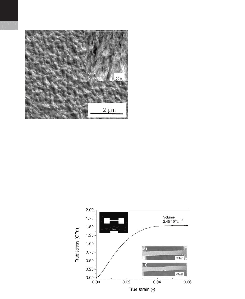
predominantly columnar structure parallel to the
deposition direction.
The samples for tensile testing w ere manu-
factured by a LIGA process. The 10 mm pillars
for in-situ compression w ere also manufac-
tured by LIGA, whereas the 2 m m pillars for
ex-situ compressi on were produced by FIB
machining.
The in-situ tensile tests were carried out
at a constant strain rate of 0.2 10
3
s
1
.
Figure 21-10 shows the average true stress/strain
(s/e) curve (i.e. measurements made prior to neck-
ing) obtained from micro-tensile measurements.
The curve indicates weak strain hardening leading
to an increase of the required stress for further
deformation of the tested specimen. Figure
21-10(a) shows an SEM image of the dog-bone
central section extracted from the video frames
recorded at the beginning of a measurement and
Fig. 21.10(b) represents SEM video frame of the
micro-tensile bars just before fracture, revealing
necking in the central part. An inset on the left
part of the graph shows an optical picture of the
typical dog-bone used.
The in-situ compressive tests were carried out
using a flat diamond punch of 15 mm diameter.
The strain rate was 0.2 10
3
s
1
. Figure 21-11
displays true s/e curves obtai ned on 10 microme-
ter diameter pillars (aspect ratio 3:1) with in-situ
compressive tests. Figure 21-11(a) and (b) for the
10 micrometer diameter pillar tested represent
the video frames extracted at the beginning and
at the end of a typical in-situ compressive test,
FIGURE 21-10 Average tensile stress/strain curves obtained from four samples. The inset of the left part of the graph shows
an optical picture of the typical dog-bone specimen tested.
FIGURE 21-9 HRSEM image of the nc Ni surface; rough-
ness and grain size are easily identified on this picture. The
inset of the right of the picture shows a TEM bright-field
image of the specimen indicating the growth direction of
the electrodeposition.
340 CHAPTER 21 In-situ Testing of Mechanical Properties of Materials