Pumping Station Desing - Second Edition by Robert L. Sanks, George Tchobahoglous, Garr M. Jones
Подождите немного. Документ загружается.

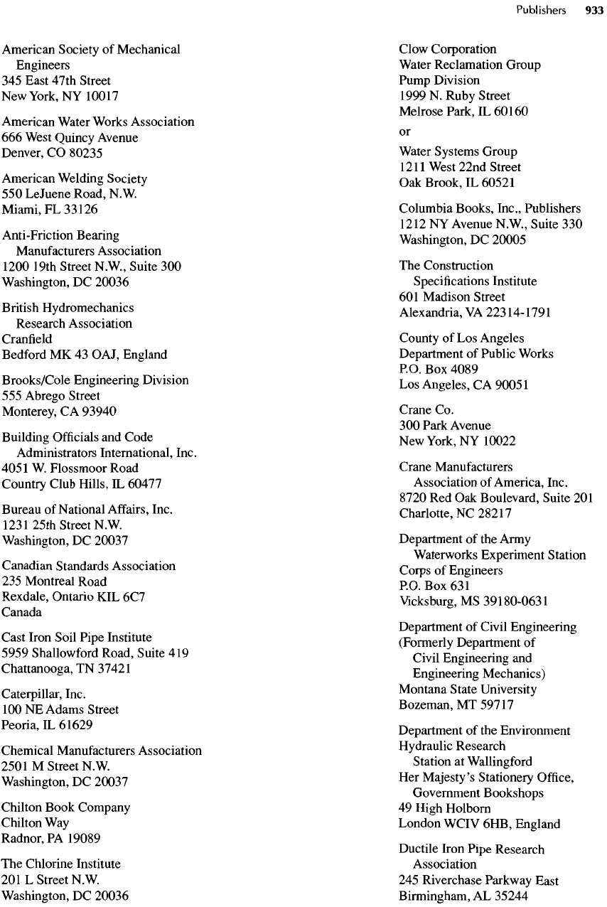
American Society
of
Mechanical
Engineers
345
East 47th Street
New
York,
NY
10017
American Water Works Association
666
West Quincy Avenue
Denver,
CO
80235
American Welding Society
550
LeJuene Road,
N.
W
Miami,
FL
33
126
Anti-Friction Bearing
Manufacturers
Association
1200 19th Street N.W., Suite
300
Washington,
DC
20036
British Hydromechanics
Research Association
Cranfield
Bedford
MK 43
OAJ, England
Brooks/Cole Engineering Division
555
Abrego Street
Monterey,
CA
93940
Building
Officials
and
Code
Administrators International, Inc.
4051
W.
Flossmoor Road
Country
Club Hills,
IL
60477
Bureau
of
National
Affairs,
Inc.
123
125th
Street
N.
W.
Washington,
DC
20037
Canadian
Standards Association
235
Montreal Road
Rexdale, Ontario
KIL 6C7
Canada
Cast Iron Soil Pipe Institute
5959
Shallowford
Road, Suite
419
Chattanooga,
TN
37421
Caterpillar, Inc.
100
NE
Adams Street
Peoria,IL61629
Chemical
Manufacturers Association
250
IM
Street
N.
W.
Washington,
DC
20037
Chilton Book Company
Chilton
Way
Radnor,
PA
19089
The
Chlorine Institute
201 L
Street N.W.
Washington,
DC
20036
Clow
Corporation
Water
Reclamation Group
Pump Division
1999
N.
Ruby Street
Melrose Park,
IL
60160
or
Water
Systems Group
121
!West
22nd Street
Oak
Brook,
IL
60521
Columbia Books, Inc., Publishers
1212
NY
Avenue N.W, Suite
330
Washington,
DC
20005
The
Construction
Specifications
Institute
601
Madison Street
Alexandria,
VA
22314-1791
County
of Los
Angeles
Department
of
Public Works
P.O.
Box
4089
Los
Angeles,
CA
90051
Crane
Co.
300
Park Avenue
New
York,
NY
10022
Crane Manufacturers
Association
of
America, Inc.
8720
Red Oak
Boulevard, Suite
201
Charlotte,
NC
28217
Department
of the
Army
Waterworks Experiment Station
Corps
of
Engineers
P.O.
Box
631
Vicksburg,
MS
39180-0631
Department
of
Civil Engineering
(Formerly Department
of
Civil
Engineering
and
Engineering Mechanics)
Montana State University
Bozeman,MT59717
Department
of the
Environment
Hydraulic Research
Station
at
Wallingford
Her
Majesty's Stationery
Office,
Government Bookshops
49
High
Holborn
London WCIV
6HB,
England
Ductile Iron
Pipe
Research
Association
245
Riverchase Parkway East
Birmingham,
AL
35244
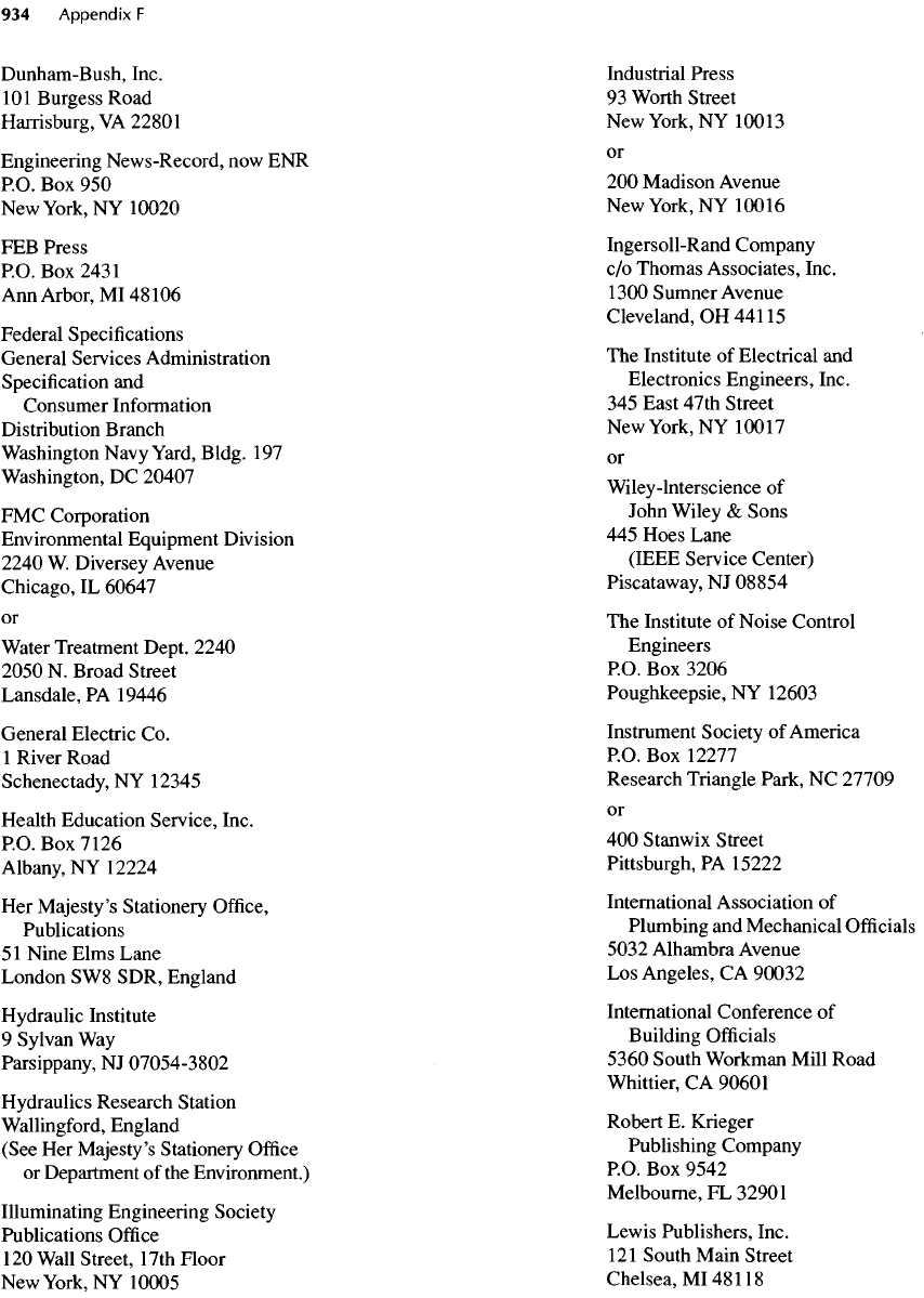
Dunham-Bush,
Inc.
101
Burgess Road
Harrisburg,
VA
22801
Engineering News-Record,
now ENR
RO.
Box 950
New
York,
NY
10020
FEB
Press
RO.
Box
2431
Ann
Arbor,
MI
48
106
Federal Specifications
General Services Administration
Specification
and
Consumer Information
Distribution Branch
Washington
Navy Yard,
Bldg.
197
Washington,
DC
20407
FMC
Corporation
Environmental Equipment Division
2240
W.
Diversey Avenue
Chicago,
IL
60647
or
Water
Treatment Dept. 2240
2050
N.
Broad Street
Lansdale,
PA
19446
General Electric
Co.
1
River Road
Schenectady,
NY
12345
Health Education Service, Inc.
P.O.
Box
7
126
Albany,
NY
12224
Her
Majesty's Stationery
Office,
Publications
5
1
Nine Elms Lane
London
SW8
SDR, England
Hydraulic Institute
9
Sylvan
Way
Parsippany,
NJ
07054-3802
Hydraulics Research Station
Wallingford,
England
(See
Her
Majesty's Stationery
Office
or
Department
of the
Environment.)
Illuminating Engineering Society
Publications
Office
120
Wall Street, 17th Floor
New
York,
NY
10005
Industrial Press
93
Worth Street
New
York,
NY
10013
or
200
Madison Avenue
New
York,
NY
10016
Ingersoll-Rand
Company
c/o
Thomas Associates, Inc.
1
300
Sumner Avenue
Cleveland,
OH
441
15
The
Institute
of
Electrical
and
Electronics Engineers, Inc.
345
East 47th Street
New
York,
NY
10017
or
Wiley-lnterscience
of
John Wiley
&
Sons
445
Hoes Lane
(IEEE Service Center)
Piscataway,
NJ
08854
The
Institute
of
Noise Control
Engineers
P.O.
Box
3206
Poughkeepsie,
NY
12603
Instrument Society
of
America
P.O.
Box
12277
Research Triangle Park,
NC
27709
or
400
Stanwix Street
Pittsburgh,
PA
15222
International Association
of
Plumbing
and
Mechanical
Officials
5032 Alhambra Avenue
Los
Angeles,
CA
90032
International Conference
of
Building
Officials
5360
South Workman Mill Road
Whittier,
CA
90601
Robert
E.
Krieger
Publishing Company
P.O.
Box
9542
Melbourne,
FL
32901
Lewis Publishers, Inc.
121
South Main Street
Chelsea,
MI
481
18
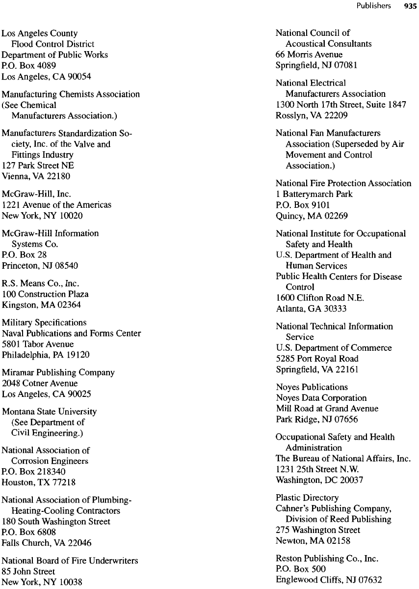
Los
Angeles County
Flood Control District
Department
of
Public Works
P.O.
Box
4089
Los
Angeles,
CA
90054
Manufacturing
Chemists Association
(See Chemical
Manufacturers
Association.)
Manufacturers
Standardization
So-
ciety,
Inc.
of the
Valve
and
Fittings Industry
127
Park Street
NE
Vienna,
VA
22
180
McGraw-Hill,
Inc.
1221
Avenue
of the
Americas
New
York,
NY
10020
McGraw-Hill
Information
Systems
Co.
P.O.
Box 28
Princeton,
NJ
08540
R.S. Means Co., Inc.
100
Construction Plaza
Kingston,
MA
02364
Military
Specifications
Naval
Publications
and
Forms Center
5801 Tabor Avenue
Philadelphia,
PA
19120
Miramar
Publishing Company
2048 Cotner Avenue
Los
Angeles,
CA
90025
Montana
State University
(See Department
of
Civil Engineering.)
National
Association
of
Corrosion Engineers
P.O.
Box
2
18340
Houston,
TX
772
18
National
Association
of
Plumbing-
Heating-Cooling Contractors
180
South Washington Street
P.O.
Box
6808
Falls Church,
VA
22046
National
Board
of
Fire Underwriters
85
John Street
New
York,
NY
10038
National Council
of
Acoustical Consultants
66
Morris Avenue
Springfield,
NJ
07081
National
Electrical
Manufacturers
Association
1300
North 17th Street, Suite
1847
Rosslyn,
VA
22209
National
Fan
Manufacturers
Association (Superseded
by Air
Movement
and
Control
Association.)
National
Fire Protection Association
1
Batterymarch Park
P.O.
Box
9101
Quincy,
MA
02269
National
Institute
for
Occupational
Safety
and
Health
U.S.
Department
of
Health
and
Human
Services
Public Health Centers
for
Disease
Control
1600
Clifton Road N.E.
Atlanta,
GA
30333
National Technical Information
Service
U.S. Department
of
Commerce
5285 Port Royal Road
Springfield,
VA
22
161
Noyes
Publications
Noyes Data Corporation
Mill
Road
at
Grand Avenue
Park Ridge,
NJ
07656
Occupational Safety
and
Health
Administration
The
Bureau
of
National
Affairs,
Inc.
123
125th
Street
N.
W.
Washington,
DC
20037
Plastic Directory
Cahner's
Publishing Company,
Division
of
Reed Publishing
275
Washington Street
Newton,
MA
02158
Reston
Publishing Co., Inc.
P.O.
Box 500
Englewood
Cliffs,
NJ
07632
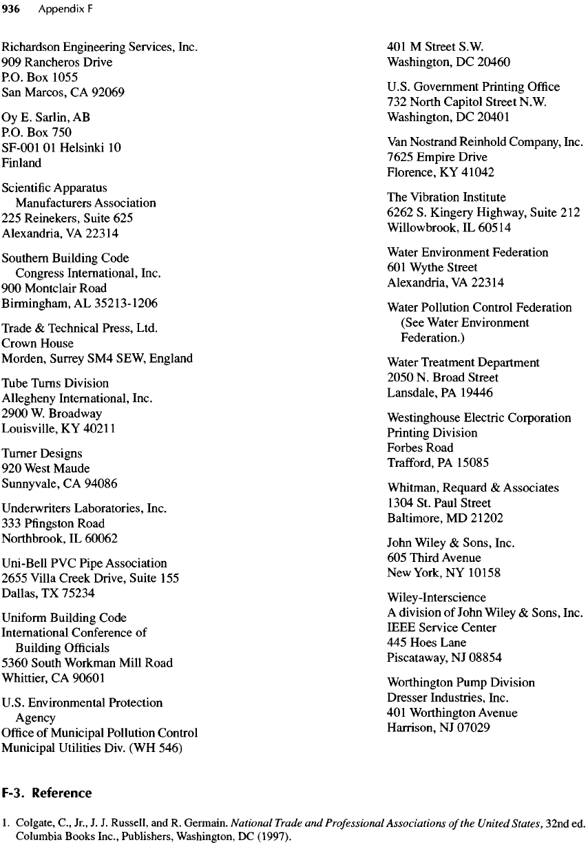
Richardson Engineering Services, Inc.
909
Rancheros Drive
P.O.
Box
1055
San
Marcos,
CA
92069
Oy
E.
Sarlin,
AB
P.O.
Box 750
SF-OOl
Ol
Helsinki
10
Finland
Scientific
Apparatus
Manufacturers
Association
225
Reinekers, Suite
625
Alexandria,
VA
223
14
Southern
Building Code
Congress International, Inc.
900
Montclair Road
Birmingham,
AL
35213-1206
Trade
&
Technical Press, Ltd.
Crown
House
Morden, Surrey
SM4
SEW, England
Tube Turns Division
Allegheny
International, Inc.
2900
W.
Broadway
Louisville,
KY
402
11
Turner Designs
920
West Maude
Sunnyvale,
CA
94086
Underwriters Laboratories, Inc.
333
Pfingston
Road
Northbrook,
IL
60062
Uni-Bell
PVC
Pipe Association
2655 Villa Creek Drive, Suite
155
Dallas,
TX
75234
Uniform
Building Code
International Conference
of
Building
Officials
5360
South Workman Mill Road
Whittier,
CA
90601
U.S. Environmental Protection
Agency
Office
of
Municipal Pollution Control
Municipal
Utilities Div.
(WH
546)
401 M
Street S.W.
Washington,
DC
20460
U.S. Government Printing
Office
732
North Capitol Street N.W.
Washington,
DC
20401
Van
Nostrand
Reinhold
Company, Inc.
7625
Empire Drive
Florence,
KY
41042
The
Vibration Institute
6262
S.
Kingery
Highway, Suite
212
Willowbrook,IL60514
Water
Environment Federation
601
Wythe Street
Alexandria,
VA
223
14
Water Pollution Control Federation
(See Water Environment
Federation.)
Water Treatment Department
2050
N.
Broad Street
Lansdale,
PA
19446
Westinghouse Electric Corporation
Printing Division
Forbes Road
Trafford,
PA
15085
Whitman, Requard
&
Associates
1304
St.
Paul Street
Baltimore,
MD
21202
John Wiley
&
Sons, Inc.
605
Third Avenue
New
York,
NY
10158
Wiley-Interscience
A
division
of
John Wiley
&
Sons, Inc.
IEEE Service Center
445
Hoes Lane
Piscataway,
NJ
08854
Worthington
Pump Division
Dresser Industries, Inc.
401
Worthington Avenue
Harrison,
NJ
07029
F-3. Reference
1.
Colgate,
C.,
Jr.,
J. J.
Russell,
and R.
Germain.
National
Trade
and
Professional
Associations
of
the
United
States, 32nd
ed.
Columbia
Books Inc., Publishers, Washington,
DC
(1997).
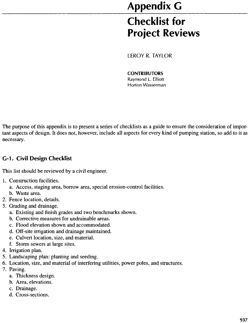
Appendix
G
Checklist
for
Project
Reviews
LEROY
R.
TAYLOR
CONTRIBUTORS
Raymond
L.
Elliott
Morton
Wasserman
The
purpose
of
this appendix
is to
present
a
series
of
checklists
as a
guide
to
ensure
the
consideration
of
impor-
tant
aspects
of
design.
It
does not, however, include
all
aspects
for
every kind
of
pumping station,
so add to it as
necessary.
G-1.
Civil Design Checklist
This list should
be
reviewed
by a
civil engineer.
1.
Construction facilities.
a.
Access, staging area, borrow area, special erosion-control facilities.
b.
Waste area.
2.
Fence location, details.
3.
Grading
and
drainage.
a.
Existing
and finish
grades
and two
benchmarks shown.
b.
Corrective measures
for
undrainable areas.
c.
Flood elevation shown
and
accommodated.
d.
Off-site
irrigation
and
drainage maintained.
e.
Culvert location, size,
and
material.
f.
Storm sewers
at
large sites.
4.
Irrigation plan.
5.
Landscaping plan: planting
and
seeding.
6.
Location, size,
and
material
of
interfering utilities, power poles,
and
structures.
7.
Paving.
a.
Thickness design.
b.
Area, elevations.
c.
Drainage.
d.
Cross-sections.
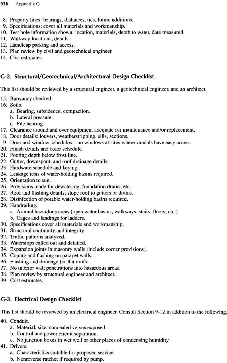
8.
Property lines: bearings, distances, ties,
future
additions.
9.
Specifications: cover
all
materials
and
workmanship.
10.
Test hole information shown: location, materials, depth
to
water, date measured.
11.
Walkway locations, details.
12.
Handicap parking
and
access.
13.
Plan review
by
civil
and
geotechnical engineer.
14.
Cost estimates.
G-2.
Structural/Geotechnical/Architectural
Design
Checklist
This list should
be
reviewed
by a
structural engineer,
a
geotechnical engineer,
and an
architect.
15.
Buoyancy checked.
16.
Soils.
a.
Bearing, subsidence, compaction.
b.
Lateral pressure.
c.
Pile bearing.
17.
Clearance around
and
over equipment adequate
for
maintenance and/or replacement.
18.
Door details: louvers, weatherstripping, sills, sections.
19.
Door
and
window
schedules—no
windows
at
sites where vandals have easy access.
20.
Finish details
and
color schedule.
21.
Footing depth below
frost
line.
22.
Gutter, downspout,
and
roof drainage details.
23.
Hardware schedule
and
keying.
24.
Leakage tests
of
water-holding basins required.
25.
Orientation
to
sun.
26.
Provisions made
for
dewatering, foundation drains, etc.
27.
Roof
and
flashing
details; slope roof
to
gutters
or
drains.
28.
Disinfection
of
potable water-holding basins required.
29.
Handrailing.
a.
Around hazardous areas (open water basins, walkways, stairs,
floors,
etc.).
b.
Cages
and
landings
for
ladders.
30.
Specifications cover
all
materials
and
workmanship.
31.
Structural continuity
and
integrity.
32.
Traffic
patterns analyzed.
33.
Waterstops called
out and
detailed.
34.
Expansion joints
in
masonry walls (include corner provisions).
35.
Coping
and flashing on
parapet walls.
36.
Flashing
and
drainage
for flat
roofs.
37.
No
interior wall penetrations into hazardous areas.
38.
Plan review
by
structural engineer
and
architect.
39.
Cost estimates.
G-3.
Electrical
Design
Checklist
This list should
be
reviewed
by an
electrical engineer. Consult Section
9-12
in
addition
to the
following.
40.
Conduit.
a.
Material, size, concealed versus exposed.
b.
Control
and
power circuit separation.
c. No
junction boxes
in wet
well
or
other places
of
condensing humidity.
41.
Drivers.
a.
Characteristics suitable
for
proposed service.
b.
Nonreverse
ratchet
if
required
by
pump.
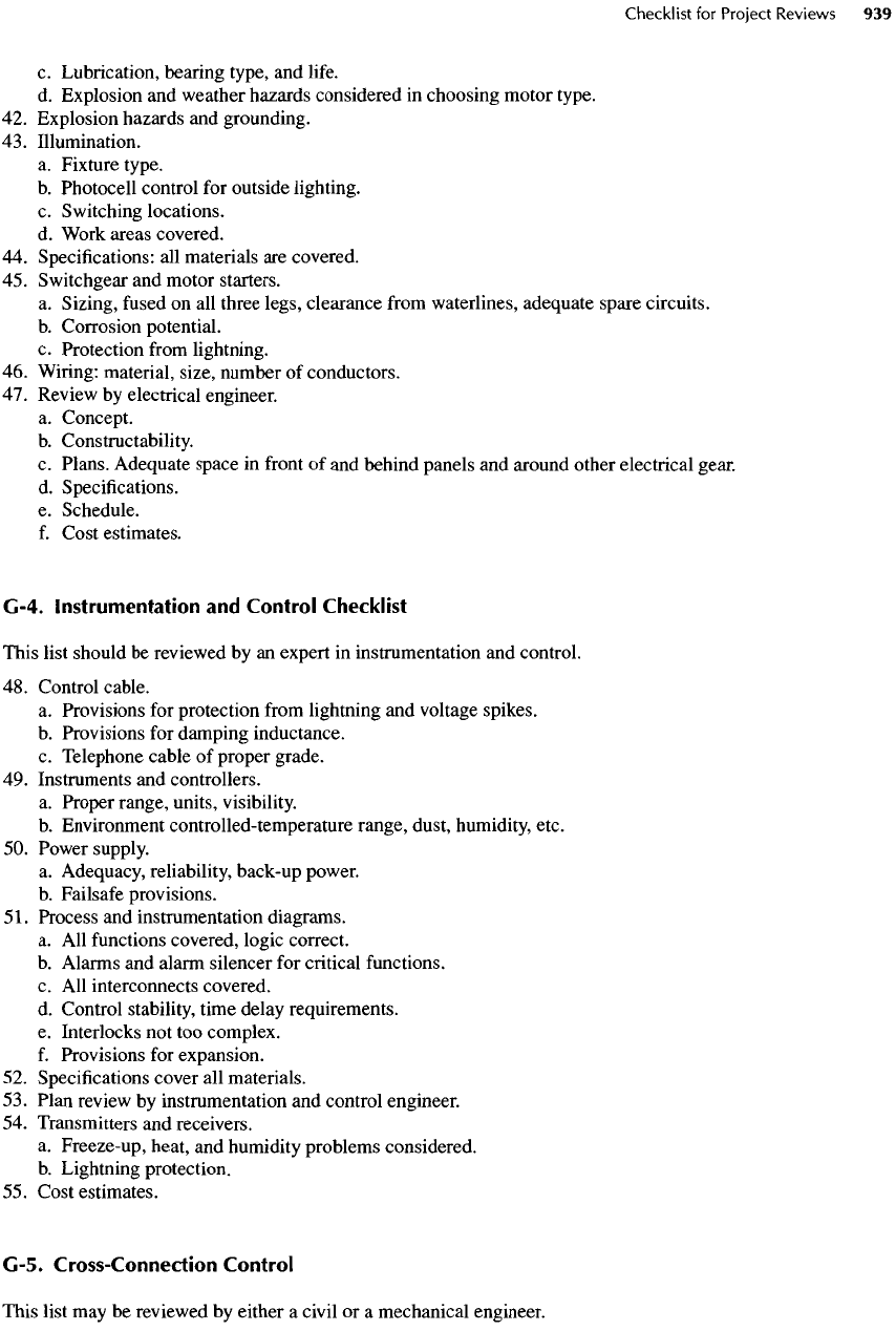
c.
Lubrication, bearing type,
and
life.
d.
Explosion
and
weather hazards considered
in
choosing motor type.
42.
Explosion hazards
and
grounding.
43.
Illumination.
a.
Fixture type.
b.
Photocell control
for
outside lighting.
c.
Switching locations.
d.
Work areas covered.
44.
Specifications:
all
materials
are
covered.
45.
Switchgear
and
motor starters.
a.
Sizing,
fused
on all
three legs, clearance
from
waterlines, adequate spare
circuits.
b.
Corrosion potential.
c.
Protection
from
lightning.
46.
Wiring: material, size, number
of
conductors.
47.
Review
by
electrical engineer.
a.
Concept.
b.
Constructability.
c.
Plans. Adequate space
in
front
of and
behind panels
and
around other electrical gear.
d.
Specifications.
e.
Schedule.
f.
Cost estimates.
G-4. Instrumentation
and
Control Checklist
This list should
be
reviewed
by an
expert
in
instrumentation
and
control.
48.
Control cable.
a.
Provisions
for
protection
from
lightning
and
voltage spikes.
b.
Provisions
for
damping inductance.
c.
Telephone cable
of
proper grade.
49.
Instruments
and
controllers.
a.
Proper range, units, visibility.
b.
Environment controlled-temperature range, dust, humidity, etc.
50.
Power supply.
a.
Adequacy, reliability, back-up power.
b.
Failsafe provisions.
51.
Process
and
instrumentation diagrams.
a.
All
functions
covered, logic correct.
b.
Alarms
and
alarm silencer
for
critical
functions.
c.
All
interconnects covered.
d.
Control stability, time delay requirements.
e.
Interlocks
not too
complex.
f.
Provisions
for
expansion.
52.
Specifications cover
all
materials.
53.
Plan review
by
instrumentation
and
control engineer.
54.
Transmitters
and
receivers.
a.
Freeze-up, heat,
and
humidity problems considered.
b.
Lightning protection.
55.
Cost estimates.
G-5. Cross-Connection Control
This
list
may be
reviewed
by
either
a
civil
or a
mechanical engineer.
Water
Plants
56.
Cross-connections
in
water plants
can
result
in
contamination
of
potable water supplies
by
untreated
or
par-
tially
treated water, chemicals, sanitary wastes, drainage water,
and
similar hazardous sources. During
design reviews,
a
checklist should
be
used
to
spot hazards. Include
the
following:
a.
Inadvertent pipe connections between systems eliminated.
b.
Avoid potential cross-connections
due to
hoses.
c.
Back siphonage hazards eliminated.
d.
Backflow
prevention
for
underground sprinkler systems, pump water seal systems, cooling water sys-
tems,
etc.; provide
air gap on a
receiving tank,
if
possible.
e.
Water
and
sewer line crossings meet state standards.
f.
Positive intake pressure
is
maintained
on
booster pumps.
g.
Pump suction lines
are not
buried
(or at
least negative pressure
is
prevented); burial
is
satisfactory
for
raw
water before treatment.
h.
Backflow
preventers
in floodproof
location (above
flood
elevation).
i.
Operation
and
maintenance instructions include cross-connection-control program.
Wastewater
Plants
57.
Cross-connection hazards
in
wastewater plants
are
similar
to
those
in a
water plant,
but
sanitary hazards
are
much
more dangerous.
A
backflow
preventer should
be
installed
on the
main water supply
line
to the
plant
and
an air gap
should
be
provided
on
hose bibbs where
the
hose
may
inadvertently
be
left
in a
tank
or
other
sanitary
or
chemical hazard. Extra vigilance must
be
used
to
spot actual pipe cross-connections during both
design
and
construction. Because there
are
often
a
number
of
grades
of
water (such
as
potable
and
plant
effluent),
pipe-marking systems
are
especially important. Keep
backflow
preventers above
flood
level
and
vent
to the
outside
of the
building. Angele
[1] and
AWWA
M-14
[2]
give more complete discussions.
G-6. Mechanical Design Checklist
This
list should
be
reviewed
in
general
by a
civil
or
mechanical engineer. Parts
of it
require specialists
in
heating
and
ventilating, engines, pumps, control
and
instrumentation, water hammer analysis,
and
hydraulics.
58.
Auxiliary power.
a. Air
cooling systems adequate.
b.
Alarm systems
for
critical
functions.
c.
Automatic start system
and
timer
for
critical systems, marked
to
indicate hazard
of
automatic starting.
d.
Coupling
on
shaft
shielded
for
safety.
e.
Engine horsepower adequate
for
start-up
and
continuous duty
after
derating
for
elevation.
f.
Exhaust system meets requirements
for
neighborhood noise levels,
is
insulated
from
flammable
materi-
als,
and is
installed above snow level.
g.
Fuel systems
and
capacity.
h.
Water cooling systems protected against freeze-up
and
separated
by air gap
from
potable water systems.
i.
Heat recovery feasibility.
j.
Chlorine gas: design
feed
rates.
59.
Drivers—see
Electrical Design Checklist.
60.
Flowmeter.
a.
Clearance
from
obstructions
and flow
disturbances (adequate length
of
straight pipe
on
both ends).
b.
Sizing
and
proper units
for
readout.
c.
Volumetric accuracy. Calibrate
in
situ
for
guaranteed accuracy.
d.
Bypass
for
removal
or
cleaning.
61.
Heating, ventilating,
and air
conditioning.
a. Air
inlet, exhaust,
and fan
adequate
for
motor cooling.
b.
Floor level exhaust
for
chlorine room with outside switch
and
high level
air
inlet.
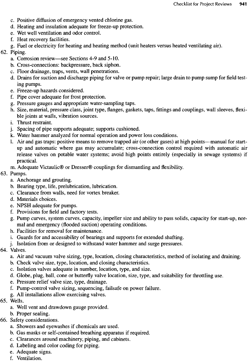
c.
Positive
diffusion
of
emergency vented chlorine gas.
d.
Heating
and
insulation adequate
for
freeze-up
protection.
e. Wet
well ventilation
and
odor control.
f.
Heat recovery facilities.
g.
Fuel
or
electricity
for
heating
and
heating method (unit heaters versus heated ventilating air).
62.
Piping.
a.
Corrosion
review—see
Sections
4-9 and
5-10.
b.
Cross-connections: backpressure, back siphon.
c.
Floor
drainage, traps, vents, wall penetrations.
d.
Drains
for
suction
and
discharge piping
for
valve
or
pump repair; large drain
to
pump sump
for field
test-
ing
pumps.
e.
Freeze-up hazards considered.
f.
Pipe
cover adequate
for
frost
protection.
g.
Pressure gauges
and
appropriate water-sampling taps.
h.
Size, material, pressure class, joint type,
flanges,
gaskets, taps,
fittings and
couplings, wall sleeves,
flexi-
ble
joints
at
walls, vibration sources.
i.
Thrust restraint.
j.
Spacing
of
pipe supports adequate; supports cushioned.
k.
Water hammer analyzed
for
normal operation
and
power loss conditions.
1.
Air and gas
traps: positive means
to
remove trapped
air (or
other gases)
at
high
points—manual
for
start-
up
and
automatic where
gas may
accumulate; cross-connection control required
with
automatic
air
release
valves
on
potable water systems; avoid high
points
entirely (especially
in
sewage systems)
if
practical.
m.
Adequate Victaulic®
or
Dresser® couplings
for
dismantling
and flexibility.
63.
Pumps.
a.
Anchorage
and
grouting.
b.
Bearing type,
life,
prelubrication,
lubrication.
c.
Clearance
from
walls, need
for
vortex breaker.
d.
Materials choices.
e.
NPSH adequate
for
pumps.
f.
Provisions
for field and
factory
tests.
g.
Pump curves, system curves, capacity, impeller size
and
ability
to
pass solids, capacity
for
start-up, nor-
mal
and
emergency
(flooded
suction) operating conditions.
h.
Facilities
for
removal
for
maintenance.
i.
Guards
for and
accessibility
of
bearings
and
supports
for
extended
shafting.
j.
Isolation
from
or
designed
to
withstand water hammer
and
surge pressures.
64.
Valves.
a. Air and
vacuum
valve sizing, type, location, closing characteristics, method
of
isolating
and
draining.
b.
Check valve size, type, location,
and
closing characteristics.
c.
Isolation valves adequate
in
number, location, type,
and
size.
d.
Globe, plug, ball, cone
or
butterfly
valve location, size, type,
and
suitability
for
throttling use.
e.
Pressure relief valve size, type, drainage.
f.
Pump-control valve sizing, sequencing,
failsafe
on
power
failure.
g.
All
installations allow exercising valves.
65.
Wells.
a.
Well vent
and
drawdown gauge provided.
b.
Proper sealing.
66.
Safety
considerations.
a.
Showers
and
eyewashes
if
chemicals
are
used.
b.
Gas
masks
or
self-contained breathing apparatus
if
required.
c.
Clearances around machinery, piping,
and
cabinets.
d.
Labeling
and
color coding
for
piping.
e.
Adequate signs.
f.
Ventilation.
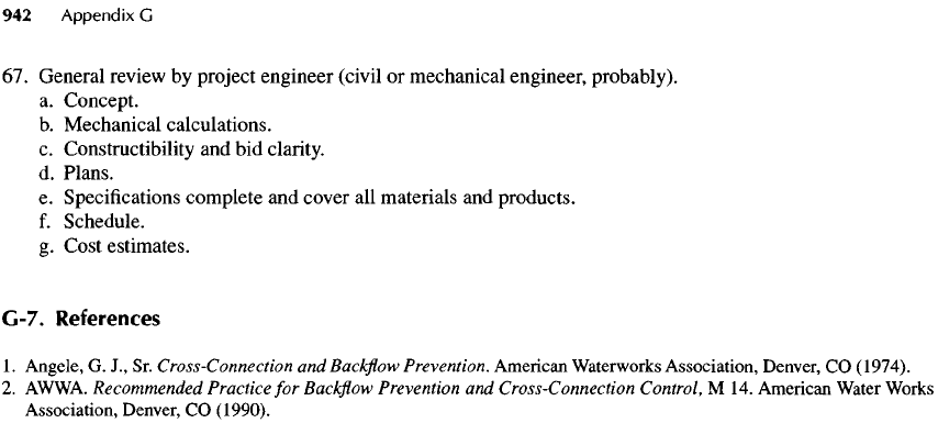
67.
General review
by
project engineer (civil
or
mechanical engineer, probably).
a.
Concept.
b.
Mechanical calculations.
c.
Constructibility
and bid
clarity.
d.
Plans.
e.
Specifications complete
and
cover
all
materials
and
products.
f.
Schedule.
g.
Cost estimates.
G-7.
References
1.
Angele,
G.
J.,
Sr.
Cross-Connection
andBackflow
Prevention. American Waterworks Association, Denver,
CO
(1974).
2.
AWWA.
Recommended
Practice
for
Backflow
Prevention
and
Cross-Connection
Control,
M 14.
American Water Works
Association,
Denver,
CO
(1990).
