Pumping Station Desing - Second Edition by Robert L. Sanks, George Tchobahoglous, Garr M. Jones
Подождите немного. Документ загружается.

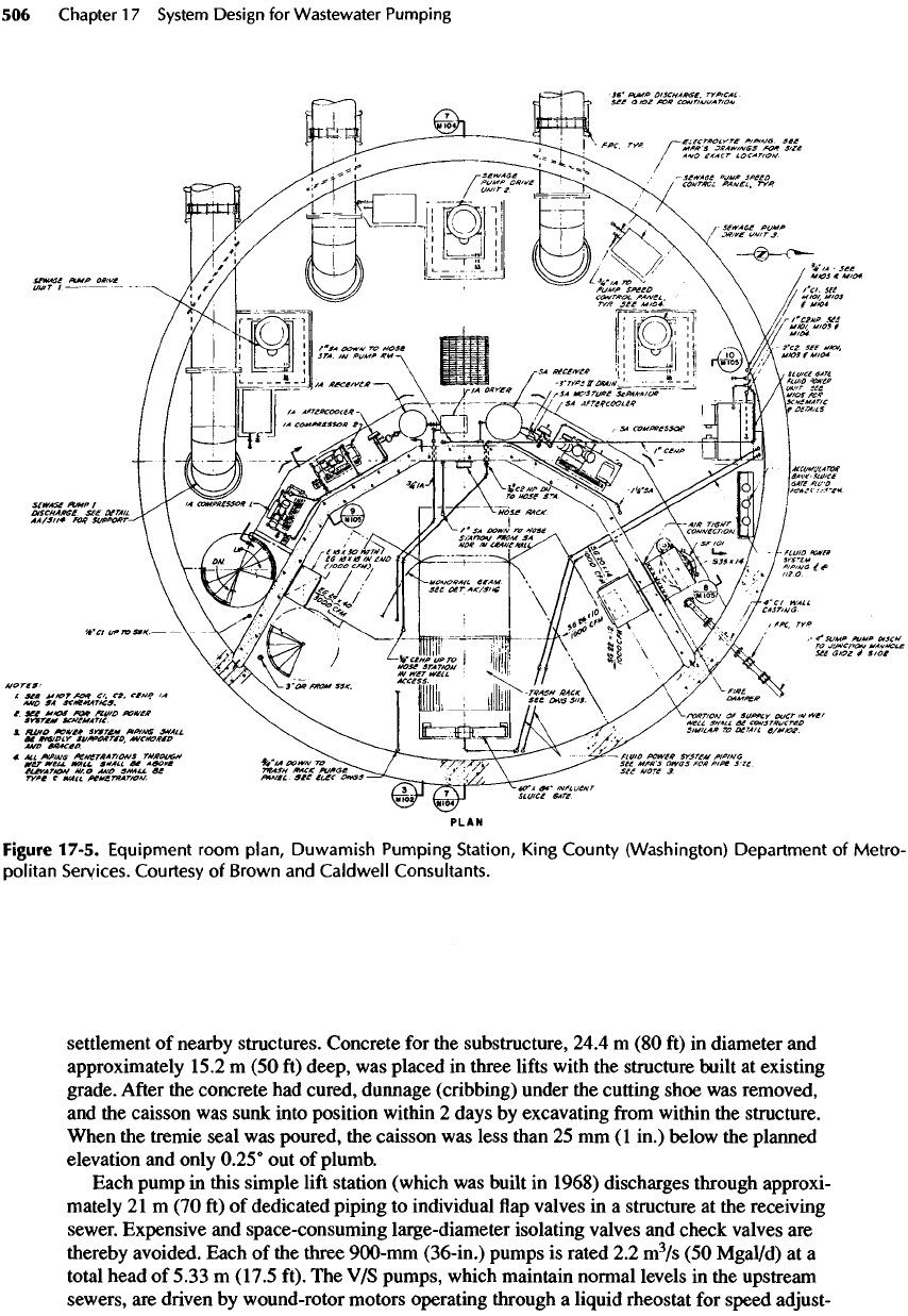
Figure
17-5.
Equipment room
plan,
Duwamish Pumping Station, King County (Washington) Department
of
Metro-
politan
Services.
Courtesy
of
Brown
and
Caldwell Consultants.
settlement
of
nearby structures. Concrete
for the
substructure,
24.4
m (80 ft) in
diameter
and
approximately
15.2
m (50 ft)
deep,
was
placed
in
three
lifts
with
the
structure built
at
existing
grade.
After
the
concrete
had
cured, dunnage (cribbing) under
the
cutting shoe
was
removed,
and
the
caisson
was
sunk into
position
within
2
days
by
excavating
from
within
the
structure.
When
the
tremie seal
was
poured,
the
caisson
was
less
than
25 mm (1
in.)
below
the
planned
elevation
and
only 0.25°
out of
plumb.
Each pump
in
this simple
lift
station (which
was
built
in
1968)
discharges through approxi-
mately
21m
(70 ft) of
dedicated piping
to
individual
flap
valves
in a
structure
at the
receiving
sewer. Expensive
and
space-consuming large-diameter isolating valves
and
check valves
are
thereby avoided. Each
of the
three
900-mm
(36-in.)
pumps
is
rated
2.2
m
3
/s
(50
Mgal/d)
at a
total head
of
5.33
m
(17.5
ft).
The V/S
pumps, which maintain normal levels
in the
upstream
sewers,
are
driven
by
wound-rotor motors operating through
a
liquid rheostat
for
speed
adjust-
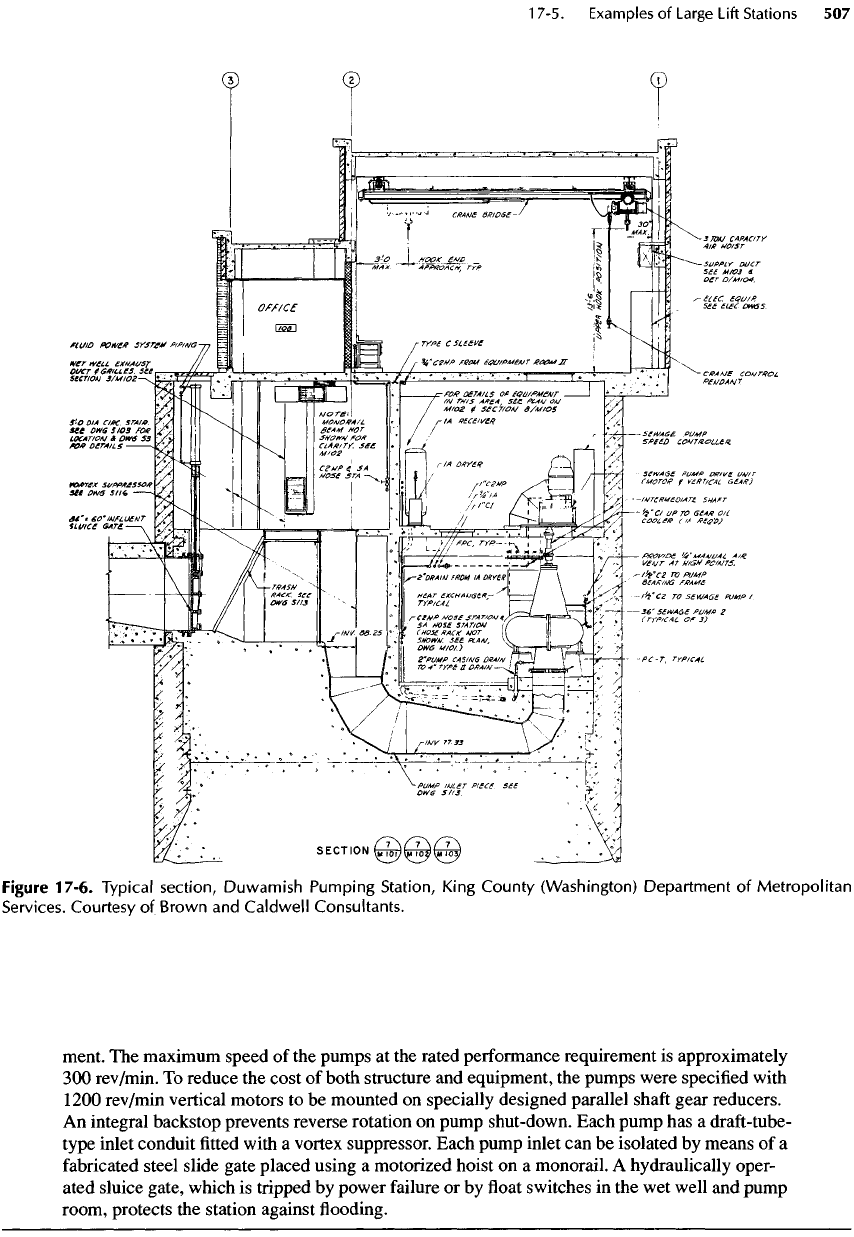
Figure
17-6.
Typical
section,
Duwamish
Pumping
Station,
King
County
(Washington)
Department
of
Metropolitan
Services.
Courtesy
of
Brown
and
Caldwell
Consultants.
ment.
The
maximum speed
of the
pumps
at the
rated performance requirement
is
approximately
300
rev/min.
To
reduce
the
cost
of
both structure
and
equipment,
the
pumps were specified with
1200
rev/min vertical motors
to be
mounted
on
specially designed parallel
shaft
gear reducers.
An
integral backstop prevents reverse rotation
on
pump shut-down. Each pump
has a
draft-tube-
type inlet conduit
fitted
with
a
vortex suppressor. Each pump inlet
can be
isolated
by
means
of a
fabricated
steel slide gate placed using
a
motorized hoist
on a
monorail.
A
hydraulically oper-
ated sluice gate, which
is
tripped
by
power failure
or by float
switches
in the wet
well
and
pump
room, protects
the
station against
flooding.
Example
17-2
lnterbay Pumping Station
The
lnterbay Pumping Station (shown
in
Figures 17-7 through 17-9)
was
constructed
in
1966
on
a
site
in an
ancient saltwater embayment.
The
underlying soils were quite
soft,
and the
ground-
water
table reflected
fluctuations in
tidal level
in an
adjacent harbor.
The
site
was
very con-
strained, with important structures (some
of
them quite fragile) nearby. Because soils
at the
base
of
the
structure lacked
sufficient
supporting strength, piles were
favored
over
a
caisson.
The
construction procedure
was to
(1)
drive
a
sheet pile
cofferdam,
(2)
excavate
the
site,
(3)
drive
the
pile
foundation with
the
cofferdam
flooded, (4)
pour
a
tremie seal
at an
elevation below
the
planned foundation slab,
(5)
dewater
the
cofferdam
after
the
tremie concrete
had
cured,
(6) cut
off
the
piles,
and (7)
construct
the
foundation slab. General
dewatering
at the
site, which would
have
compressed
the
local
soft
soils
and
severely damaged many nearby structures
and
surface
improvements,
was
thereby avoided.
Each
of the
three
900-mm
(36-in.)
pumps
is
rated
to
deliver
2.6
m
3
/s
(60
Mgal/d)
against
12
m
(39 ft) of
total head
at a
maximum pump speed
of 360
rev/min.
The
engines
are
rated
for 370
kW
(500
hp) at 820
rev/min.
The
twin
1200-mm
(48-in.) force mains
are
each approximately
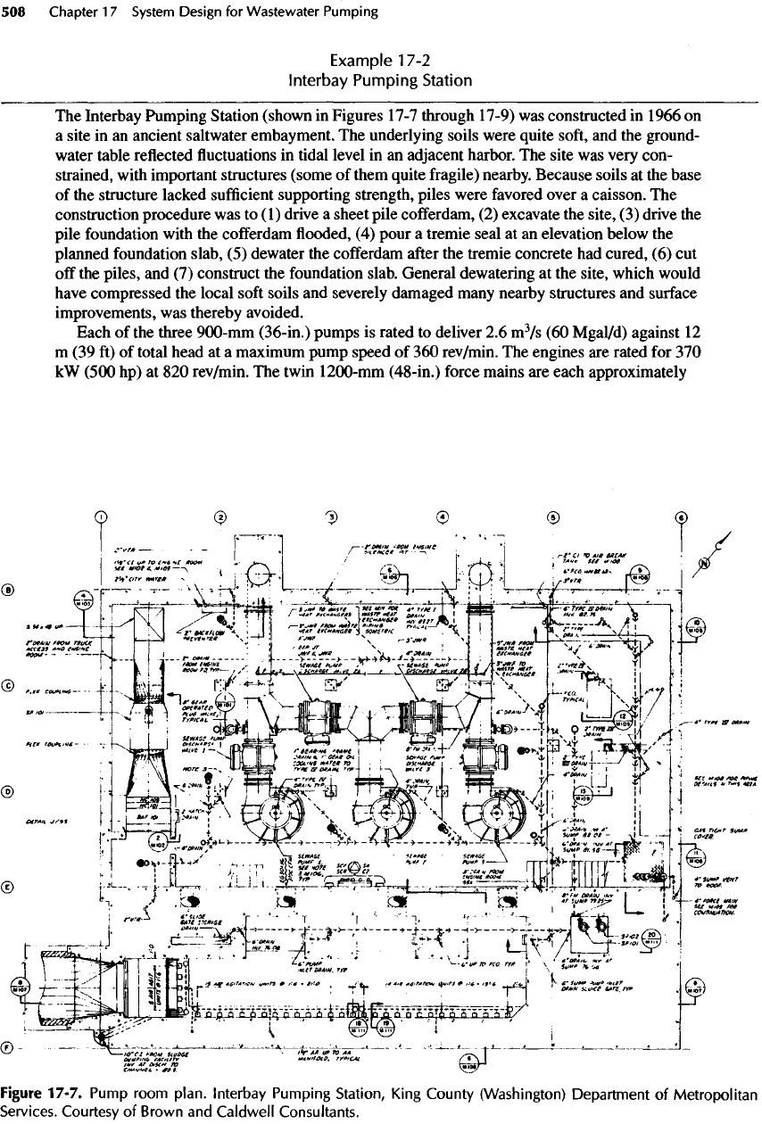
Figure
17-7.
Pump
room
plan,
lnterbay
Pumping
Station,
King
County
(Washington)
Department
of
Metropolitan
Services.
Courtesy
of
Brown
and
Caldwell
Consultants.
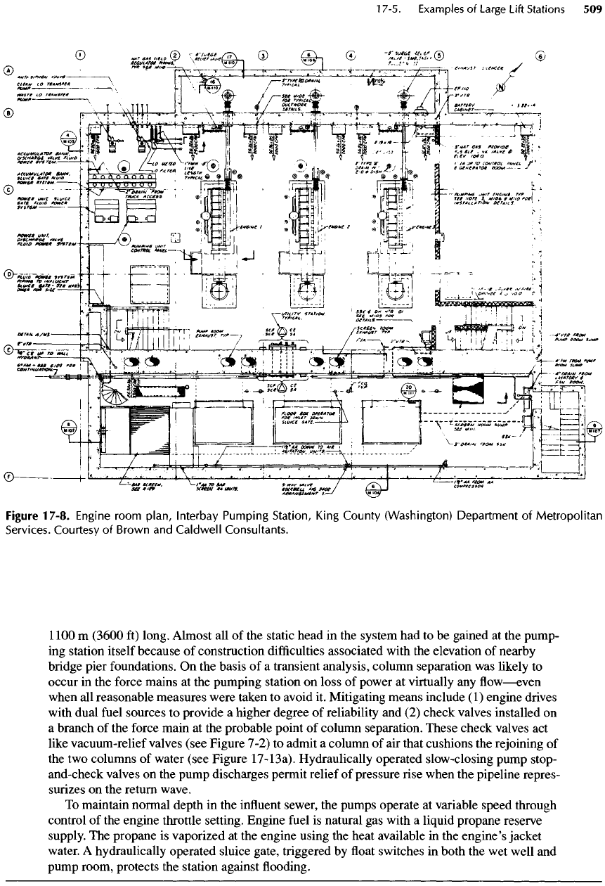
Figure 17-8.
Engine
room
plan,
lnterbay
Pumping
Station,
King
County
(Washington)
Department
of
Metropolitan
Services.
Courtesy
of
Brown
and
Caldwell
Consultants.
1100
m
(3600
ft)
long. Almost
all of the
static head
in the
system
had to be
gained
at the
pump-
ing
station itself because
of
construction
difficulties
associated with
the
elevation
of
nearby
bridge pier foundations.
On the
basis
of a
transient analysis, column separation
was
likely
to
occur
in the
force mains
at the
pumping station
on
loss
of
power
at
virtually
any flow—even
when
all
reasonable measures were taken
to
avoid
it.
Mitigating means include
(1)
engine drives
with
dual
fuel
sources
to
provide
a
higher degree
of
reliability
and (2)
check valves
installed
on
a
branch
of the
force main
at the
probable point
of
column separation. These check valves
act
like vacuum-relief valves (see Figure 7-2)
to
admit
a
column
of air
that cushions
the
rejoining
of
the two
columns
of
water (see Figure
17-13a).
Hydraulically
operated slow-closing pump stop-
and-check valves
on the
pump discharges permit relief
of
pressure rise when
the
pipeline repres-
surizes
on the
return wave.
To
maintain normal depth
in the
influent
sewer,
the
pumps operate
at
variable speed through
control
of the
engine throttle setting. Engine
fuel
is
natural
gas
with
a
liquid propane reserve
supply.
The
propane
is
vaporized
at the
engine using
the
heat available
in the
engine's
jacket
water.
A
hydraulically operated sluice gate, triggered
by float
switches
in
both
the wet
well
and
pump
room, protects
the
station against
flooding.
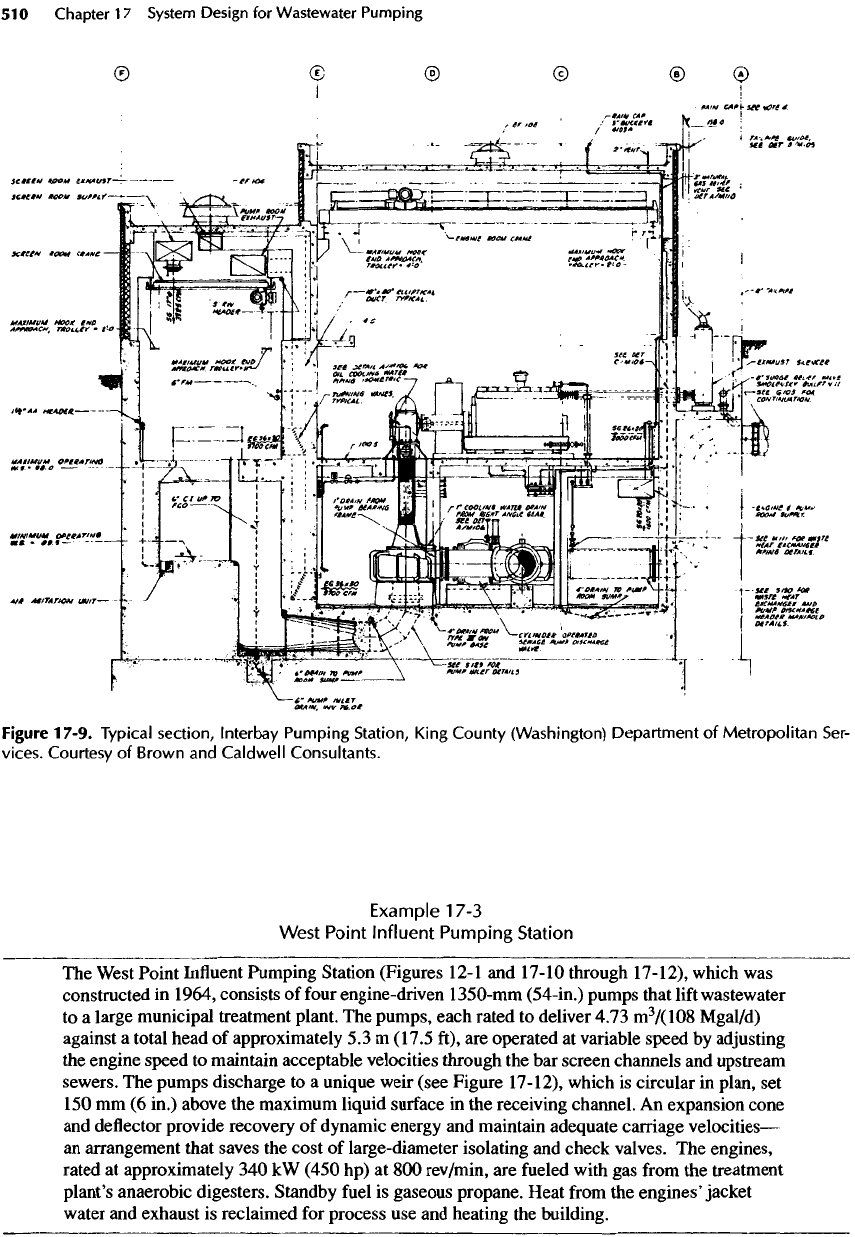
Figure
17-9.
Typical
section,
lnterbay
Pumping
Station,
King
County
(Washington)
Department
of
Metropolitan
Ser-
vices.
Courtesy
of
Brown
and
Caldwell
Consultants.
Example
17-3
West
Point Influent Pumping Station
The
West
Point
Influent
Pumping Station (Figures 12-1
and
17-10 through 17-12), which
was
constructed
in
1964, consists
of
four
engine-driven
1350-mm
(54-in.) pumps that
lift
wastewater
to a
large municipal treatment plant.
The
pumps, each rated
to
deliver 4.73
m
3
/(108
Mgal/d)
against
a
total head
of
approximately
5.3 m
(17.5 ft),
are
operated
at
variable speed
by
adjusting
the
engine speed
to
maintain acceptable velocities through
the bar
screen channels
and
upstream
sewers.
The
pumps discharge
to a
unique weir (see Figure 17-12), which
is
circular
in
plan,
set
150 mm (6
in.) above
the
maximum liquid surface
in the
receiving channel.
An
expansion
cone
and
deflector
provide recovery
of
dynamic energy
and
maintain adequate carriage
velocities—
an
arrangement that saves
the
cost
of
large-diameter isolating
and
check valves.
The
engines,
rated
at
approximately
340 kW
(450
hp) at 800
rev/min,
are
fueled
with
gas from the
treatment
plant's anaerobic digesters. Standby
fuel
is
gaseous propane. Heat
from
the
engines'jacket
water
and
exhaust
is
reclaimed
for
process
use and
heating
the
building.
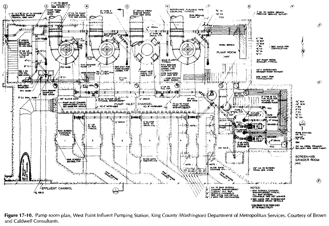
Figure
17-10.
Pump
room
plan,
West Point Influent Pumping
Station,
King County (Washington)
Department
of
Metropolitan
Services.
Courtesy
of
Brown
and
Caldwell Consultants.
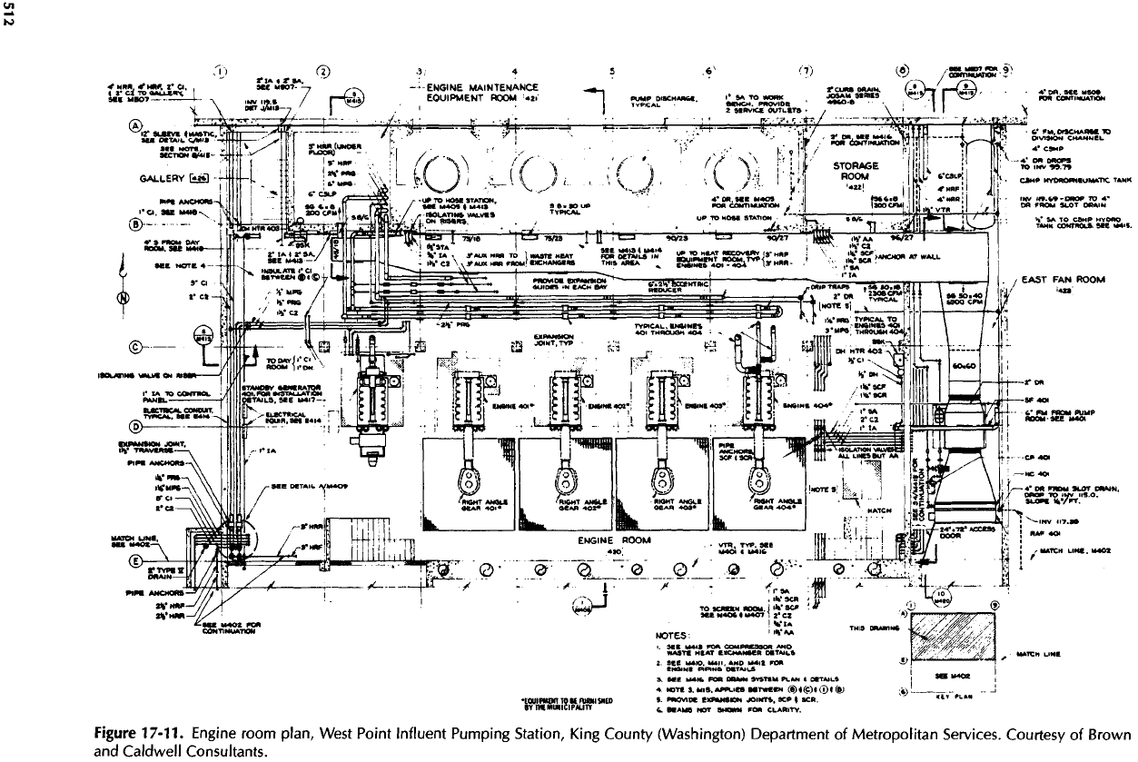
Figure
17-11.
Engine
room
plan,
West Point Influent Pumping
Station,
King County (Washington) Department
of
Metropolitan
Services.
Courtesy
of
Brown
and
Caldwell Consultants.
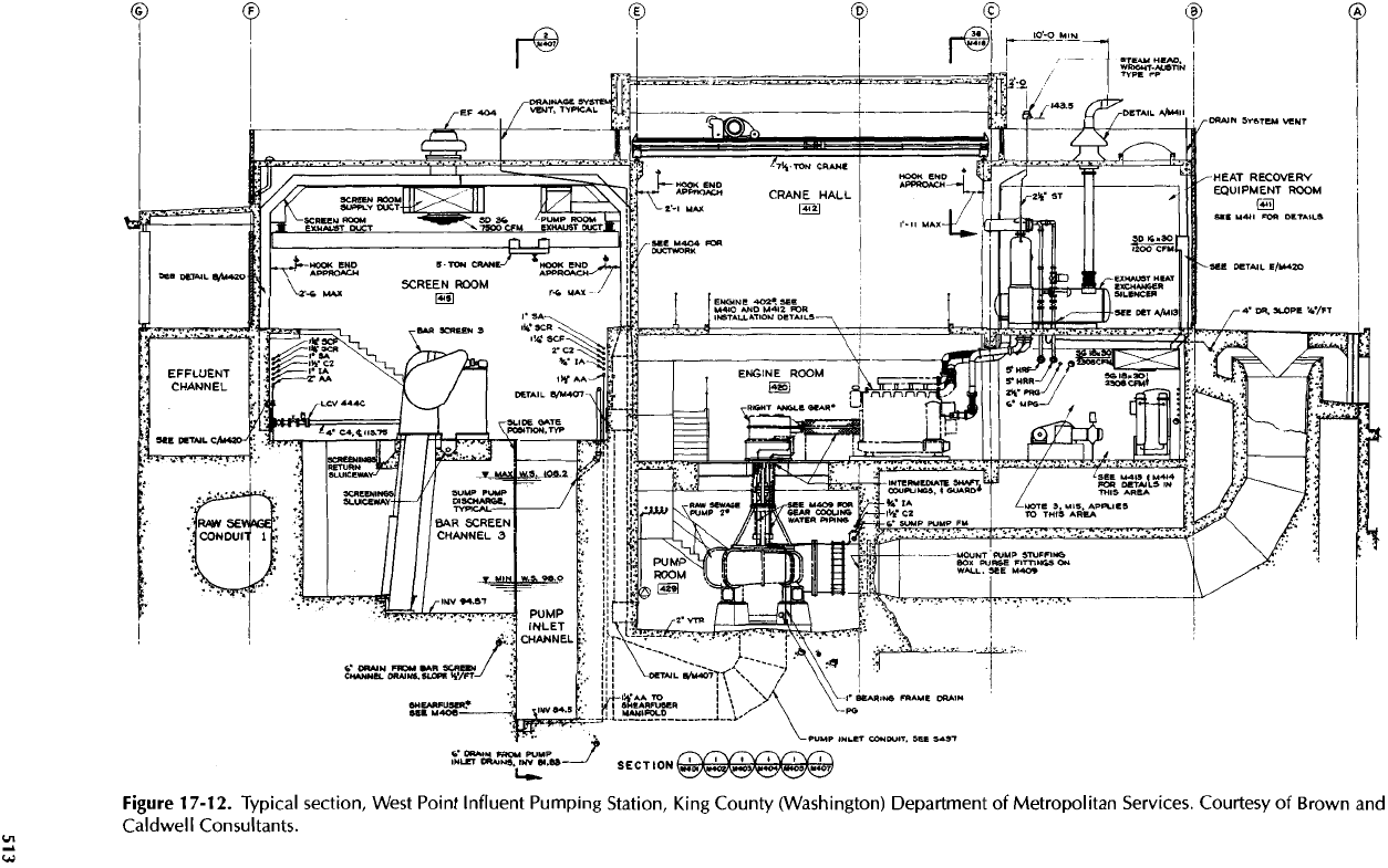
Figure
17-12.
Typical
section,
West Point Influent Pumping
Station,
King County (Washington) Department
of
Metropolitan
Services.
Courtesy
of
Brown
and
Caldwell
Consultants.
1
7-6.
Examples
of
Medium-Size
Lift
Stations
As in
Section 17-5,
all of the
pumping stations
described
in
this section work well, meet
the
design
objectives,
and are
neat, clean,
and
virtually odor-
less—even
after
10 to 30 yr of
service.
All
were
designed
to
minimize
the
size
and
depth
of the wet
wells
by
incorporating
V/S
pumps.
All
have ventila-
tion
systems that meet
the
recommendations
in
Chap-
ter 23. Air is
blown
in
near
the
ceiling
and
removed
by
a
powered exhaust system
from
the
lowest level
to
produce
a
slight vacuum (about
6 mm of
water col-
umn)
in the wet
well
to
ensure
a
safe
and
corrosion-
free
environment
for
both equipment
and
personnel.
Note
that ease
of
access, adequate room
for
mainte-
nance
and
repairs,
and a
minimum size
of
footprint
were obtained
by
following
the
equipment layout
shown
in
Figures 12-20
and
12-22.
All of
these station have trench-type
wet
wells
designed before
the
advent
of the
ogee
ramp,
so
they
are
cleaned
by
water coursing along
the
trench
at
only
subcritical
velocities.
Consequently,
not all
sludge
is
usually
removed,
and
there
is an
average residual
depth
of
about
50 mm (2
in.)
of
hard sludge remaining
after
cleaning
—
a
depth that could
be
reduced some-
what
by
modifying
the
operating
procedure.
(All
scum,
incidentally,
is
removed.) Nevertheless,
the
cleaning
is
effective
in
suppressing
odors.
The
Kirkland Pumping Station appeared
to be one
of
the
most typical
or
representative
of the
Seattle-
area stations with
the
original trench-type
wet
well
design. Thus
it
became
the
prototype
for the
model
studies described
in
Chapter
12.
Critique
The wet
well
is
covered
by a
light grating that must
be
removed section
by
section
for
washing grease
off the
walls. Gratings were omitted
in
some
of the
other
Seattle-area pumping stations
in
favor
of a
walkway
beside
the wet
well
for
easy access
for
hosing
walls
—
a
feature
much
preferred
by the
operators.
The
walls
of the wet
well were coated with coal-tar
epoxy.
After
30 yr of
service,
the
coating
is
beginning
to
peel.
Lining with
PVC is
much more expensive,
but
linings
last
far
longer.
Of
course,
it is
also expensive
to
renew coatings
in an
operating
wet
well.
Observing
the
cleaning procedure
at
Kirkland
and
the
water splashing onto
the
trench
floor,
losing
energy that could
be
used
to
create
supercritical
velocities along
the
trench, prompted
the
idea that
an
ogee
ramp would make cleaning more
effective.
From
the
model tests
described
in
Chapter
12, the
cleaning
was at
least
50
times more
effective
as
mea-
sured
by the
time required
to
remove
all
solids.
Regardless
of
whether time
is the
means used
to
rate
cleaning effectiveness,
the
ogee
ramp
is a
decided
improvement.
The
Kirkland Pumping Station serves
as an
out-
standing example
of the
importance
of
good mainte-
nance. Aside
from
some areas
in the wet
well where
the
coating
has
peeled,
the
station
has the
appearance
of
one
built only
a
year
or so
ago.
Example
17-4
Kirkland
Pumping
Station
The
Kirkland Pumping Station (shown
in
Figures 17-13
and
17-14)
was
constructed
in
1965
in
the
downtown area
of a
small city
on the
outskirts
of a
large metropolitan area.
The
station
replaced
a
wastewater treatment plant
as a
part
of a
regionalization project. Because
the
incoming
sewer would
be
only
a few
feet
below
the
existing grade, horizontal pumps were
selected
over
vertical
units
to
keep
the
station
profile
as low as
possible.
By
chance,
the
owner
had two
pumps
(surplus
from
an
abandoned station) equipped with two-speed motors that could
satisfy
project
requirements.
The
existing impellers were replaced
to
improve solids-passing capability.
The
sec-
ond
(lower) motor
speed,
however,
was too low
and, therefore,
was not
used. Instead,
the
pumps
were converted
to V/S
operation
by
using eddy-current couplings.
A
duplicate third pump
was
powered with
a new
single-speed
motor
to
complete
the
main pumping units
for the new
station.
To
avoid
any
outward indication
of the
station's purpose,
the
large transformer
and
high-volt-
age
switchgear
were enclosed within
the
station's superstructure. Each pump delivers
0.11
m
3
/s
(2.5
Mgal/d)
against
a
rated head
of
57.6
m
(189
ft) at
1750
rev/min.
The
suction bells
are 400 mm
(16
in.)
in
outside diameter.
At
maximum
flow for one
pump,
the
intake entrance velocity based
on
the
OD of the
bell
is
0.85
m/s
(2.78
ft/s)
and the
suction pipe velocity
is
2.1
m/s
(6.8
ft/s).
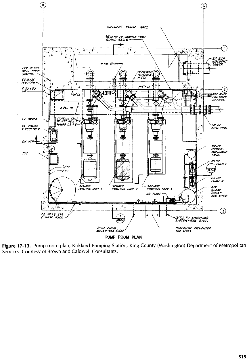
Figure
17-13.
Pump room
plan,
Kirkland Pumping Station, King County (Washington) Department
of
Metropolitan
Services.
Courtesy
of
Brown
and
Caldwell Consultants.
