Pumping Station Desing - Second Edition by Robert L. Sanks, George Tchobahoglous, Garr M. Jones
Подождите немного. Документ загружается.

likewise produce
60 Hz
voltage when rotated
at 30
revolutions
per
second.
In a
multi-pole generator,
the
required rotational speed
in
revolutions
per
minute
to
produce
60 Hz
voltage
is
7200/P,
where
P is the
num-
ber of
north
and
south
poles
(always
an
even number).
DC
generators with commutators
are
always
arranged with
the
magnets
on the
stationary member
(the
field) and the
coils
on the
rotating member
to
facilitate
commutator construction. Most
ac
genera-
tors
are
arranged with
a
rotating
field,
and,
to
elimi-
nate
the
slip rings that would
be
required
to
conduct
the
generated current
from
the
rotating member,
the
coils
are on the
stationary member. Slip rings
and
commutators
are a
significant
source
of
wear
and
maintenance.
Inductance
When current
flows in a
conductor,
a
magnetic
field
forms
that envelops
the
conductor
for its
full
length.
If
the
current
is
steady,
the field is
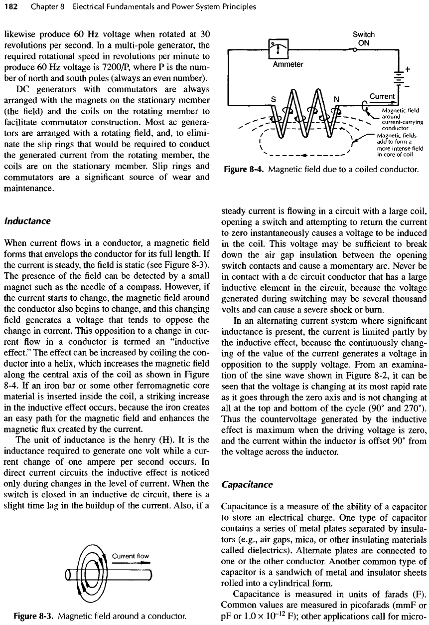
static (see Figure 8-3).
The
presence
of the field can be
detected
by a
small
magnet such
as the
needle
of a
compass. However,
if
the
current starts
to
change,
the
magnetic
field
around
the
conductor also begins
to
change,
and
this changing
field
generates
a
voltage that tends
to
oppose
the
change
in
current. This opposition
to a
change
in
cur-
rent
flow in a
conductor
is
termed
an
"inductive
effect."
The
effect
can be
increased
by
coiling
the
con-
ductor
into
a
helix, which increases
the
magnetic
field
along
the
central axis
of the
coil
as
shown
in
Figure
8-4.
If an
iron
bar or
some other ferromagnetic core
material
is
inserted
inside
the
coil,
a
striking increase
in
the
inductive
effect
occurs, because
the
iron creates
an
easy path
for the
magnetic
field and
enhances
the
magnetic
flux
created
by the
current.
The
unit
of
inductance
is the
henry (H).
It is the
inductance
required
to
generate
one
volt while
a
cur-
rent change
of one
ampere
per
second occurs.
In
direct current circuits
the
inductive
effect
is
noticed
only
during changes
in the
level
of
current. When
the
switch
is
closed
in an
inductive
dc
circuit, there
is a
slight
time
lag in the
buildup
of the
current. Also,
if a
Figure
8-3.
Magnetic
field
around
a
conductor.
Figure
8-4.
Magnetic
field
due to a
coiled
conductor.
steady current
is flowing in a
circuit with
a
large coil,
opening
a
switch
and
attempting
to
return
the
current
to
zero instantaneously causes
a
voltage
to be
induced
in
the
coil.
This voltage
may be
sufficient
to
break
down
the air gap
insulation between
the
opening
switch
contacts
and
cause
a
momentary arc. Never
be
in
contact with
a dc
circuit conductor that
has a
large
inductive
element
in the
circuit, because
the
voltage
generated during switching
may be
several thousand
volts
and can
cause
a
severe shock
or
burn.
In
an
alternating current system where
significant
inductance
is
present,
the
current
is
limited partly
by
the
inductive
effect,
because
the
continuously chang-
ing of the
value
of the
current generates
a
voltage
in
opposition
to the
supply voltage. From
an
examina-
tion
of the
sine wave shown
in
Figure 8-2,
it can be
seen that
the
voltage
is
changing
at its
most rapid rate
as
it
goes through
the
zero
axis
and is not
changing
at
all at the top and
bottom
of the
cycle (90°
and
270°).
Thus
the
countervoltage
generated
by the
inductive
effect
is
maximum when
the
driving voltage
is
zero,
and the
current within
the
inductor
is
offset
90°
from
the
voltage across
the
inductor.
Capacitance
Capacitance
is a
measure
of the
ability
of a
capacitor
to
store
an
electrical charge.
One
type
of
capacitor
contains
a
series
of
metal plates separated
by
insula-
tors (e.g.,
air
gaps, mica,
or
other insulating materials
called dielectrics). Alternate plates
are
connected
to
one or the
other conductor. Another common type
of
capacitor
is a
sandwich
of
metal
and
insulator sheets
rolled
into
a
cylindrical
form.
Capacitance
is
measured
in
units
of
farads
(F).
Common values
are
measured
in
picofarads
(mmF
or
pF or 1.0 x
10~
12
F);
other applications call
for
micro-
farads
(flF
or 1.0 x
1O
-6
F). In
power system work,
the
capacitance
is
usually designated
in
terms
of the
reac-
tive
power
or
reactive kilovolt amperes
(kVARs)
required
from
an
alternating current source
of a
spe-
cific
nominal voltage.
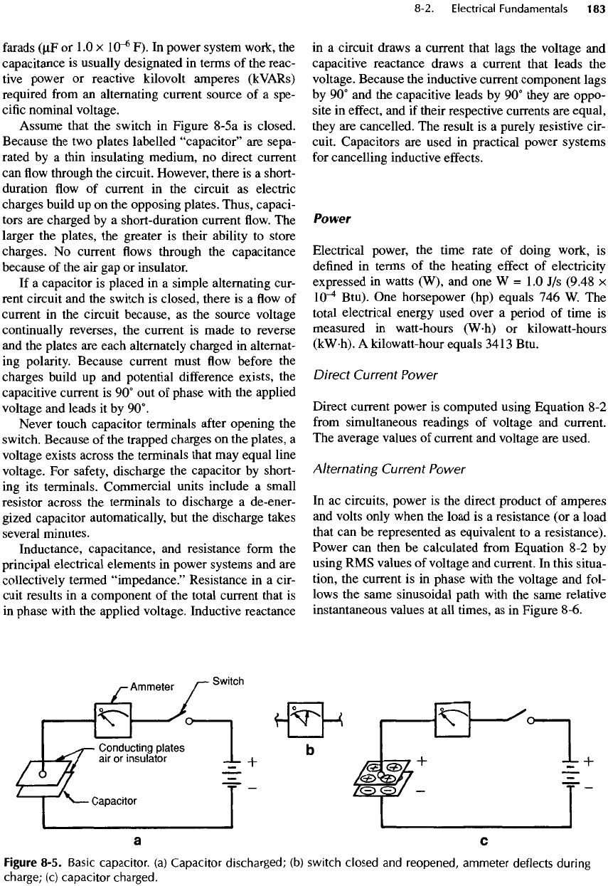
Assume
that
the
switch
in
Figure 8-5a
is
closed.
Because
the two
plates labelled
"capacitor"
are
sepa-
rated
by a
thin insulating medium,
no
direct current
can
flow
through
the
circuit. However, there
is a
short-
duration
flow of
current
in the
circuit
as
electric
charges build
up on the
opposing
plates.
Thus, capaci-
tors
are
charged
by a
short-duration current
flow. The
larger
the
plates,
the
greater
is
their ability
to
store
charges.
No
current
flows
through
the
capacitance
because
of the air gap or
insulator.
If
a
capacitor
is
placed
in a
simple alternating cur-
rent circuit
and the
switch
is
closed,
there
is a flow of
current
in the
circuit because,
as the
source voltage
continually
reverses,
the
current
is
made
to
reverse
and
the
plates
are
each alternately charged
in
alternat-
ing
polarity. Because current must
flow
before
the
charges build
up and
potential
difference
exists,
the
capacitive
current
is 90° out of
phase with
the
applied
voltage
and
leads
it by
90°.
Never
touch capacitor terminals
after
opening
the
switch.
Because
of the
trapped charges
on the
plates,
a
voltage
exists across
the
terminals that
may
equal line
voltage.
For
safety,
discharge
the
capacitor
by
short-
ing
its
terminals. Commercial units include
a
small
resistor
across
the
terminals
to
discharge
a
de-ener-
gized
capacitor automatically,
but the
discharge takes
several minutes.
Inductance,
capacitance,
and
resistance
form
the
principal electrical elements
in
power systems
and are
collectively termed
"impedance."
Resistance
in a
cir-
cuit results
in a
component
of the
total current that
is
in
phase
with
the
applied voltage. Inductive reactance
in
a
circuit draws
a
current that lags
the
voltage
and
capacitive reactance draws
a
current that leads
the
voltage. Because
the
inductive current component lags
by
90° and the
capacitive
leads
by 90°
they
are
oppo-
site
in
effect,
and if
their respective currents
are
equal,
they
are
cancelled.
The
result
is a
purely resistive cir-
cuit. Capacitors
are
used
in
practical power systems
for
cancelling inductive
effects.
Power
Electrical power,
the
time rate
of
doing work,
is
defined
in
terms
of the
heating
effect
of
electricity
expressed
in
watts (W),
and one W = 1.0 J/s
(9.48
x
10"^
Btu).
One
horsepower (hp)
equals
746 W. The
total electrical energy used over
a
period
of
time
is
measured
in
watt-hours
(W-h)
or
kilowatt-hours
(kW-h).
A
kilowatt-hour equals 3413 Btu.
Direct Current Power
Direct current power
is
computed using Equation
8-2
from
simultaneous readings
of
voltage
and
current.
The
average values
of
current
and
voltage
are
used.
Alternating
Current Power
In
ac
circuits, power
is the
direct product
of
amperes
and
volts only when
the
load
is a
resistance
(or a
load
that
can be
represented
as
equivalent
to a
resistance).
Power
can
then
be
calculated
from
Equation
8-2 by
using
RMS
values
of
voltage
and
current.
In
this situa-
tion,
the
current
is in
phase with
the
voltage
and
fol-
lows
the
same sinusoidal path with
the
same relative
instantaneous values
at all
times,
as in
Figure 8-6.
Figure 8-5. Basic
capacitor,
(a)
Capacitor
discharged;
(b)
switch
closed
and
reopened,
ammeter
deflects
during
charge;
(c)
capacitor
charged.
In
a
circuit containing pure inductance,
the
product
of
the
voltage
and
current
is
termed reactive volt-
amperes.
The two
values
are 90° out of
phase,
so the
real product
(or
power) averaged over
a
cycle
is
zero.
In
practical inductive circuits, there
is
always significant
resistance,
and the
current lags
the
voltage
by
some
angle
less than
90° as
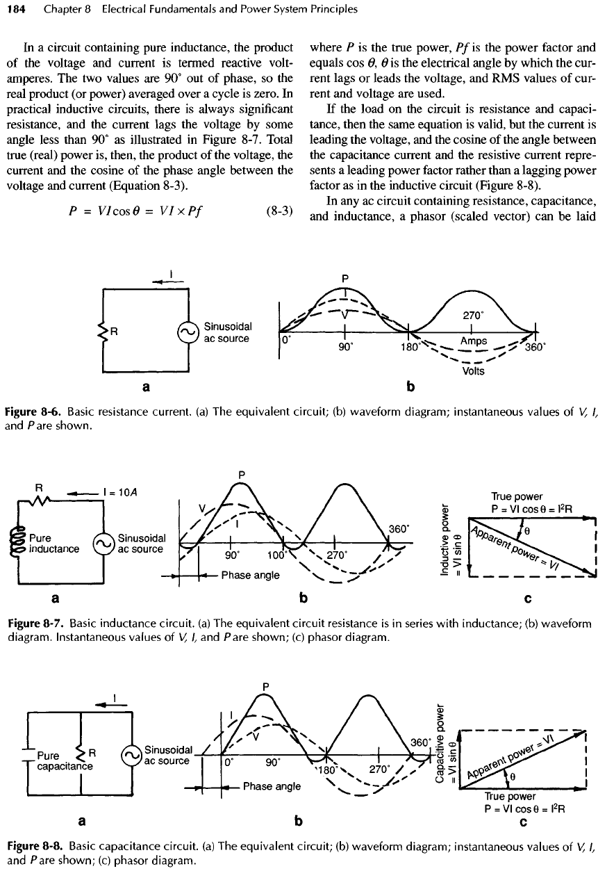
illustrated
in
Figure 8-7. Total
true
(real) power
is,
then,
the
product
of the
voltage,
the
current
and the
cosine
of the
phase angle between
the
voltage
and
current (Equation 8-3).
P
=
VI
cos O =
VIxPf
(8-3)
where
P is the
true power,
Pf
is the
power
factor
and
equals
cos 0, 6 is the
electrical angle
by
which
the
cur-
rent lags
or
leads
the
voltage,
and RMS
values
of
cur-
rent
and
voltage
are
used.
If
the
load
on the
circuit
is
resistance
and
capaci-
tance, then
the
same equation
is
valid,
but the
current
is
leading
the
voltage,
and the
cosine
of the
angle between
the
capacitance current
and the
resistive current repre-
sents
a
leading power factor rather than
a
lagging power
factor
as in the
inductive circuit (Figure 8-8).
In
any ac
circuit containing resistance, capacitance,
and
inductance,
a
phasor (scaled vector)
can be
laid
Figure 8-6.
Basic
resistance
current,
(a) The
equivalent
circuit;
(b)
waveform
diagram;
instantaneous values
of V,
I,
and
Pare shown.
Figure 8-7.
Basic
inductance
circuit,
(a) The
equivalent
circuit
resistance
is in
series
with
inductance;
(b)
waveform
diagram. Instantaneous values
of V,
I,
and
Pare
shown;
(c)
phasor
diagram.
Figure
8-8.
Basic
capacitance
circuit,
(a) The
equivalent
circuit;
(b)
waveform diagram; instantaneous values
of V,
I,
and
Pare
shown;
(c)
phasor diagram.
out
on the
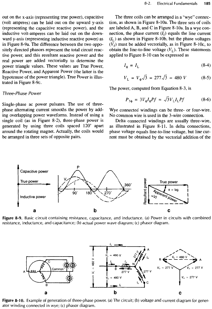
x-axis (representing true power), capacitive
(volt
amperes)
can be
laid
out on the
upward y-axis
(representing
the
capacitive reactive power),
and the
inductive
volt-amperes
can be
laid
out on the
down-
ward
y-axis (representing inductive reactive power)
as
in
Figure 8-9a.
The
difference
between
the two
oppo-
sitely directed phasors represent
the
total circuit reac-
tive
power,
and
this resultant reactive power
and the
real power
are
added vectorially
to
determine
the
power
triangle values. These values
are
True Power,
Reactive Power,
and
Apparent Power (the latter
is the
hypotenuse
of the
power triangle). True Power
is
illus-
trated
in
Figure
8-9c.
Three-Phase
Power
Single-phase
ac
power pulsates.
The use of
three-
phase alternating current smooths
the
power
by
add-
ing
overlapping power waveforms. Instead
of
using
a
single coil
(as in
Figure 8-2), three-phase power
is
generated
by
using three coils spaced 120° apart
around
the
rotating magnet. Actually,
the
coils would
be
arranged
in
three sets
of
opposite pairs.
The
three coils
can be
arranged
in a
"wye"
connec-
tion,
as
shown
in
Figure
8-
1Oa.
The
three sets
of
coils
are
labeled
A, B, and C in
Figure
8-
1Oa.
In a wye
con-
nection,
the
phase current
(7
f
)
equals
the
line current
(7
L
)
as
shown
in
Figure
8-
1Ob,
but the
phase voltages
(Vf)
must
be
added vectorially,
as in
Figure
8-
1Oc,
to
obtain
the
line-to-line voltage
(V
L
).
These statements
applied
to
Figure
8-10
can be
expressed
as
/*
=
IL
(8-4)
V
L
=
V^
73
=
277^3
= 480 V
(8-5)
The
power, computed
from
Equation 8-3,
is
P^
=
3VV«
P
/
=
V3V
L
/
L
P/
(8-6)
Wye
connected windings
can be
three-
or
four-
wire.
No
common wire
is
used
in the
3-wire connection.
Delta connected windings
are
usually three-wire,
as
illustrated
in
Figure
8-11.
In
delta connections,
phase voltage equals line-to-line voltage,
but
line cur-
rent must
be
obtained
by the
vectorial
addition
of the
Figure 8-9.
Basic
circuit
containing
resistance,
capacitance,
and
inductance,
(a)
Power
in
circuits
with
combined
resistance,
inductance,
and
capacitance;
(b)
actual
power
wave
diagram;
(c)
phasor
diagram.
Figure
8-10.
Example
of
generation
of
three-phase
power,
(a) The
circuit;
(b)
voltage
and
current
diagram
for
gener-
ator
winding
connected
in
wye;
(c)
phasor
diagram.
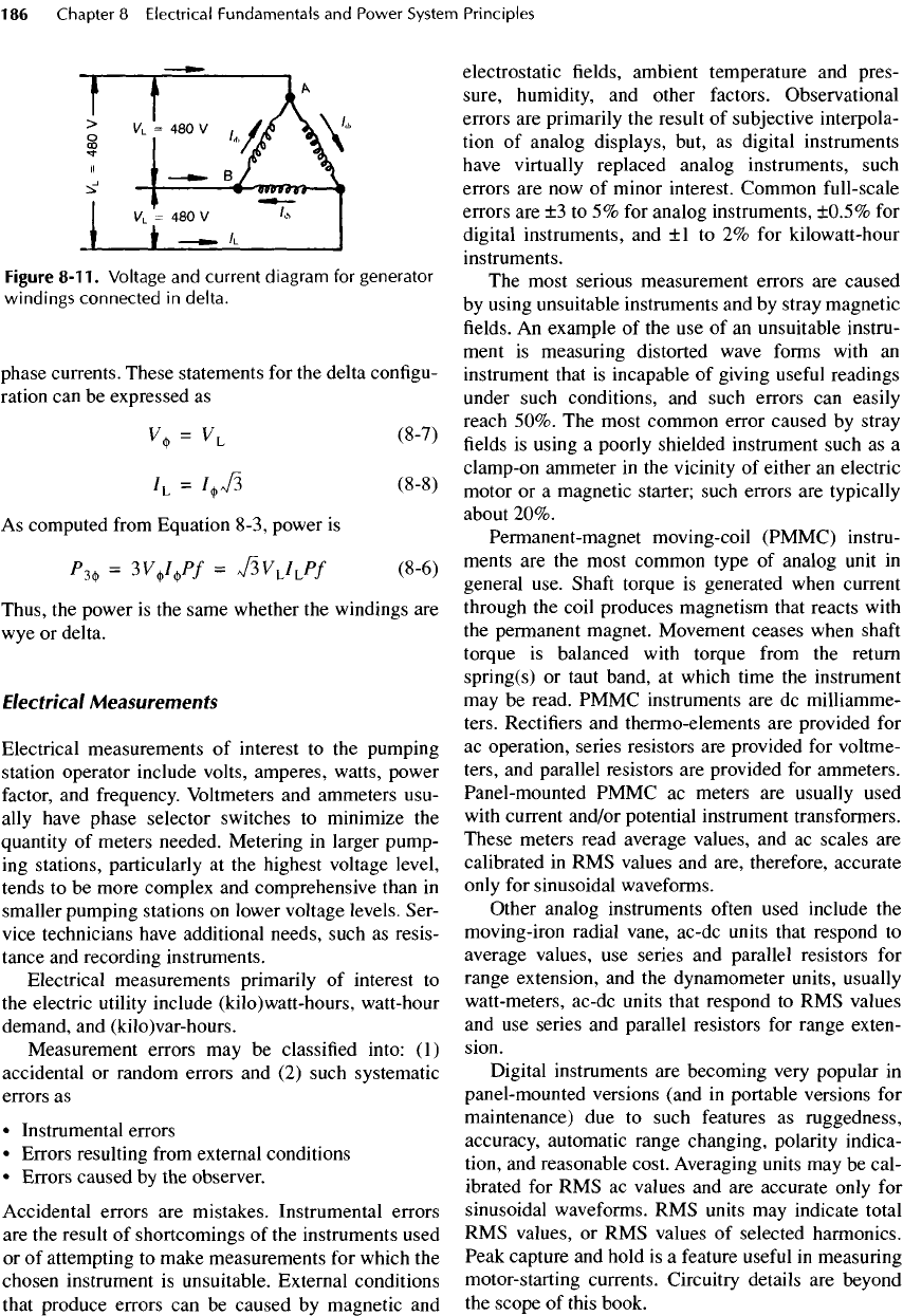
Figure
8-11.
Voltage
and
current diagram
for
generator
windings
connected
in
delta.
phase currents.
These
statements
for the
delta configu-
ration
can be
expressed
as
V)
=
V
L
(8-7)
/L
=
I^
(8-8)
As
computed
from
Equation 8-3, power
is
P^
=
3V*
F
/
=
^V
1
JJf
(8-6)
Thus,
the
power
is the
same whether
the
windings
are
wye
or
delta.
Electrical
Measurements
Electrical measurements
of
interest
to the
pumping
station
operator include volts, amperes, watts, power
factor,
and
frequency.
Voltmeters
and
ammeters usu-
ally
have phase selector switches
to
minimize
the
quantity
of
meters needed. Metering
in
larger pump-
ing
stations, particularly
at the
highest voltage level,
tends
to be
more complex
and
comprehensive than
in
smaller pumping stations
on
lower voltage levels. Ser-
vice technicians have additional needs, such
as
resis-
tance
and
recording instruments.
Electrical measurements primarily
of
interest
to
the
electric
utility
include (kilo)watt-hours, watt-hour
demand,
and
(kilo)var-hours.
Measurement
errors
may be
classified into:
(1)
accidental
or
random
errors
and (2)
such systematic
errors
as
•
Instrumental errors
•
Errors resulting
from
external conditions
•
Errors
caused
by the
observer.
Accidental
errors
are
mistakes. Instrumental
errors
are the
result
of
shortcomings
of the
instruments used
or of
attempting
to
make measurements
for
which
the
chosen instrument
is
unsuitable. External conditions
that
produce errors
can be
caused
by
magnetic
and
electrostatic
fields,
ambient temperature
and
pres-
sure, humidity,
and
other factors. Observational
errors
are
primarily
the
result
of
subjective interpola-
tion
of
analog displays, but,
as
digital instruments
have virtually
replaced
analog instruments, such
errors
are now of
minor interest. Common full-scale
errors
are ±3 to 5% for
analog instruments, ±0.5%
for
digital instruments,
and ±1 to 2% for
kilowatt-hour
instruments.
The
most serious measurement errors
are
caused
by
using unsuitable instruments
and by
stray magnetic
fields.
An
example
of the use of an
unsuitable instru-
ment
is
measuring distorted wave forms with
an
instrument that
is
incapable
of
giving
useful
readings
under
such conditions,
and
such
errors
can
easily
reach 50%.
The
most common
error
caused
by
stray
fields
is
using
a
poorly shielded instrument such
as a
clamp-on ammeter
in the
vicinity
of
either
an
electric
motor
or a
magnetic starter; such
errors
are
typically
about 20%.
Permanent-magnet moving-coil
(PMMC)
instru-
ments
are the
most common type
of
analog unit
in
general use.
Shaft
torque
is
generated when current
through
the
coil produces magnetism that reacts with
the
permanent magnet. Movement
ceases
when
shaft
torque
is
balanced with torque
from
the
return
spring(s)
or
taut
band,
at
which time
the
instrument
may
be
read.
PMMC
instruments
are dc
milliamme-
ters. Rectifiers
and
thermo-elements
are
provided
for
ac
operation,
series
resistors
are
provided
for
voltme-
ters,
and
parallel resistors
are
provided
for
ammeters.
Panel-mounted PMMC
ac
meters
are
usually used
with
current and/or potential instrument transformers.
These meters read average values,
and ac
scales
are
calibrated
in RMS
values
and
are, therefore, accurate
only
for
sinusoidal waveforms.
Other analog instruments
often
used include
the
moving-iron radial vane, ac-dc units that respond
to
average values,
use
series
and
parallel resistors
for
range extension,
and the
dynamometer units,
usually
watt-meters, ac-dc units that respond
to RMS
values
and
use
series
and
parallel
resistors
for
range exten-
sion.
Digital instruments
are
becoming very popular
in
panel-mounted versions (and
in
portable versions
for
maintenance)
due to
such features
as
ruggedness,
accuracy, automatic range changing, polarity indica-
tion,
and
reasonable cost. Averaging units
may be
cal-
ibrated
for RMS ac
values
and are
accurate only
for
sinusoidal waveforms.
RMS
units
may
indicate total
RMS
values,
or RMS
values
of
selected harmonics.
Peak
capture
and
hold
is a
feature
useful
in
measuring
motor-starting currents. Circuitry details
are
beyond
the
scope
of
this book.
Panel-mounted instruments used
in ac
circuits
in
new
pumping stations should
be
digital units
that
respond
to
true
RMS
values.
Resistance
is not
ordinarily measured directly.
Instead,
the
instruments have
an
integral voltage
source (battery, hand-cranked generator,
or
other
dc
power
supply),
and
current through
the
resistor
is
measured
and
displayed
on the
selected
scale
in
terms
of
ohms.
The
portable clamp-on
ac
ammeter
has a
movable
half
-jaw
that enables
the
operator
to
slip
it on
over
an
insulated
conductor
for
fast,
easy,
and
safe
current
measurement.
The
jaws, when
fully
closed,
form
an
iron core that encircles
the
conductor
and
intercepts
the
magnetic
field
generated
by the
current
in the
con-
ductor.
By
transformer action,
a
voltage
is
induced
in
a
secondary coil wound
on the
iron core.
The
voltage
is
measured
and
read
in
terms
of
amperes. Encircling
more than
one
phase
(or a
phase
and
neutral)
in the
jaws
cancels
the
magnetic
field and
causes
a
spurious
reading
or
none
at
all. These instruments
are
usually
multipurpose units that
can
also measure voltage
and
resistance.
Ac
watt-hour meters
are
used
to
measure
the flow
or
usage
of
electrical
energy
by
means
of the
induc-
tion
motor principle. Torque
is
produced
on the
alumi-
num
rotor disk
by
means
of
magnetic
fluxes
from
current
and
voltage coils. This torque,
and
thus disk
rotational speed,
is
proportional
to
instantaneous
power.
The
disk drives
a
mechanical
or
digital register
that
integrates disk speed with time, producing
a
watt-
hour
(or
kilowatt-hour) reading.
A
three-phase meter
uses
two
disks. Practical error limits
are
within about
±1 to 2%.
The
maximum amount
of
electrical energy used
in
a
given period
is
measured with
a
demand meter,
often
integral
with pumping station kilowatt-hour meters.
The
maximum demand
in any one
year typically
determines
the
power company's demand charge
for
the
next year, because their distribution system must
be
able
to
provide
the
customer with that much
energy,
regardless
of
whether
it is
used
at
other times.
Thus,
for
example,
a
storm water pumping station
demand charge
for an
entire year
may
reflect
the
effect
of
one
3
-day
storm last year, even though
the
pumping
station
may be
unused
for
1 1
months.
Basic Electrical
Calculations
The
relation between resistance, volts,
and
current
is
given
by
Ohm's law, Equation
8-1.
R =
VIl
where
R is
measured
in
ohms (Q),
V is
volts,
and / is
current
in
amperes (A).
The
total resistance
of
several resistances
in
series
is the sum of the
individual resistances.
R
T
=
R
1
+R
2
+
...
+R
N
(8-9)
The
inverse
of the
total resistance
of
several resis-
tances
in
parallel
is the sum of the
inverse
of the
indi-
vidual
resistances.
-L
=
I
+
I
+
....+
1
(8-10)
/?
T
/V
1
R
2
RN
where
R
T
is the
total resistance
and
R
1
, R
2
,
and so
forth
are
individual resistances,
all in
ohms.
Lest
the
reader think that
all
electrical calculations
in
the
real world
are as
simple
as
presented above,
one
kind
of
calculation that
an
electrical engineer would
make every
day is to find the
voltage drop through
a
simple electrical power feeder
E
D
=
E
s
-
E
L
where
the
relation between
E$
and
E
L
is
given
by
Equation
8-11.
i
E
s
=
l(E
L
cosQ
+
RI)
2
+
(E
L
sinO
+
XI)
2
~]
(8-11)
The
voltage drop through
the
power feeder
is
£
D
,
E
s
is
the
voltage
at the
source,
E
L
is the
voltage across
the
load,
Q is the
angle whose cosine
is the
load power
factor,
R is the
resistance
of the
circuit
in
ohms,
/ is
the
line current
in
amperes,
and X is the
reactance
of
the
circuit (usually inductive)
in
ohms.
The
equation
is
best solved
by
means
of a
computer program.
8-3. Power
and
Control
System
Elements
Solenoids
A
solenoid, illustrated
in
Figure 8-12,
is an
electro-
magnet arranged
to
produce linear mechanical motion.
An
electromagnet
is
formed
by a
number
of
turns
of
wire around
an
iron core, solid
for dc but for ac,
lami-
nated
to
reduce eddy currents.
An
energized electro-
magnet draws
an
iron armature toward
it by
magnetic
attraction.
The
armature
may be
connected
by a
suit-
able mechanical linkage
to
another object.
The
range
of
motion
is
small, perhaps
2 to 5 mm,
except
for
long
hollow core types where
the
core
is
drawn
in,
perhaps
25
mm (1
in.)
or
more.
A
common application
in
pumping
stations
is the
solenoid valve. Energizing
the
solenoid causes
the
valve
to
operate
from
open
to
closed
or
from
closed
to
open position. Other motions
are
possible, depending
on the
design
of the
linkage
mechanism. Solenoids
are
also used
to
operate braking
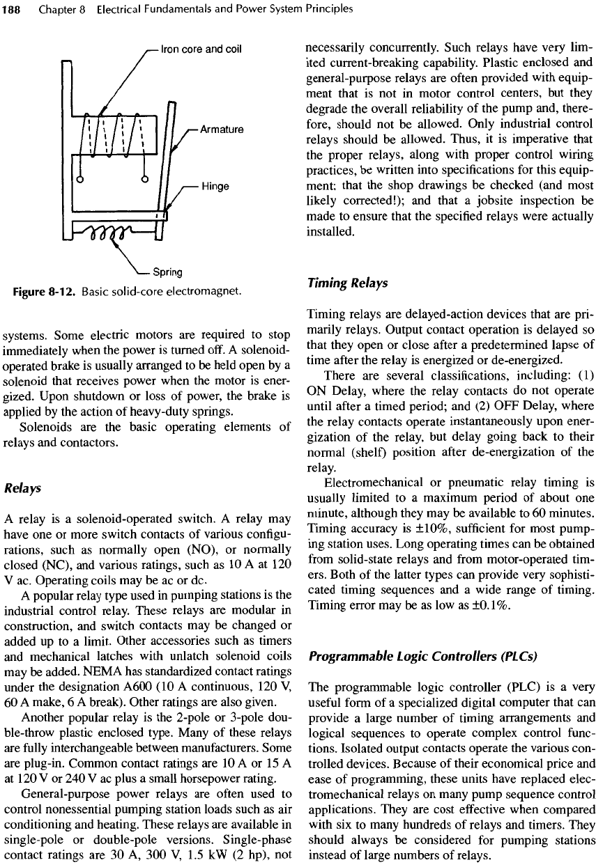
Figure
8-12.
Basic
solid-core
electromagnet.
systems.
Some electric motors
are
required
to
stop
immediately
when
the
power
is
turned off.
A
solenoid-
operated
brake
is
usually arranged
to be
held open
by a
solenoid that receives power when
the
motor
is
ener-
gized. Upon shutdown
or
loss
of
power,
the
brake
is
applied
by the
action
of
heavy-duty
springs.
Solenoids
are the
basic operating elements
of
relays
and
contactors.
Relays
A
relay
is a
solenoid-operated switch.
A
relay
may
have
one or
more switch contacts
of
various
configu-
rations, such
as
normally open (NO),
or
normally
closed (NC),
and
various ratings, such
as 10 A at 120
V
ac.
Operating coils
may be ac or dc.
A
popular relay type used
in
pumping stations
is the
industrial control relay.
These
relays
are
modular
in
construction,
and
switch contacts
may be
changed
or
added
up to a
limit. Other accessories such
as
timers
and
mechanical latches with unlatch solenoid coils
may
be
added. NEMA
has
standardized contact ratings
under
the
designation A600
(10 A
continuous,
120
V,
60 A
make,
6 A
break). Other ratings
are
also given.
Another
popular relay
is the
2-pole
or
3
-pole
dou-
ble-throw plastic enclosed type. Many
of
these relays
are
fully
interchangeable between
manufacturers.
Some
are
plug-in. Common contact ratings
are 10 A or 15 A
at
120 V or 240 V ac
plus
a
small horsepower rating.
General
-purpose
power relays
are
often
used
to
control nonessential pumping station loads such
as air
conditioning
and
heating. These relays
are
available
in
single-pole
or
double-pole versions. Single-phase
contact
ratings
are 30 A, 300 V,
1.5
kW (2
hp),
not
necessarily concurrently. Such relays have very lim-
ited current-breaking capability. Plastic
enclosed
and
general-purpose relays
are
often
provided with equip-
ment
that
is not in
motor control centers,
but
they
degrade
the
overall reliability
of the
pump and, there-
fore,
should
not be
allowed. Only industrial control
relays should
be
allowed. Thus,
it is
imperative that
the
proper relays, along with proper control wiring
practices,
be
written into specifications
for
this equip-
ment;
that
the
shop drawings
be
checked (and most
likely
corrected!);
and
that
a
jobsite
inspection
be
made
to
ensure that
the
specified relays were actually
installed.
Timing Relays
Timing relays
are
delayed-action devices that
are
pri-
marily relays. Output contact operation
is
delayed
so
that they open
or
close
after
a
predetermined lapse
of
time
after
the
relay
is
energized
or
de-energized.
There
are
several classifications, including:
(1)
ON
Delay, where
the
relay contacts
do not
operate
until
after
a
timed period;
and (2) OFF
Delay, where
the
relay contacts operate instantaneously upon ener-
gization
of the
relay,
but
delay going back
to
their
normal (shelf)
position
after
de-energization
of the
relay.
Electromechanical
or
pneumatic relay timing
is
usually
limited
to a
maximum period
of
about
one
minute, although they
may be
available
to 60
minutes.
Timing accuracy
is
±10%,
sufficient
for
most pump-
ing
station uses. Long operating times
can be
obtained
from
solid-state relays
and
from
motor-operated tim-
ers. Both
of the
latter types
can
provide very sophisti-
cated timing sequences
and a
wide range
of
timing.
Timing error
may be as low as
±0.1%.
Programmable
Logic
Controllers
(PLCs)
The
programmable logic controller (PLC)
is a
very
useful
form
of a
specialized
digital computer that
can
provide
a
large number
of
timing arrangements
and
logical sequences
to
operate complex control
func-
tions. Isolated
output
contacts operate
the
various con-
trolled devices. Because
of
their economical price
and
ease
of
programming, these units have replaced
elec-
tromechanical relays
on
many pump sequence control
applications. They
are
cost
effective
when compared
with
six to
many hundreds
of
relays
and
timers. They
should
always
be
considered
for
pumping stations
instead
of
large numbers
of
relays.
Transformers
Transformers
operate
on the
principle
of
magnetic
induction
and are
used
to
change voltage levels
in ac
systems
and to
isolate (electrically)
one
circuit
from
another.
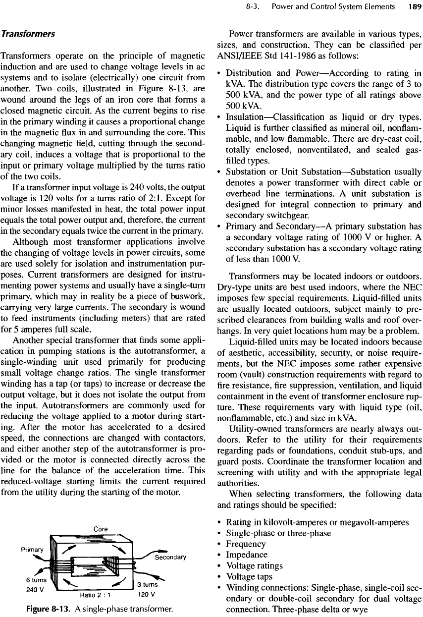
Two
coils, illustrated
in
Figure 8-13,
are
wound
around
the
legs
of an
iron core that forms
a
closed magnetic circuit.
As the
current begins
to
rise
in
the
primary winding
it
causes
a
proportional change
in
the
magnetic
flux in and
surrounding
the
core. This
changing
magnetic
field,
cutting through
the
second-
ary
coil, induces
a
voltage that
is
proportional
to the
input
or
primary voltage multiplied
by the
turns ratio
of
the two
coils.
If
a
transformer input voltage
is 240
volts,
the
output
voltage
is
120
volts
for a
turns ratio
of
2:1.
Except
for
minor
losses manifested
in
heat,
the
total power input
equals
the
total power output and, therefore,
the
current
in
the
secondary equals twice
the
current
in the
primary.
Although
most transformer applications involve
the
changing
of
voltage levels
in
power circuits, some
are
used solely
for
isolation
and
instrumentation pur-
poses. Current transformers
are
designed
for
instru-
menting power systems
and
usually have
a
single-turn
primary, which
may in
reality
be a
piece
of
buswork,
carrying
very large currents.
The
secondary
is
wound
to
feed
instruments (including meters) that
are
rated
for
5
amperes
full
scale.
Another special transformer that
finds
some appli-
cation
in
pumping stations
is the
autotransformer,
a
single-winding
unit used primarily
for
producing
small voltage change ratios.
The
single transformer
winding
has a tap (or
taps)
to
increase
or
decrease
the
output
voltage,
but it
does
not
isolate
the
output
from
the
input.
Autotransformers
are
commonly used
for
reducing
the
voltage applied
to a
motor during start-
ing.
After
the
motor
has
accelerated
to a
desired
speed,
the
connections
are
changed with contactors,
and
either another step
of the
autotransformer
is
pro-
vided
or the
motor
is
connected directly across
the
line
for the
balance
of the
acceleration time. This
reduced-voltage
starting limits
the
current required
from
the
utility
during
the
starting
of the
motor.
Figure
8-13.
A
single-phase transformer.
Power transformers
are
available
in
various types,
sizes,
and
construction. They
can be
classified
per
ANSI/IEEE
Std
141-1986
as
follows:
•
Distribution
and
Power
—
According
to
rating
in
kVA.
The
distribution type covers
the
range
of 3 to
500
kVA,
and the
power type
of all
ratings above
500
kVA.
•
Insulation
—
Classification
as
liquid
or dry
types.
Liquid
is
further
classified
as
mineral oil,
nonflam-
mable,
and low flammable.
There
are
dry-cast coil,
totally
enclosed,
nonventilated,
and
sealed
gas-
filled
types.
•
Substation
or
Unit
Substation
—
Substation
usually
denotes
a
power transformer with direct cable
or
overhead line terminations.
A
unit substation
is
designed
for
integral connection
to
primary
and
secondary switchgear.
•
Primary
and
Secondary
—
A
primary substation
has
a
secondary voltage rating
of
1000
V or
higher.
A
secondary substation
has a
secondary voltage rating
of
less
than 1000
V.
Transformers
may be
located indoors
or
outdoors.
Dry-type units
are
best
used indoors, where
the NEC
imposes
few
special requirements. Liquid-filled units
are
usually located outdoors, subject mainly
to
pre-
scribed clearances
from
building walls
and
roof over-
hangs.
In
very quiet locations
hum may be a
problem.
Liquid-filled
units
may be
located indoors
because
of
aesthetic, accessibility, security,
or
noise require-
ments,
but the NEC
imposes some rather expensive
room (vault) construction requirements with regard
to
fire
resistance,
fire
suppression, ventilation,
and
liquid
containment
in the
event
of
transformer enclosure rup-
ture. These requirements vary with liquid type (oil,
nonflammable,
etc.)
and
size
in
kVA.
Utility-owned
transformers
are
nearly always out-
doors. Refer
to the
utility
for
their requirements
regarding pads
or
foundations, conduit stub-ups,
and
guard
posts. Coordinate
the
transformer location
and
screening with utility
and
with
the
appropriate legal
authorities.
When selecting transformers,
the
following data
and
ratings should
be
specified:
•
Rating
in
kilovolt-amperes
or
megavolt-amperes
•
Single-phase
or
three-phase
•
Frequency
•
Impedance
•
Voltage ratings
•
Voltage taps
•
Winding connections: Single-phase, single-coil sec-
ondary
or
double-coil secondary
for
dual voltage
connection. Three-phase delta
or wye
•
Temperature rise
•
Basic impulse level (BIL)
•
K-rating,
if
applicable. K-rated transformers
are
specially designed
to
resist
the
heating
effects
of
currents with harmonic frequencies (multiples
of
rated frequency).
In
pumping stations, adjustable-
speed
motor controllers
are the
major source
of
har-
monic currents.
The
desired construction details should include:
•
Insulation
medium
—
dry
or
liquid type
•
Indoor
or
outdoor service
•
Accessories
—
monitoring
and
safety
devices, light-
ning
arrestors
•
Type
and
location
of
terminating facilities
•
Sound-level limitations
(if
any)
•
Manual
or
automatic load
tap
changing
•
Grounding requirements
•
Cooling
or
provisions
for
future
cooling
•
Energy conservation features.
In
pumping stations
of
more
than several
kVA
full-load
rating,
the
transformers connected
to the
utility
are
ordinarily three-phase units. Some utilities
serve small three-phase pumping stations
at 240 V
using
three pole-mounted single-phase transform-
ers.
Two
such transformers connected
in
open delta
are
sometimes used,
but
this practice should
not be
tolerated
for
fully
loaded pumps, because
the
phase
voltages
are
somewhat unbalanced
and
cause exces-
sive
phase currents
and
motor overheating.
In
larger
installations,
the
transformer
may be the
property
of
the
station owner
and may be
part
of the
switchgear
lineup.
Large transformer ownership
can be
negoti-
ated with
the
utility.
Single-phase, dry-type transformers
are
com-
monly
used
to
supply
120 V
convenience recepta-
cles, lighting,
and
small power loads, such
as
control
and
instrument
and
computer power. Three-phase
transformers
with
a
delta-wye winding connection
shown
in
Figure 8-10
are
also widely used.
The wye
connection
can
supply both three-phase
and
single-
phase loads simultaneously.
The
neutral
is
grounded
and
results
in a
uniform
potential relative
to
ground
in
all
phases.
For
long-term variations
in
supply voltage
or for
growth
in
plant load, power transformers should have
two
2.5% primary taps above normal
and two
2.5%
taps
below normal. These primary winding taps
are
usually
specified
for
de-energized reconnection.
The
impedance rating
of a
transformer
is
usually
given
in
percent
of
full
load ratings,
and it is
ordi-
narily
specified
at 5 to 8%.
This impedance limits
the
current
that would
flow in the
primary
and
secondary
systems
of the
transformer
if a
short circuit occurs
in
the
secondary system
or at the
terminals
of the
trans-
former.
Therefore,
the
impedance
(in
conjunction with
the
supply system's available short circuit current)
determines:
(1)
the
required interrupting ratings
of the
load switching devices
and
fault
current interrupting
devices
(fuses
and
circuit breakers)
and (2) the
brac-
ing
required
in
buswork.
But the
higher
the
imped-
ance,
the
higher
the
voltage regulation, particularly
during motor starting. Hence, carefully strike
a
bal-
ance
between available short circuit current
and
volt-
age
regulation.
Many
pole-mounted
and
pad-mounted transform-
ers
furnished
by the
utilities have
low
impedances,
such
as 3%, and
thus they allow relatively higher
fault
current during short circuit conditions than
do
higher
impedance units.
Low
impedance transformers
can
result
in
more expensive switchgear,
and
thus
the
cheaper low-impedance transformer
may be
poor
in
overall economy. System voltage drop during motor
starting
is,
however, less with
low
impedance trans-
formers.
Transformers
are
rated
in kVA at a
specific temper-
ature determined
by
winding resistance measurements
in
accordance
with NEMA standards.
The
transformer
temperature rating
is a
function
of the
insulation sys-
tem
used.
The
effects
of
excessive temperature rise
on
insulation
in
transformers
and
electric motors
are
identical.
See
Section 13-9
and
Table 13-2
for
more
detail.
If
proper allowance
has
been made
in the
specifi-
cations
for a
transformer, plant load increases
may
be
accommodated
by the
addition
of
cooling
fans
and/or
an oil
circulation heat exchanger system
to
allow
the
transformer
to
withstand
a
larger load
current safely.
Switches
The
types
of
switches normally applied
in
power cir-
cuits
include
the
following:
•
Disconnecting switches
•
Load interrupter
(or
load break) switches
•
Safety switches
•
Control switches.
A
disconnecting switch
is
used
for
isolating
a
circuit
or
equipment
from
the
source
of
power.
It
has no
interrupting rating
and is
intended only
for
operation after
the
circuit
has
been de-energized
by
other means.
Load interrupter switches
are
intended
for
operat-
ing
on
circuits
of 600
volts
or
above. They
are of air or
fluid-immersed
construction.
The
load break switch
is
usually
manually operated
and has a
quick-make,
quick-break operating mechanism that
operates
at a
speed independent
of the
speed
of
operation
of the
handle. When combined with
a
properly rated
fuse,
fast
fault
clearing
as
well
as
circuit isolation
can be
provided. This type
of
switch
(in a
metal clad
or
metal
enclosed unit substation lineup) serves
to
disconnect
and
protect transformers
and
medium voltage pump
motors.
It is
sometimes provided
as a
roll-out unit
for
safety
and
ease
of
maintenance. (See
ANSI/IEEE
141.)
Safety
switches
are
commonly used
for
isolating
and
disconnecting circuits
of 600 V and
below. These
switches
are
enclosed
and may be
fused
or
unfused.
A
safety
switch designed specifically
for
motor circuits
is
rated
in
horsepower
and
must
be
able
to
interrupt
the
maximum current drawn
by the
motor.
The
maxi-
mum
current
is the
stalled
or
locked rotor current,
which
is
600%
or
more
of the
rated full-load current
of
the
motor. (See
ANSI/IEEE
141.)
Control switches
are
constructed
in
many types,
sizes,
and
ratings. They
are
usually rated
for a few
amperes
and for a few
volts
to
about
250
volts
in
either
ac or dc
designs. They have large plated con-
tacts
in
most circuits,
and for
milliampere
control cir-
cuits,
the
contacts
are
usually
gold plated.
Take precautions
to
ensure that control switches
are
operated within their voltage
and
current rating
and
that
ac
switches
are not
applied
to dc
circuits.
The
nor-
mal
toggle switches
for the
control
of
lighting circuits
are in a
similar category
and
some
are
rated
not
only
"AC
only"
but
also
for the
type
of
lighting circuit.
Fuses
A
fuse
is an
overcurrent protective device with
a
cir-
cuit-opening
fusible
link
that
is
heated
and
melted
by
the
passage
of
overcurrent through
it
(per
ANSI/IEEE
100-1984).
Fuses
are
calibrated
for a
specific
melting time
for
a
specific
current that persists
for a
defined
time. Fuse
time delay
is
approximately inversely proportional
to
the
square
of the
current,
but the
exact nature
of
fuse
operation must
be
determined
by
laboratory tests
for
each type
and
rating
of
fuse.
The
resulting time-cur-
rent curves
are
plotted
on
graphs with special log-log
scales
and are
used
as
fuse
application guides.
Fuses
are
available
in a
wide range
of
voltage
and
current ratings
and
time characteristics. Fuses
may be
obtained
with
slow-blow characteristics
for
such
applications
as
motor starting.
These
fuses
must, with-
out
damage, pass
up to 6 to 10
times
the
full-load
motor current during
the few
seconds
of
acceleration
time. Fuses
are
also available with fast-blow charac-
teristics
and
with "current-limiting" characteristics.
The
current-limiting
fuse
is
used
in
many applications
where
the
downstream equipment
is not
fully
rated
for
the
short circuit currents available
at the
supply point.
Such
systems rated less than
600
volts
ac can be
inter-
rupted
in
less than
l
/
4
cycle
and
those above
600
volts
in
less than
{
/
2
cycle.
Fuses
are
low-cost, fast-acting,
and
fail-safe
oper-
ating devices. They
are
relatively small, simple
and
easy
to
install,
and
permit
a
close
match
to
motor ther-
mal
characteristics. However,
fuses
are
subject
to
cor-
rosion
and
eventually
to
failure
due to
repeated
heating
and
cooling,
and
must
be
inspected
at
regular
intervals.
In a
three-phase system,
if a
ground
fault
occurs
in one
phase
of a
motor
and the
fuse
in
that
phase opens,
the
motor will continue
to
operate
as a
single-phase motor with currents
in the
surviving
phases increasing
as
much
as
73%. Overload relays
will
trip
off a
fully
loaded motor, whereas
a
partially
loaded motor
may
operate
to
burn-up, because
the
overload relays would
not
sense overcurrent.
In any
event,
a
single-phased, three-phase motor will
not
restart.
Circuit
Breakers
A
circuit breaker
is a
mechanical switching device
capable
of
making, carrying
indefinitely,
and
breaking
current
under normal circuit conditions,
and
also mak-
ing,
carrying
for a
specified time,
and
automatically
operating
to
break current (trip) under circuit overcur-
rent
and
downstream short circuit conditions. Most
circuit
breakers applied
in
pumping stations
are
enclosed
in
plastic cases,
and are
known
as
"molded-
case circuit breakers." Also applied
in
large pumping
stations
are
low-
voltage
power circuit breakers, both
open
and in
plastic
cases.
Medium-
and
high-
voltage
circuit
breakers, normally utility-owned,
are not
dis-
cussed herein.
The
molded-case
circuit breaker
is
enclosed
in a
ruggedly
constructed molded plastic case. Smaller
breakers
are
sealed. Larger breakers
may be
opened
for
maintenance. These breakers have external operat-
ing
handles
but are
trip-free
after
automatic operation;
that
is,
they cannot
be
reclosed into
a
fault.
They
may
be
obtained
in
single-pole, two-pole,
and
three-pole
configurations.
Handle ties
are
available
for
convert-
ing
single-pole breakers into two-
or
three-pole con-
figurations.
But
they
are
unreliable, because
if one
pole trips,
the
other(s)
may
not. Only multipole break-
ers
with common internal trip bars should
be
used
in
pumping
stations
to
avoid single-phasing three-phase
