Pumping Station Desing - Second Edition by Robert L. Sanks, George Tchobahoglous, Garr M. Jones
Подождите немного. Документ загружается.


Table
7-3.
Weld
Joint Efficiencies
for
Steel
Pipes
(per
ANSI
B31.1)
Weld
joint
Type
of
longitudinal joint efficiency
factor
(fj)
Arc
or gas
weld
Single
butt
weld
0.80
Double
butt
weld
0.90
Single
or
double
butt
weld
with
100%
radiography
1.00
Electric
resistance
weld
0.85
Furnace
butt
weld
0.60
Most
steel
water
pipelines
0.85
According
to
AWWA
C
151,
ductile iron pipe
up to
450 mm (18
in.)
is
adequate
for a
rated working pres-
sure
of
2400
kPa
(350
lb/in.
2
)
plus
a
surge allowance
of
690 kPa
(100
lb/in.
2
).
For
larger pipes,
the
operat-
ing
pressure varies with wall thickness class, although
the
surge allowance
of 690 kPa
(100
lb/in.
2
)
remains
the
same.
Downsurge
The
minimum wall thickness required
for
protection
against
negative gauge pressures that tend
to
buckle
the
pipe
often
dictates
the
design
in
low-pressure
sys-
tems where vapor cavities
may
form
in
high points
of
pipelines subject
to
downsurge conditions.
The
nega-
tive
gauge pressure required
to
collapse
a
circular pipe
of
uniform wall thickness
is
A/>
c
=
P^-Pv
=
^
(f\
<
7
-
3
)
(1-Vf)(SF)W
where
AP
C
is the
difference between
the
external
and
internal pressures
on the
pipe,
P
atm
is the
atmospheric
pressure,
P
v
is the
vapor pressure
of the
liquid inside
the
pipe,
E is the
modulus
of
elasticity,
p,
is
Poisson's
ratio,
SF is the
safety factor,
e is the
wall thickness,
and
D is the
outside diameter. Equation
7-3 is
reason-
ably
accurate
for
ductile iron
and
steel. However,
because
of end
effects,
wall thickness variation, lack
of
roundness,
and
other manufacturing tolerances
in
steel pipe,
use
A/>
t
=
P^-
P
v
=
&($
(7-4)
where
C is
3.45
x
10
8
kPa
(5.0
x
10
7
lb/in.
2
).
Safety
factors,
SF
9
are
given
in
Table
7-2.
Example
7-1
Determination
of
Minimum
Pipe
Wail
Thickness
Problem:
Find
the
required minimum wall thickness
for a
steel water transmission line
500 mm
(20
in.)
in
diameter with
the
following characteristics:
•
Pipe material specification: ASTM
A 53,
Type
E,
Grade
A
•
Yield strength
=
210,000
kPa
(30,000
lb/in.
2
)
•
Maximum operating pressure
=
1750
kPa
(250
lb/in.
2
)
•
Maximum pressure
due to
surge (static
+
dynamic
+
transient rise)
=
2500
kPa
(360
lb/in.
2
)
•
^atm
=
94-5
kPa
(13.7
lb/in.
2
)
•
P
v
=
1.7
kPa
(0.26
lb/in.
2
)
•
Longitudinal joint
efficiency
=
0.85
Solution:
Find
the
required wall thickness based
on
three
criteria:
(1)
maximum operating
pressure,
(2)
maximum transient pressure,
and (3)
collapsing pressure.
Maximum
operating
pressure.
From Equation
7-2 and for a
safety factor
of 2
from
Table
7-2.
Sl
Units
U.S.
Customary Units
1750x500x2
4Qn
250
x
20
x 2
n
1Q
,
.
6
=
2x210,000x0.85
=
4
'
9
°
mm
*
=
2x30,000x0.85
=
°'
196
1
^
But
the
tolerance
on
wall thickness
in
ASTM
A53
pipe
is
12.5%,
so
increase
e by
12.5%:
e'
=
1.125
x
4.90
=
5.51
mm
e'
=
1.125
x
0.196
=
0.221
in.

Several other important pipeline design consider-
ations
that
are
omitted
in
Example
7-1
include
•
Soil loading
on
buried pipes
•
Additional reinforcement
or
thickness
at
branches
and
openings
•
Internal
or
external corrosion allowance
•
Temperature
effects
on the
steel stress values
•
Effect
of
column separation
and
rejoining.
7-9. Computer
Analysis
The
objectives
of
this section
are (1) to
show
the
value
of
computer analysis
and (2) to
provide insight into
the
effectiveness
of
various surge control devices.
Refer
to
Walters
[3] for
extensive treatment
of air
chambers alone
and in
conjunction with one-way
tanks,
and see
Watters [3],
Chaudhry
[6],
and
Wy
lie
and
Streeter
[7] for the
details
of
computer analysis,
as
these
are
beyond
the
scope
of
this
book.
Several
commercial computer programs
are
available
for
hydraulic
transient analysis.
An
example
of a
water pumping system
is
shown
in
Figure
7-12a.
The
heavy line represents
the
profile
of
a
ductile iron pipe 4285
m
(14,060
ft)
long with
an
ID
of 420 mm
(16.5
in.).
Two
pumps each discharge
386
m
3
/hr
(1702
gal/min)
through
300-mm
(12-in.)
quick-closing check valves into
the
420-mm
(16.5-in.)
manifold.
The
static
lift
is 57 m
(186
ft) and the
initial
TDH is 93 m
(305 ft).
The
system requires
a
computer
analysis
for
several reasons (which
are
given
in
Sec-
tion 6-8):
• The flow
exceeds
6 L/s
(100
gal/min).
• The
head
is
greater than
9 m (30
ft).
• The
system contains
a
knee
and the
initial gradient
is
excessively steep,
• The
velocity exceeds
1.2
m/s (4
ft/s).
The
system
was
modeled with
a
program utilizing
the
method
of
characteristics
on a
mainframe computer,
which
made
a
complete solution
of
pressure
and
velocity
at
0.05-s
intervals. Column separation would
occur
in the
unprotected
pipeline,
so
surge control
measures
are
necessary.
During
the filling of the
pipe,
an air
release valve
is
needed
at
station 19+00
to
expel trapped
air and to
release
air
bubbles that inevitably accumulate during
operation.
After
the
pipe
is filled, it
will stay
filled
(except
for
vapor cavities
if
column separation occurs)
because
the
knee
is
below
the
static water level.
When power
fails
at
time zero,
the
pumps stop
quickly
(within
6 s)
because
of the
initially steep pipe-
line gradient. Successive hydraulic gradelines
are
shown
at
intervals labeled 0.2, 0.4,
. . . , 3 s in
Figure
7-12a.
At
1.0
s, the HGL
intersects
the
pipeline
at
sta-
Sl
Units
U.S.
Customary
Units
Maximum
transient pressure.
The
safety
factor
from
Table
7-2 is
1.5
for the
upsurge pres-
sure.
2500x500x1.5
-
_
mm
360x20x1.5
n919
.
6
=
2x210,000x0.85
=
"
5
^
'
=
2x30,000x0.85
=
°'
212
m
"
Again,
increase
e by
12.5%:
*'
=
1.125
x
5.25
=
5.91
mm
e'
=
1.125
x
0.212
=
0.238
in.
Collapsing
pressure. Find
the
safety
factor
from
Table
7-2 and
rearrange Equation
7-4 to
solve
for e:
6
=
D
^
(F
atm-n)
e
=
500^/
-(94.5-1.7)
=
5.12mm
e =
20\
4
(13.7-0.26)
=
0.205
in.
V3.45
x
10
V5xlO
Increase
e by
12.5%:
e
1
=
1.125
x
5.12
=
5.76
mm
e'
=
1.125
x
0.205
=
0.231
in.
The
required wall thickness, 5.91
mm
(0.238
in.),
is
governed
by the
maximum transient pressure
of
2500
kPa
(360
lb/in.
2
).
Pipe conforming
to
ASTM
A53 is
built according
to the
dimensions
given
in
ANSI
B36.10,
and the
thinnest applicable wall
is
Schedule
10—6.35
mm
(0.250
in.).
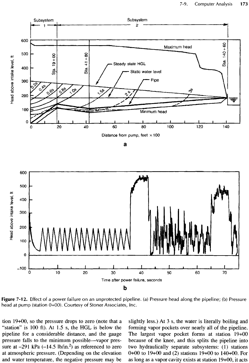
tion 19+00,
so the
pressure drops
to
zero (note that
a
"station"
is 100
ft).
At 1.5 s, the HGL is
below
the
pipeline
for a
considerable distance,
and the
gauge
pressure
falls
to the
minimum
possible
—
vapor
pres-
sure
at
-291
kPa
(-14.5
lb/in.
2
)
as
referenced
to
zero
at
atmospheric pressure. (Depending
on the
elevation
and
water temperature,
the
negative pressure
may be
slightly
less.)
At 3 s, the
water
is
literally boiling
and
forming
vapor pockets over nearly
all of the
pipeline.
The
largest vapor pocket
forms
at
station 19+00
because
of the
knee,
and
this splits
the
pipeline into
two
hydraulically separate subsystems:
(1)
stations
0+00
to
19+00
and (2)
stations 19+00
to
140+00.
For
as
long
as a
vapor cavity exists
at
station 19+00,
it
acts
Figure
7-12.
Effect
of a
power
failure
on an
unprotected
pipeline,
(a)
Pressure
head
along
the
pipeline;
(b)
Pressure
head
at
pump
(station
0+00).
Courtesy
of
Stoner Associates, Inc.
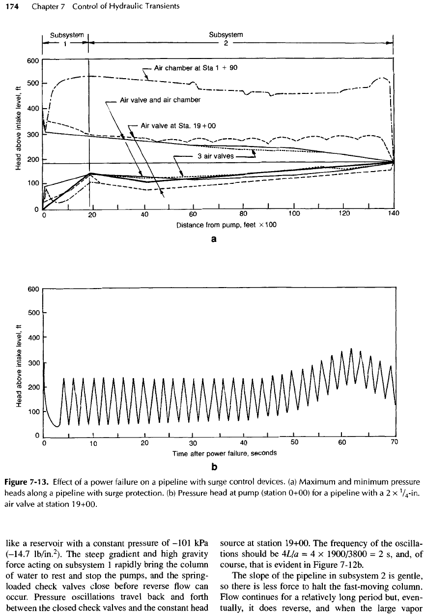
like
a
reservoir with
a
constant pressure
of
-101
kPa
(-14.7
lb/in.
2
).
The
steep gradient
and
high gravity
force
acting
on
subsystem
1
rapidly bring
the
column
of
water
to
rest
and
stop
the
pumps,
and the
spring-
loaded check valves close before reverse
flow can
occur. Pressure oscillations travel back
and
forth
between
the
closed check valves
and the
constant head
source
at
station 19+00.
The
frequency
of the
oscilla-
tions should
be
4L/a
= 4 x
1900/3800
= 2 s,
and,
of
course, that
is
evident
in
Figure
7-12b.
The
slope
of the
pipeline
in
subsystem
2 is
gentle,
so
there
is
less force
to
halt
the
fast-moving column.
Flow
continues
for a
relatively long period but, even-
tually,
it
does reverse,
and
when
the
large vapor
Figure
7-13.
Effect
of a
power failure
on a
pipeline
with
surge
control
devices,
(a)
Maximum
and
minimum
pressure
heads
along
a
pipeline
with
surge
protection,
(b)
Pressure
head
at
pump
(station
0+00)
for a
pipeline
with
a 2 x
V
4
-in.
air
valve
at
station
19+00.
pocket
at
station
19+00
collapses,
the
reverse
flow
suddenly
stops with
a
shock that
increases
the
head
to
about
550 ft for 7.5
s
—
the
time required
for a
wave
to
travel
to the
reservoir
and be
reflected back
at the
elastic speed
of
1160
m/s
(3800
ft/s) (see Figure
7-12b). Other vapor pockets also collapse
and
cause
a
jumble
of
peaks
in the
pressure trace.
The
energy gen-
erated
by the
vapor cavity collapse
is
large enough
to
create
a
rebound
effect
in
subsystem
2 and
open
another vapor cavity
at
station
19+00.
So,
about
65 s
after
power failure, there
is
another sudden jump
in
pressure caused
by the
collapse
of the new
vapor cav-
ity.
Cavities
may
open
and
close several more times
before
friction dissipates
the
energy.
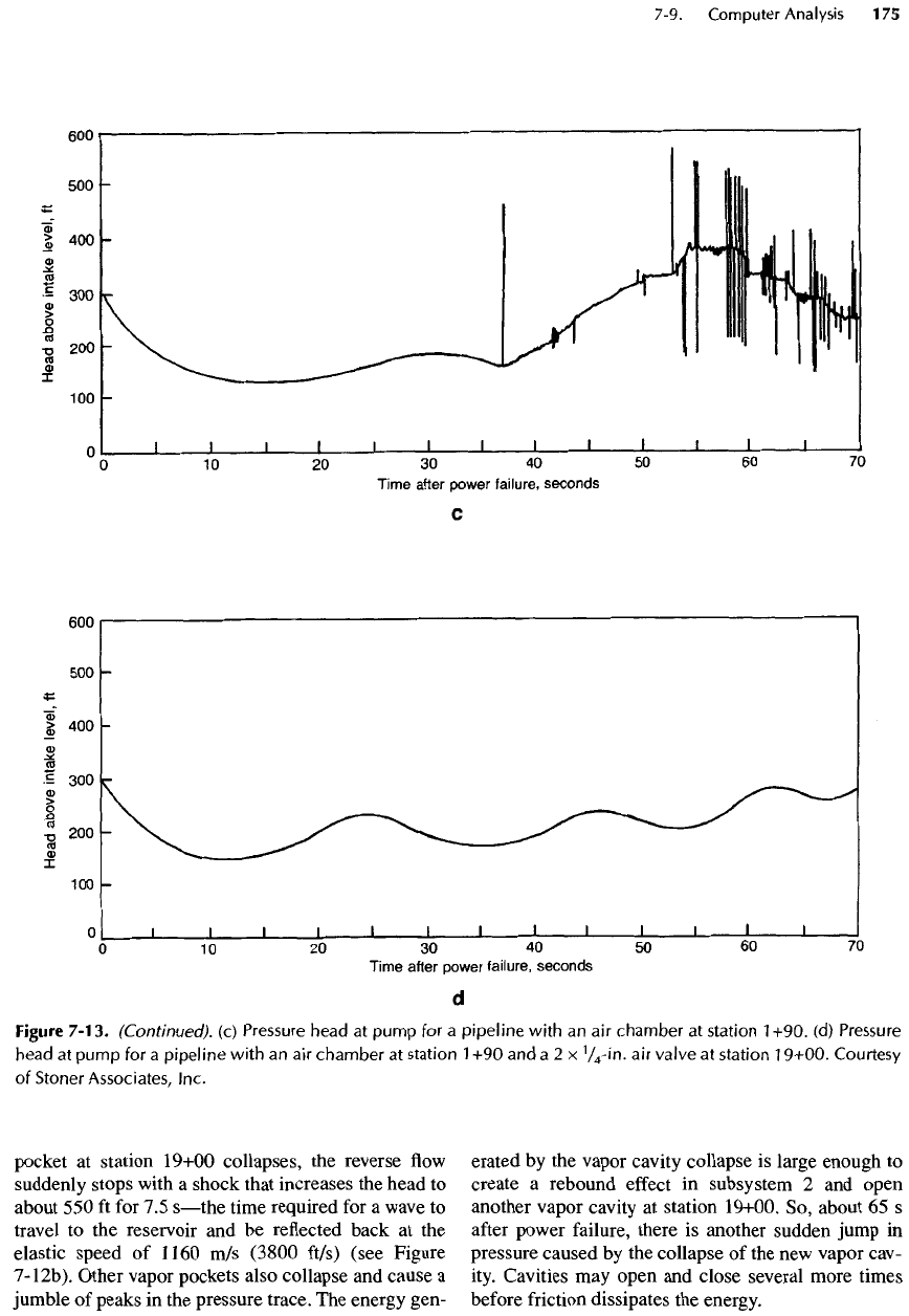
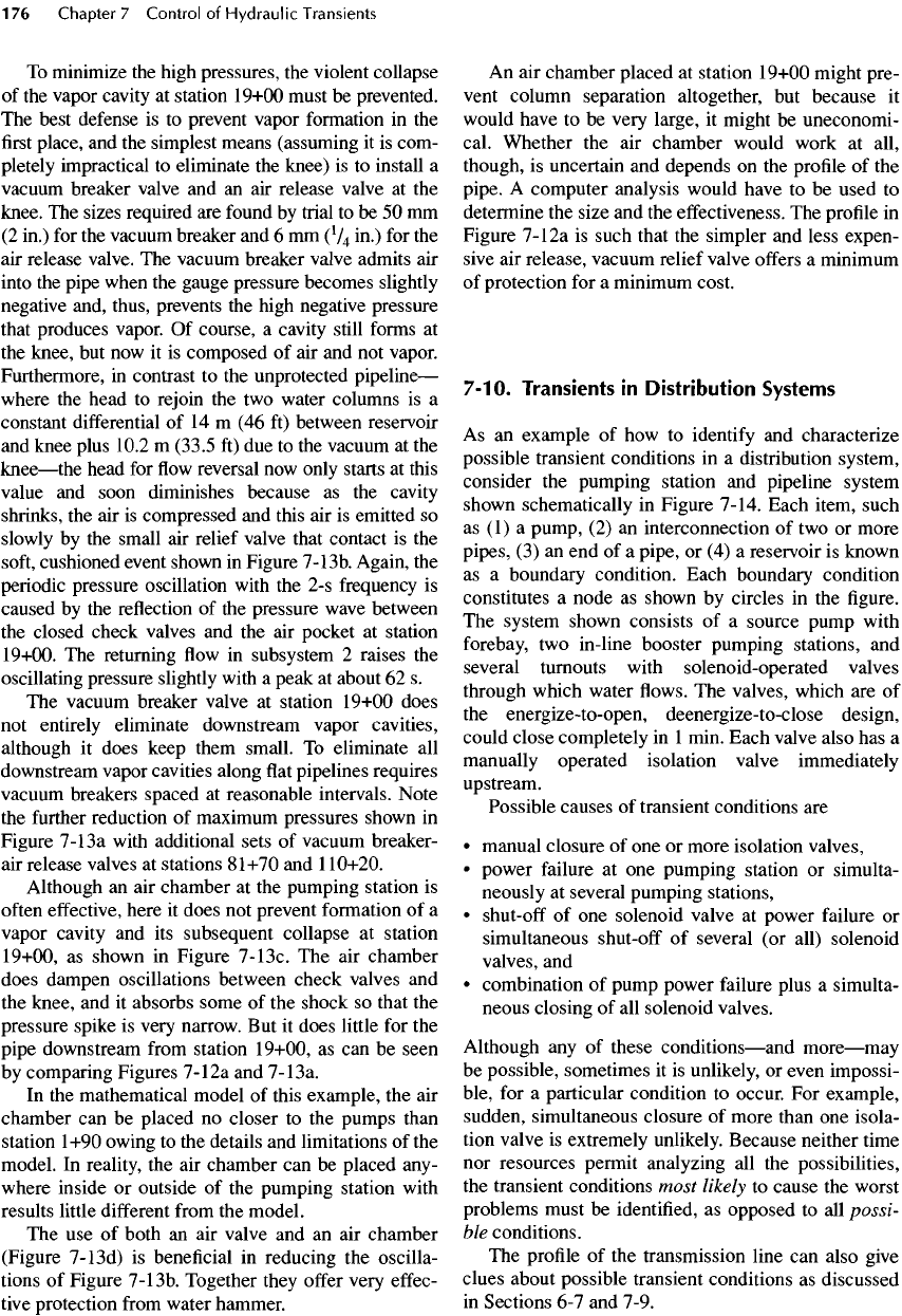
Figure
7-13.
(Continued),
(c)
Pressure
head
at
pump
for a
pipeline
with
an air
chamber
at
station
1+90.
(d)
Pressure
head
at
pump
for a
pipeline
with
an air
chamber
at
station
1 +90 and a 2 x
V
4
-in.
air
valve
at
station
19+00.
Courtesy
of
Stoner
Associates,
Inc.
To
minimize
the
high pressures,
the
violent collapse
of
the
vapor
cavity
at
station
19+00
must
be
prevented.
The
best defense
is to
prevent vapor formation
in the
first
place,
and the
simplest means (assuming
it is
com-
pletely impractical
to
eliminate
the
knee)
is to
install
a
vacuum
breaker valve
and an air
release valve
at the
knee.
The
sizes required
are
found
by
trial
to be 50 mm
(2
in.)
for the
vacuum breaker
and 6 mm
(
1
^
in.)
for the
air
release valve.
The
vacuum
breaker valve admits
air
into
the
pipe when
the
gauge pressure becomes slightly
negative
and, thus, prevents
the
high negative pressure
that
produces vapor.
Of
course,
a
cavity still
forms
at
the
knee,
but now it is
composed
of air and not
vapor.
Furthermore,
in
contrast
to the
unprotected
pipeline
—
where
the
head
to
rejoin
the two
water columns
is a
constant
differential
of 14 m (46 ft)
between reservoir
and
knee plus 10.2
m
(33.5
ft) due to the
vacuum
at the
knee
—
the
head
for flow
reversal
now
only starts
at
this
value
and
soon diminishes because
as the
cavity
shrinks,
the air is
compressed
and
this
air is
emitted
so
slowly
by the
small
air
relief valve that contact
is the
soft,
cushioned event shown
in
Figure
7-13b.
Again,
the
periodic pressure oscillation
with
the 2-s
frequency
is
caused
by the
reflection
of the
pressure wave between
the
closed check valves
and the air
pocket
at
station
19+00.
The
returning
flow in
subsystem
2
raises
the
oscillating pressure slightly
with
a
peak
at
about
62 s.
The
vacuum breaker valve
at
station 19+00 does
not
entirely eliminate downstream vapor cavities,
although
it
does
keep them small.
To
eliminate
all
downstream vapor cavities along
flat
pipelines requires
vacuum
breakers spaced
at
reasonable intervals. Note
the
further
reduction
of
maximum pressures shown
in
Figure
7-13a
with additional sets
of
vacuum breaker-
air
release valves
at
stations
81+70
and
1
10+20.
Although
an air
chamber
at the
pumping station
is
often
effective,
here
it
does
not
prevent formation
of a
vapor cavity
and its
subsequent collapse
at
station
19+00,
as
shown
in
Figure
7-13c.
The air
chamber
does dampen oscillations between check valves
and
the
knee,
and it
absorbs some
of the
shock
so
that
the
pressure spike
is
very narrow.
But it
does little
for the
pipe downstream
from
station 19+00,
as can be
seen
by
comparing Figures
7-12a
and
7-13a.
In
the
mathematical model
of
this example,
the air
chamber
can be
placed
no
closer
to the
pumps than
station
1+90 owing
to the
details
and
limitations
of the
model.
In
reality,
the air
chamber
can be
placed any-
where
inside
or
outside
of the
pumping station with
results
little
different
from
the
model.
The use of
both
an air
valve
and an air
chamber
(Figure
7-
13d)
is
beneficial
in
reducing
the
oscilla-
tions
of
Figure
7-13b.
Together they
offer
very
effec-
tive
protection
from
water hammer.
An
air
chamber placed
at
station
19+00
might pre-
vent
column separation altogether,
but
because
it
would have
to be
very large,
it
might
be
uneconomi-
cal. Whether
the air
chamber would work
at
all,
though,
is
uncertain
and
depends
on the
profile
of the
pipe.
A
computer analysis would have
to be
used
to
determine
the
size
and the
effectiveness.
The
profile
in
Figure
7-12a
is
such that
the
simpler
and
less expen-
sive
air
release, vacuum relief valve
offers
a
minimum
of
protection
for a
minimum cost.
7-10.
Transients
in
Distribution
Systems
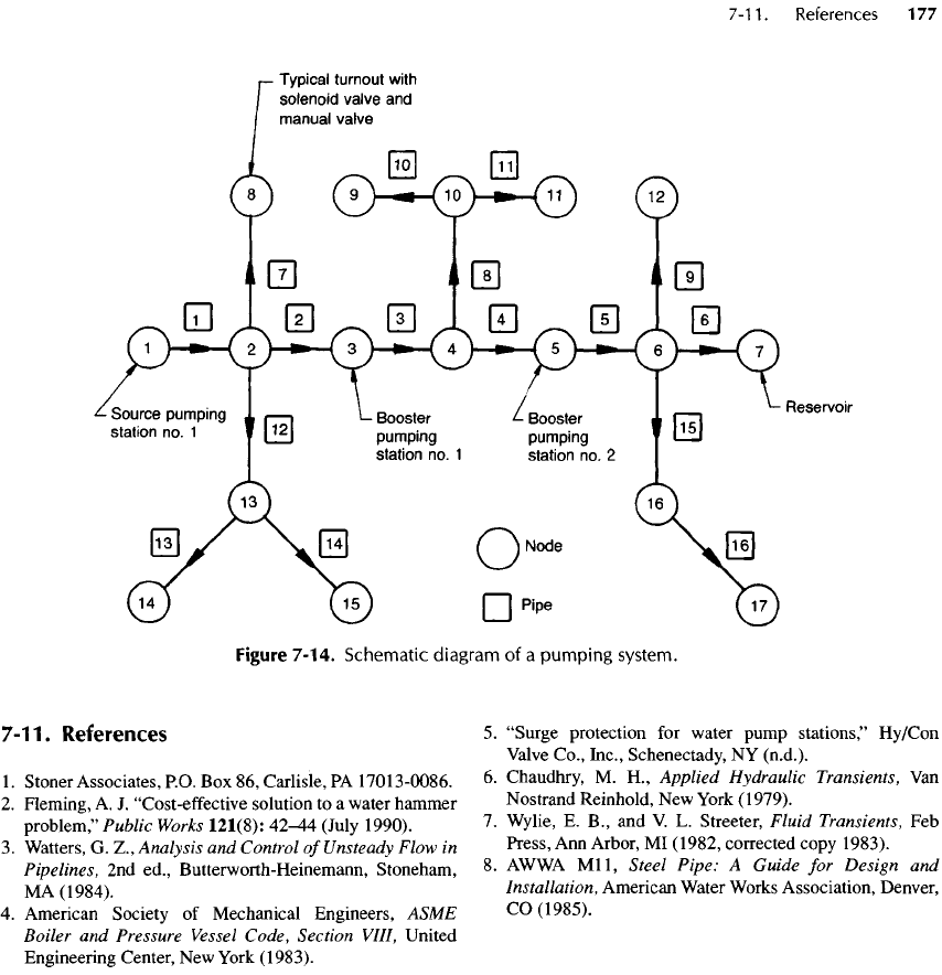
As an
example
of how to
identify
and
characterize
possible transient conditions
in a
distribution system,
consider
the
pumping station
and
pipeline system
shown
schematically
in
Figure 7-14. Each item, such
as (1) a
pump,
(2) an
interconnection
of two or
more
pipes,
(3) an end of a
pipe,
or (4) a
reservoir
is
known
as
a
boundary condition. Each boundary condition
constitutes
a
node
as
shown
by
circles
in the figure.
The
system shown consists
of a
source pump with
forebay,
two
in-line booster pumping stations,
and
several turnouts with solenoid-operated valves
through
which water
flows. The
valves, which
are of
the
energize-to-open,
deenergize-to-close
design,
could
close
completely
in 1
min.
Each valve also
has a
manually
operated isolation valve immediately
upstream.
Possible causes
of
transient conditions
are
•
manual closure
of one or
more
isolation
valves,
•
power
failure
at one
pumping station
or
simulta-
neously
at
several pumping stations,
•
shut-off
of one
solenoid valve
at
power
failure
or
simultaneous
shut-off
of
several
(or
all) solenoid
valves,
and
•
combination
of
pump power
failure
plus
a
simulta-
neous closing
of all
solenoid valves.
Although
any of
these
conditions
—
and
more
—
may
be
possible, sometimes
it is
unlikely,
or
even impossi-
ble,
for a
particular condition
to
occur.
For
example,
sudden, simultaneous closure
of
more than
one
isola-
tion valve
is
extremely unlikely. Because neither time
nor
resources permit analyzing
all the
possibilities,
the
transient conditions most
likely
to
cause
the
worst
problems must
be
identified,
as
opposed
to all
possi-
ble
conditions.
The
profile
of the
transmission
line
can
also
give
clues about possible transient conditions
as
discussed
in
Sections
6-7 and
7-9.
7-11.
References
1.
Stoner Associates,
RO. Box 86,
Carlisle,
PA
17013-0086.
2.
Fleming,
A. J.
"Cost-effective solution
to a
water hammer
problem," Public
Works
121(8):
42^4
(July 1990).
3.
Watters,
G.
Z.,
Analysis
and
Control
of
Unsteady
Flow
in
Pipelines,
2nd
ed.,
Butterworth-Heinemann,
Stoneham,
MA
(1984).
4.
American Society
of
Mechanical Engineers, ASME
Boiler
and
Pressure
Vessel
Code, Section
VHI,
United
Engineering Center,
New
York (1983).
5.
"Surge
protection
for
water pump
stations,"
Hy/Con
Valve
Co., Inc., Schenectady,
NY
(n.d.).
6.
Chaudhry,
M.
H.,
Applied Hydraulic Transients,
Van
Nostrand Reinhold,
New
York
(1979).
7.
Wylie,
E.
B.,
and V. L.
Streeter, Fluid Transients,
Feb
Press,
Ann
Arbor,
MI
(1982,
corrected
copy 1983).
8.
AWWA
Mil,
Steel Pipe:
A
Guide
for
Design
and
Installation, American Water Works Association, Denver,
CO
(1985).
Figure
7-14. Schematic diagram
of a
pumping
system.
This chapter
is
intended primarily
for
those project
managers
who
have limited knowledge
of
electrical
fundamentals
but
must nevertheless develop rapport
and
communication skills
with
electrical designers.
The
fundamentals
of
elementary
electrical
theory
are
reviewed
in
Section 8-2, power
and
control systems
in
Section 8-3, generators
in
Section 8-4, grounding
and
ground
fault
projection
in
Section 8-5, lighting, power
outlets
in
Section 8-6, circuit diagrams
in
Section 8-7,
and
power
and
control system practice
in
Section 8-8.
Although design
principles
are
given
herein,
design
per se is
covered
in
Chapter
9.
References
to
books
are
given
in
standard
form,
but
references
to
specifications, standards,
and
codes
are
given
in
abbreviated
form,
such
as NEC
(for
National
Electrical
Code)
or
NFPA
78
(for National
Fire Protection Association Lightning Protection
Code). Titles
of
codes
and
standards
are
given
in
Appendix
E and
publishers' addresses
are
given
in
Appendix
F.
Project
engineers should realize that
all
electrical
design
must
be
done
or
supervised
by a
professional
Chapter
8
Electrical
Fundamentals
and
Power
System
Principles
STANLEYS.
HONG
PHILIPA.
HUFF
PAUL
C.
LEACH
CONTRIBUTORS
Roberts.
Benfell
Mayo
Gottliebson
Stephen
H.
Palac
Evans
W.
Paschal
Richard
N.
Skeehan
Patricia
A.
Trager
electrical
engineer
who is
licensed
in the
state where
the
project
is
located.
All
work should
be
checked
by
another
qualified
electrical engineer. Furthermore,
project
engineers must
be
reasonably familiar with:
•
Electrical codes
•
Definitions
(see Section 8-1, Chapter
2, and
NEC)
•
Electrical symbols (see Tables
2-5 and
2-6)
•
Single line diagrams (see Section 8-7)
•
Power
and
control system elements
and
practices
(see
Section
8-8)
•
State
and
federal regulations pertaining
to
energy
conservation
—
especially
lighting
•
Requirements
of the
local building
codes
• EPA
design guidelines.
8-1
.
Definitions
and
Code
References
Refer
to the
latest revision
of the NEC and
ANSI/
IEEE
100 for
definitions
of
electrical terms.
See
also
Section
2-2
and,
for
voltage terminology, Section 8-8.

The
following
are
some commonly used terms
in
pumping
station design.
The
sources
of
quoted
defini-
tions
are
given
in
brackets.
Ampacity:
The
current
in
amperes that
a
conductor
can
carry continuously under
the
conditions
of use
without
exceeding
its
temperature rating
[NEC].
Branch
circuit:
The
circuit conductors between
the
final
overcurrent
device protecting
the
circuit
and
the
outlet(s)
and the
utilization equipment such
as
motors, lights, etc.
[NEC].
Circuit breaker:
A
device designed
to
open
and
close
a
circuit
by
nonautomatic means
and to
open
the
circuit automatically
on a
predetermined overcur-
rent
without damage
to
itself.
Continuous load:
A
load
in
which
the
maximum cur-
rent
is
expected
to
continue
for
three hours
or
more
[NEC].
Controller:
A
device
or
group
of
devices that governs
the
electrical
power delivered
to the
utilization
equipment
in a
predetermined manner.
A
motor
controller includes
any
device, such
as a
switch
or
contactor, normally used
to
start
and
stop
a
motor
and
may
include equipment (such
as a
reactor,
resistor,
or
solid-state system) that limits motor
starting
current [based
on
NEC].
Current withstand rating:
The
maximum allowable
current,
either instantaneous
or for a
specified
period
of
time, that
a
device
can
withstand without
damage [ANSI
10O].
Fault:
An
unintended connection
(a
short circuit)
between phases
or
between
a
phase
and
ground.
A
fault
may
result
in an
excessive current
in the
faulted
equipment,
in its
supply conductors,
and in
the
supply system itself.
Feeder:
All
circuit conductors between
the
service
equipment
or the
source
of a
separately derived sys-
tem
and the final
branch circuit overcurrent device
[NEC].
Frequency:
The
number
of
periods
(or
cycles)
per
unit
time.
Hertz:
The
unit
of
frequency
in
cycles
per
second,
abbreviated
Hz.
Motor
control center
(MCC):
An
assembly
of
grouped control equipment used primarily
for
con-
trol
of
motors
and
associated power distribution
applications.
Overcurrent:
Any
current
in
excess
of the
rated cur-
rent
of
equipment
or the
ampacity
of a
conductor.
Overcurrent
may
result
from
overload, short circuit,
or
ground
fault
[NEC].
Overload:
Operation
of
equipment
in
excess
of the
normal
full-load
rating
(or of a
conductor
in
excess
of
rated ampacity) that would cause damage
or
dan-
gerous overheating when
it
persists
for a
sufficient
length
of
time.
A
fault,
such
as a
short circuit
or a
ground
fault,
is not an
overload
[NEC].
Power
factor:
The
cosine
of the
angle
by
which
the
current
lags (due
to
inductance)
or
leads (due
to
capacitance)
the
voltage.
Service:
The
conductors
and
equipment
for
deliver-
ing
electrical energy
from
the
supply system (usu-
ally
an
electric utility)
to the
wiring system
of the
premises served [based
on
NEC].
Switching apparatus:
A
device
for
opening
and
clos-
ing or for
changing
the
connections
of a
circuit.
It
includes
switches,
fuses,
circuit breakers,
and
con-
tactors
[ANSI/IEEE
Std
141-1986
Art
9.2].
8-2.
Electrical
Fundamentals
Electricity (the movement
of
electrons)
flows
easily
in
conductors such
as
copper
and
hardly
at all in
insula-
tors
such
as
rubber
or
glass. Electrons
flow in the
cir-
cuit
conductors
from
the
negative pole
to the
positive
pole
of a
battery,
but by
custom,
electrical
current
is
said
to flow
from
the
positive
to
negative pole.
In
semiconducting
media
and in
electrolytes both posi-
tive
and
negative charges
flow to
their respective
attracting
terminals.
Electricity
flows
when
a
voltage source providing
electrical pressure
(or
force)
to the
electrons
is in
series
with
a
complete
circuit.
Ordinarily,
a
complete
circuit
consists
of the
voltage source, conductors,
and
a
load that transforms
the
electrical energy
from
the
source into usable energy such
as
heat
or
mechanical
work.
A
switch provides
the
means
of
making
and
breaking
a
circuit intentionally and, thus, controls
the
flow
of
electricity.
If the
circuit
is
broken
at any
point,
electricity does
not flow.
Electrical pressure (voltage)
can be
produced
by:
(1)
chemical reactions
(as in
batteries),
(2)
movement
of
magnets near coils
(as in
generators),
(3)
contact
between dissimilar metals (thermocouples,
for
exam-
ple),
(4)
friction
(lightning,
for
example),
or (5)
light
energy impinging upon
a
thin semiconducting
film (as
in
photovoltaic systems
or
solar cells).
Alternating
current (ac) power
is the
most common,
because
it is
easy
to
generate, transform
(from
one
voltage
level
to
another),
and
utilize.
It is
commonly
available
as
single phase
or
three phase. Direct current
(dc)
is
often
used
to
power emergency lights
and to
provide control power
in
large systems.
It is
used
to
start
engine generator sets,
to
power
dc
pump motors
in
adjustable-speed applications,
and as field
supply
to
synchronous motors
and
generators.
But dc is not
available
from
utilities.
It
must
be
produced
on
site.

The
potential
difference
(the electrical equivalent
of
pressure) between
any two
points
in an
electric
sys-
tem is
measured
in
volts (V).
The
unit
of
quantity
of
electrical charge
is the
coulomb (C).
The
ampere
(A)
is the
measure
of the
rate
at
which charges move past
a
given point
in
coulombs
per
second.
The
energy
or
work
required
to
move
one
coulomb through
a
poten-
tial
difference
of one
volt
is the
joule
(J) and the
rate
of
expenditure
of
energy
is
measured
in
joules
per
sec-
ond or
watts
(W).
In an
alternating current system,
an
ampere
of
alternating
current
is
defined
as the
measured value
that
causes
the
same heating
effect
as one
ampere
of
direct current.
The
ampere
is
mathematically equal
to
0.707
times
the
peak value
of a
sinusoidal alternating
waveform,
and it is
sometimes referred
to as the
root-
mean-square (RMS) value.
The
measure
of the
opposition
or
resistance
to the
flow
of
electrical current
is the ohm
(Q).
In dc
circuits
and
in
unity power factor
ac
circuits,
one
volt
of
potential
difference
is
required
to
cause
a
current
of
one
ampere
to flow
through
a
resistance
of one
ohm
—
a
relation known
as
Ohm's law.
/ =
V/R
(8-1)
where
/ is
current
in
amperes,
V is
volts,
and R is
resistance
in
ohms.
In dc
circuits,
the
average values
for
current
and
voltage
are
used.
In ac
circuits with
sinusoidal
waveforms,
RMS
(root-mean-square) val-
ues are
used
for
current
and
voltage.
Electrical power
in dc and
unity
power factor
ac
circuits
is the
product
of
current
and
voltage.
P
= VI
(8-2)
where
P is
power
is
watts.
In ac
circuits with
a
power
factor
that
is not
unity,
the
above relation becomes
more complex (Equation 8-3). Nevertheless, power
is
equal
to the
product
of
resistance
and the
square
of the
RMS
value
of
current. Power usage
at the
rate
of one
watt
for a
period
of one
hour
is
termed
one
watt-hour
(or
3600
J) of
electrical energy.
Generation
of
Electricity
An
electrical source
as
described
in the
foregoing dis-
cussion
generates
a
potential
difference
called
"volt-
age."
The
voltage
may be
steady, pulsing (with
constant
polarity),
or
alternating
in
polarity.
A
battery
generates
a
steady
dc
voltage,
as do
other static
sources
such
as
photovoltaic
cells
and
thermocouples.
An
ac
generator produces
an
alternating voltage with
a
sinusoidal waveform.
A dc
generator
is an ac
gener-
ator with either:
(1)
solid-state
rectifiers
or (2) a
com-
mutator that switches connections
to
coils
on the
rotating armature
and
thereby produces
a
pulsating
dc
voltage.
The
movement
of the bar
magnet across
the
coil
of
wire
in
Figure
8-1
generates voltage
because
lines
of
magnetic force
or flux
move across
the
coil. Reversing
the
direction
of
movement reverses
the
voltage polar-
ity,
as
from
positive
to
negative. Alternatively,
if the
polarity
of the
magnet
is
reversed,
the
voltage polarity
reverses.
By
rotating
the
magnet
as
shown
in
Figure
8-2
the
voltage alternately reverses
as the
north
and
south
poles
of the
magnet pass
the
coil.
The
voltage
is
produced
as a
sine wave, which
is
complete with
one
revolution
of the
magnet.
If the
magnet revolves
at 60
revolutions
per
second,
the
voltage
is
produced
at 60
Hz. Two
magnets arranged with alternating polarity
Figure
8-1.
Producing
potential
(voltage)
with
a
moving
magnet.
Figure
8-2.
A
simple
ac
generator,
(a)
Voltmeter
and
rotating
magnet;
(b)
voltage
produced.
