Pump Handbook by Igor J. Karassik, Joseph P. Messina, Paul Cooper, Charles C. Heald - 3rd edition
Подождите немного. Документ загружается.

2.446 CHAPTER 2
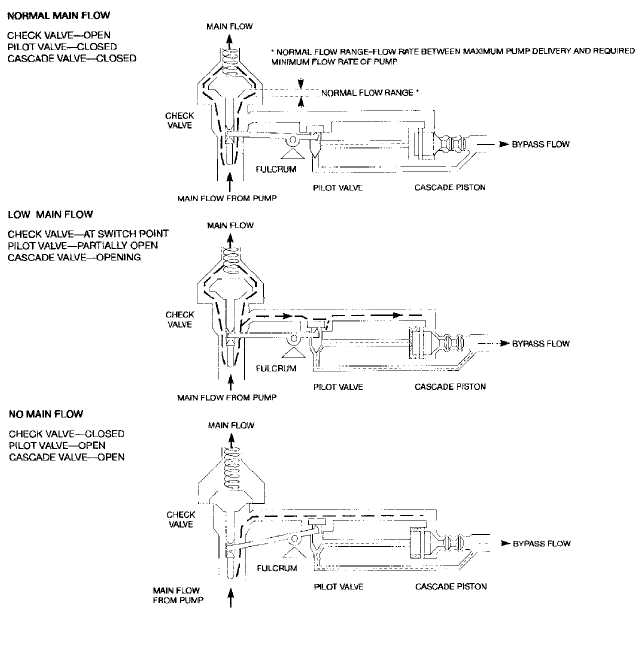
FIGURE 9 Operation of a typical pilot-operated ARC bypass valve actuated through a lever mechanism
Head This requires only an accurate pressure switch, set for a discharge pressure cor-
responding to the total pump head when the pump is close to the shutoff capacity. For con-
servative results, calculate based on minimum suction pressure. To use this method, the
pump characteristic must rise continuously to shutoff. Control circuitry may require
delays to reject spurious pressure surges.
Temperature A temperature sensor mounted on the pump casing or in the discharge
and close to the pump can signal for a shutdown of all or some of the operating pumps.
The trip can be on either a high temperature sensing or a high differential temperature
sensing between inlet and discharge.This method can protect against large temperature
rises (occurring at perhaps 5% or less of capacity) but is less sensitive to smaller rises at
higher percentages of capacity where adverse hydraulic effects begin for large and high-
power pumps.
Low-Flow Systems These protection systems can be configured in various ways.A low-
flow switch can trip the pump off at a predetermined setpoint. A flow meter can signal a
controller to shut down the pump. If this protection circuit is installed, the pump start cir-
cuit must temporarily bypass this trip in order to start the pump.This is normally accom-
plished by a spring-loaded switch that bypasses the low-flow trip when held in the “Start”
position, but activates the trip protection in the “Run” position.

2.3.4 CENTRIFUGAL PUMP MINIMUM FLOW CONTROL SYSTEMS 2.447
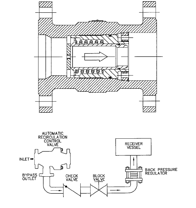
FIGURE 10 Pilot operated multistage bypass trim actuated by an in-line pilot valve
FIGURE 11 Typical in-line serviceable ARC valve
2.448 CHAPTER 2
OTHER BYPASS SYSTEM HARDWARE __________________________________
Orifices
In high pressure applications, the system often does not provide adequate pres-
sure in the bypass line to prevent cavitation or flashing. Either of these conditions is unde-
sirable because it can cause damage to both valves and the pipe system or cause a reduction
in flow below the minimum desired, jeopardizing the pump protection system. All pressure-
reducing valves will experience a velocity-induced recovery effect that will limit the amount
of pressure drop a valve can take and cause a reduction in flow capacity.
The requirement of backpressure is generic to all pressure-reducing applications. Pres-
sure reduction even by multiple stage cascading can minimize the requirement; however,
no valve design will redefine a fluid’s physical properties. This becomes especially impor-
tant in modulating systems. A fixed orifice will not provide the proper backpressure at all
flow levels.
As the flow in the bypass line is reduced, the orifice becomes less effective. Proper sys-
tem design should be used to optimize valve pressure reduction and consider all fluid
dynamic effects downstream of any pressure-reducing device. When adequate backpres-
sure is not available downstream of a pressure reducing valve, vapor bubbles will form in
the zone just downstream of the valve last stage control surface.This zone is defined as the
“Vena Contracta” and represents the point of highest fluid velocity and lowest pressure.
The potential for 1) damage to downstream piping components and 2) flow reduction
exists from this point. When line pressure remains below the fluid vapor pressure, any
existing bubbles will remain and expand as piping friction further reduces line pressure.
This can be defined as “flashing condition” and is characterized by a polished appearance
on affected surfaces.When the line pressure drops below the fluid vapor pressure and then
recovers, any entrapped vapor bubbles will collapse (implode). This is defined as a “cavi-
tating condition” and is characterized by a cinder-like appearance on affected surfaces. The
resolution of either condition is best addressed by eliminating vapor formation. This can
be assured by the provision of adequate back pressure through the use of a fixed or vari-
able orifice.
Fixed Orifice Simple, easily replaced orifices that reduce the pressure are an effective
way to reduce bypass head and provide adequate backpressure in bypass systems. Sev-
eral stages may be necessary, however, to break down high-pressure drops without flash-
ing. For calculations of flow through standard-shaped orifices, see Section 8.1 and 8.2.
Coefficients of discharge for oddly shaped multistage orifices are difficult to calculate.
However, manufacturers of these specialties can furnish curves of delivery as a function of
pressure.
Variable Orifice In modulating systems, a fixed orifice will not provide the proper back-
pressure over a wide flow range. A backpressure regulator (BPR) has a variable orifice
with a spring-loaded plunger that is designed to open at a specified differential pressure.
If flow and differential pressure increase, it opens further to maintain the differential
pressure and backpressure constant. Figure 12 illustrates a typical BPR construction. Fig-
ure 13 shows a standard BPR installation. The BPR is normally located as close to the
receiver vessel as possible so that the correct backpressure is maintained in the entire
bypass line.
Valves, Piping, and Fittings For cold water at low pressure, a simple power-actuated
globe-type bypass valve is often adequate. In modulating bypass systems, the bypass
valve must resist throttling damage, particularly if the water is hot. Staging the pressure
drop in the valve is the most common way to reduce or eliminate flashing and cavitation
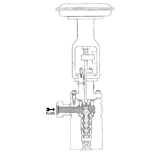
damage to the valve trim or body. Figure 14 illustrates a typical multi-stage pressure
reducing valve (PRV).
Pressure is reduced in stages to ensure that the pressure never decreases below the
fluid vapor pressure. This prevents cavitation and the resultant valve damage and noise.
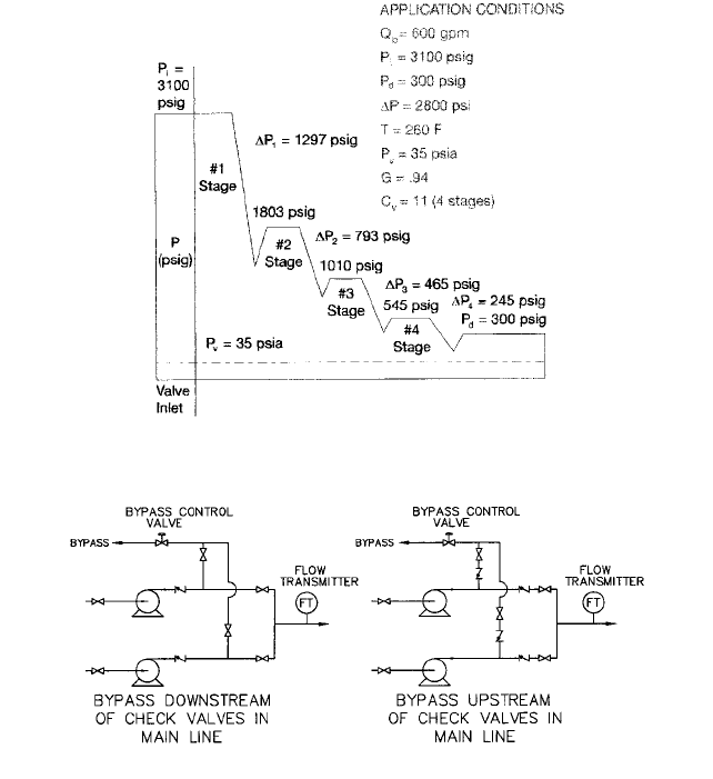
Figure 15 illustrates typical calculations for reducing pressure in sequential stages. Refer
to Chapter 7 for detailed information regarding valve sizing and selection.
2.3.4 CENTRIFUGAL PUMP MINIMUM FLOW CONTROL SYSTEMS 2.449
FIGURE 12 Construction of a typical backpressure regulator
FIGURE 13 Backpressure regulator installation
Pipe material like that used for the main discharge is adequate for nearly all of the
bypass line. Near the orifice and control valve outlets, however, heavier wall or higher
chrome content will lengthen life.Welded piping is common for high pressures.To prevent
erosion, pipe fittings (especially elbows) should not immediately follow an orifice.
Flow Meters Flow rate is the variable that must be measured for most automatic bypass
multi-component control systems. The meter may have any type of primary element that
will produce an accurate signal at the process flow for which the bypass must be controlled.
A simple orifice meter or venturi tube is commonly used. The user must have the
required straight upstream and downstream pipe lengths or use flow straighteners to
obtain an accurate reading. The device must be properly sized to provide both accurate
indication at relatively low process flows and satisfactory pressure drop at maximum
process flow conditions.
Flow meters can be located either upstream or downstream of the pump. Meters
located upstream are at lower internal pressure but are larger in diameter with larger
flanges. In addition, pressure drop at rated flow is important to avoid low pump NPSH.
Meters located downstream are normally smaller but must be rated for the maximum
pump discharge pressure.
2.450 CHAPTER 2
FIGURE 14 Construction of a typical multistage pressure-reducing valve
Controls Controls range in complexity from a simple pressure switch that stops a pump
drive motor to modulating systems that meter flow and maintain a selected minimum flow
through the pump. The control system may have to provide a deadband near the opening
point and be sufficiently stable to hold bypass flow nearly constant in spite of erratic flow
during upsets and startup.
For example, when the primary flow-measuring element is upstream of the bypass
branch off, sufficient decease in flow will cause the bypass control to open in an “On-Off”
bypass system. The main control valve, farther downstream, will then also open to main-
tain flow to the boiler or process. The primary element will sense the added flow and, in a
simple bypass control system, close the bypass valve, initiating hunting in flow and valve
action. To prevent this, the setpoint for bypass valve closing must be greater than twice the
minimum bypass flow. If minimum flow is in the 30–50% range, this wastes energy dur-
ing bypass. This control problem is avoided if a modulating system is installed.
SPECIAL BYPASS SYSTEMS___________________________________________
Pumps in Parallel
It is possible to provide a single bypass valve for two or more pumps,
as shown in Figure 16. The bypass line and valve must be able to handle simultaneously
2.3.4 CENTRIFUGAL PUMP MINIMUM FLOW CONTROL SYSTEMS 2.451
FIGURE 15 Calculations for pressure reduction through a multistage valve
FIGURE 16 Examples of a single bypass valve that provides minimum flow control for two parallel pumps
the total bypass flow of all pumps. The pumps must operate together and they must have
identical head-capacity curves. If they do not, the bypass flow will differ between pumps.
The pump with the lower head may have insufficient bypass flow or could be completely
shut off.
In the system of Figure 16 (left), the main line check valve prevents backflow through
an idle pump. If the branch off were installed as shown in Figure 16 (right), an additional
check valve in each bypass connection would be necessary to stop the backflow. Therefore,
this latter configuration is not recommended.
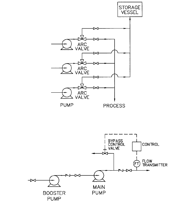
An alternative arrangement that provides better operational flexibility and pump pro-
tection is illustrated in Figure 17. Each pump is individually protected by its own auto-
matic recirculation control (ARC) valve. Pumps can be operated individually or in any
combination and the pump head characteristic curves do not have to be identical.
Pumps in Series A single bypass line and valve can protect two pumps in series (see
Figure 18). The designer must provide for the larger of the two separately evaluated
bypass flows and must take into account the heating effect of the upstream pump. The
pumps cannot operate singly unless additional piping and controls are installed.
2.452 CHAPTER 2
FIGURE 17 Multiple parallel pumps individually protected by ARC valves
FIGURE 18 Example of a single bypass line that protects two pumps in series
VARIABLE SPEED PUMP BYPASS CONSIDERATIONS______________________
Large horsepower pumps are often powered by steam turbines or with motors connected
through a variable speed coupling. The effect of decreased speed and discharge head is to
reduce the minimum flow requirement for the pump. Therefore, if the minimum required
bypass flow is calculated and sized with the pump at normal operating speed and pres-
sure, the bypass flow will be adequate when the pump is operated at lower speeds.
Warning If a constant backpressure device such as a backpressure regulator is used to
control bypass pressure, precautions must be taken to ensure that the pump is never oper-
ated at pressures below the BPR setting. If the pump is operated below the BPR setting,
the pump will have no bypass flow and may be damaged in a short time.
In a typical boiler system, a constant speed booster pump, requiring less minimum flow
than the boiler-feed pump, could be protected by the bypass flow for the variable speed
boiler feed pump. The designer must determine if the booster pump bypass flow is suffi-
cient when the high pressure feed pump is running at minimum discharge pressure.
2.3.4 CENTRIFUGAL PUMP MINIMUM FLOW CONTROL SYSTEMS 2.453
REFERENCES _______________________________________________________
1. Dufour, J. W., and W. E. Nelson. Centrifugal Pump Source Book. McGraw-Hill, 1992.
2. Garay, P. N. Pump Application Desk Book. 2nd ed. Fairmount Press, 1992.
3. Anderson, H. H. Centrifugal Pumps and Allied Machinery. 4th ed. Elsevier Science
Publishers Ltd., 1994.
4. Heald, C. C. “Cameron Hydraulic Data.” 18th ed. Ingersoll-Dresser Pump Company,
now Flowserve Corporation, 1995.

IGOR J. KARASSIK
C. J. TULLO
2.455
SECTION 2.4
CENTRIFUGAL PUMP
PRIMING
A centrifugal pump is primed when the passageways of the pump are filled with the liq-
uid to be pumped. The liquid replaces the air, gas, or vapor in the passageways. This may
be done manually or automatically.
When a pump is first put into service, its passageways are filled with air. If the suction
supply is above atmospheric pressure, this air will be trapped in the pump and compressed
somewhat when the suction valve is opened. Priming is accomplished by venting the
entrapped air out of the pump through a valve provided for this purpose.
Unlike a positive displacement pump, a centrifugal pump that takes its suction from
a supply located below the pump, which is under atmospheric pressure, cannot start and
prime itself (unless designed to be self-priming, as described later in this section). At its
rated capacity, a positive displacement pump will develop the necessary pressure to
exhaust air from its chambers and from the suction piping. Centrifugal pumps can also
pump air at their rated capacity, but only at a pressure equivalent to the rated head of the
pump. Because the specific weight of air is approximately that of water, a centrifugal
pump can produce only of its rated liquid pressure. For every 1 ft (1 m) water has to
be raised to prime a pump, the pump must produce a discharge head of air of approxi-
mately 800 ft (m). It is therefore apparent that the head required for a conventional cen-
trifugal pump to be self-priming and to lift a large column of liquid (and in some cases to
discharge against an additional static liquid head) when pumping air is considerably
greater than the rating of the pump. Centrifugal pumps that operate with a suction lift
can be primed by providing (1) a foot valve in the suction line, (2) a single-chamber prim-
ing tank in the suction line or a two-chamber priming tank in the suction and discharge
lines, (3) a priming inductor at the inlet of the suction line, or (4) some form of vacuum-
producing device.
1
800
1
800

2.456 CHAPTER TWO
FIGURE 1 Single-chamber priming tank
FOOT VALVES _______________________________________________________
A foot valve is a form of check valve installed at the bottom, or foot, of a suction line. When
the pump stops and the ports of the foot valve close, the liquid cannot drain back to the
suction well if the valve seats tightly. Foot valves were very commonly used in early instal-
lations of centrifugal pumps. Except for certain applications, their use is now much less
common.
A foot valve does not always seat tightly, and the pump occasionally loses its prime.
However, the rate of leakage is generally small, and it is possible to restore the pump to
service by filling and starting it promptly. This tendency to malfunction is increased if the
liquid contains small particles of foreign matter, such as sand, and foot valves should not
be used for such service. Another disadvantage of foot valves is their unusually high fric-
tional loss.
The pump can be filled through a funnel attached to the priming connection or from an
overhead tank or any other source of liquid. If a check valve is used on the pump and the
discharge line remains full of liquid, a small bypass around the valve permits the liquid in
the discharge line to be used for repriming the pump when the foot valve has leaked. Pro-
vision must be made for filling all the passageways and for venting out the air.
PRIMING CHAMBERS _________________________________________________
The Single-Chamber Tank
A single-chamber primer is a tank with a bottom outlet that
is level with the pump suction nozzle and directly connected to it. An inlet at the top of
the tank connects with the suction line (Figure 1). The size of the tank must be such that
the volume contained between the top of the outlet and the bottom of the inlet is approx-
imately three times the volume of the suction pipe. When the pump is shut down, the liq-
uid in the suction line may leak out, but the liquid in the tank below the suction inlet
cannot run back to the supply. When the pump is started, it will pump this entrapped liq-
uid out of the priming chamber, creating a vacuum in the tank.The atmospheric pressure
on the supply will force the liquid up the suction line into the priming chamber.