Pump Handbook by Igor J. Karassik, Joseph P. Messina, Paul Cooper, Charles C. Heald - 3rd edition
Подождите немного. Документ загружается.

2.4 CENTRIFUGAL PUMP PRIMING 2.467
GENERAL___________________________________________________________
Because a great number of automatic priming devices and systems are available, care
should be taken to use the type or variation best suited to the application. The discussion
of priming in this section does not, of course, cover all makes and modifications available
for every specific application.
An automatic priming system will often allow units to be operated with excessive air
leakage into the suction lines.This is poor practice because it requires the operation of the
vacuum producer for greater periods of time than normally necessary.
FURTHER READING __________________________________________________
Apco/Valve and Primer Corp. Automatic Pump Primers, Technical Bulletin 721, Schaum-
burg, IL, 1978.
Hrivnak, S. J. “Why Doesn’t Your Self-Priming Pump Work?” Pumps and Systems Maga-
zine, June, 1999.
Karassik, I. J., and Carter, R. Chap. 21 in Centrifugal Pumps: Selection, Operation, and
Maintenance. McGraw-Hill: New York, 1960.

Displacement
Pumps
C•H•A•P•T•E•R•3

WILLIAM K. CHAPLIS
FREDERIC W. BUSE
3.3
SECTION 3.1
POWER PUMP THEORY
A power pump is a positive displacement machine consisting of one or more cylinders, each
containing a piston or plunger. The pistons or plungers are driven through slider-crank
mechanisms and a crankshaft from an external source. The capacity of a given pump is
governed by the rotational speed of the crankshaft.
Unlike a centrifugal pump, a power pump does not develop pressure; it only produces a
flow of fluid. The downstream process or piping system produces a resistance to this flow,
thereby generating pressure in the piping system and discharge portion of the pump. The
flow fluctuates at a rate proportional to the pump speed and number of cylinders. The
amplitude of the fluctuations is a function of the number of cylinders. In general, the greater
the number of cylinders, the lower the amplitude of the flow variations at a specific rpm.
All power pumps are capable of operating over a wide range of speeds, thereby making
it possible to produce a variable capacity when coupled to a variable speed drive. Each pump
has maximum suction and discharge pressure limits that, when combined with its maxi-
mum speed, determine the pump’s power rating. The pump can be applied to power condi-
tions that are less than its maximum rating but at a slight decrease in mechanical efficiency.
The power pump is a positive displacement device. When operating, it will continue to
deliver flow independent of the pressure in the discharge piping system. Unlike a centrifu-
gal pump, a power pump will not “deadhead” or “go back on its curve” in response to increas-
ing discharge pressure. When this pressure exceeds the design limits of the pump,
mechanical failure—often catastrophic—will result. For this reason, all piping systems incor-
porating power pumps must have discharge pressure relief devices to limit the pressure in
the piping system and avoid pump failure. These devices must be located between the dis-
charge connection on the pump and the first isolation valve in the piping system.
This section has been organized to provide sufficient power pump theory to properly
select a pump for most applications. It is recognized that the proper pump metallurgy for
the pumped fluid must be used, but due to the vast number of possible fluids, selection of
pump metallurgy is outside the scope of this section.
3.4 CHAPTER THREE
The subject of Net Positive Suction Head (NPSH) is mentioned in several places in this
section and is covered in more detail in Section 3.4, “Displacement Pump Performance,
Instrumentation, and Diagnostics.” For basic power pump selection, it is only necessary to
understand that the NPSH available from the suction system must be sufficiently above
the NPSH required by the pump to operate properly.
SELECTION THEORY _________________________________________________
Power
Brake horsepower (bhp) is a function of a pump’s capacity, differential pressure,
and mechanical efficiency. It is an essential criterion for selecting the drive components
but is not valuable for pump selection. A large pump operating well below its design rat-
ing can meet the same horsepower requirements as a smaller pump running at a higher
speed. Unless the application requires a derated pump, it is usually more economical to
select a pump at the upper end of its design rating.
The brake horsepower for the pump is
In USCS units
In SI units
where Q delivered capacity, gpm (m
3
/h)
Ptd differential pressure (discharge suction), lb/in
2
(bar)
ME mechanical efficiency, %
NOTE: One bar equals 10
5
Pa.
Capacity The capacity Q is the total volume of fluid delivered per unit of time.This fluid
includes liquid, entrained gases, and solids at the specified conditions.
Displacement Displacement D, gpm (m
3
/h), is the calculated capacity of the pump with
no slip losses. For single-acting plunger or piston pumps, this is
In USCS units
In SI units
where A cross-sectional area of plunger or piston, in
2
(mm
2
)
m number of plungers or pistons
n rpm of pump
s stroke of pump, in (mm) (half the linear distance the plunger moves in one
revolution)
231 in
3
/gal
For double-acting plunger or piston pumps, this is
In USCS units
In SI units
where a is the cross-sectional area of the piston rod, in
2
(mm
2
).
Pressure The pressure Ptd used to determine brake horsepower is the differential pres-
sure or discharge pressure minus the suction pressure. In most applications, the suction
pressure is small relative to the discharge pressure. However, when pumping some com-
pressible liquids, such as methane and propane, the suction pressure may be 20 to 30%
of the discharge pressure. For accurate brake horsepower calculations, always include the
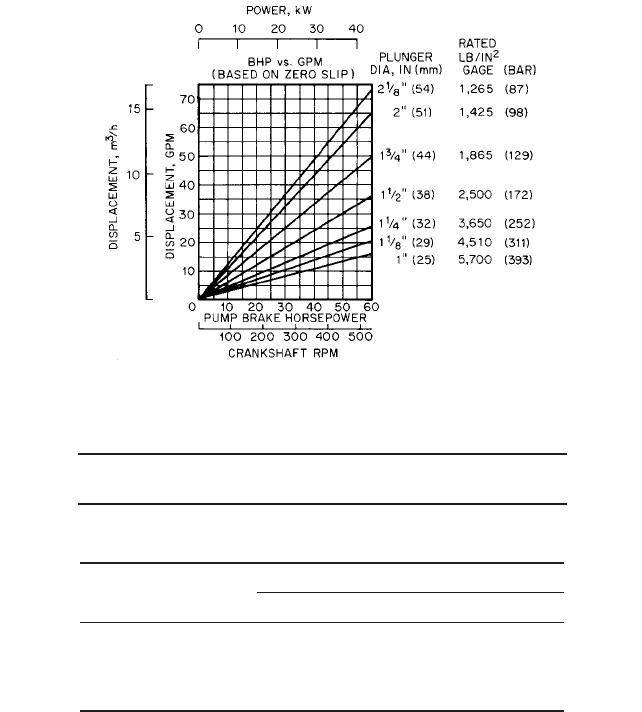
suction pressure. Figure 1 shows a typical performance curve for a power pump.
D 12A a2m n s 6 10
5
D 12A a2m n s>231
D A m n s 6 10
5
D A m n s>231
kW Q Ptd>36 ME
bhp Q Ptd>1714 ME
3.1 POWER PUMP THEORY 3.5
TABLE 1 Slip in a pump with a plate valve
Centistokes 100 1,000 2,000 6,000 10,000 12,000
Slip, % 8 8.5 9.5 20 41 61
FIGURE 1 Typical power pump performance: brake horsepower versus gallons per minute (kilowatts versus m
3
h)
based on zero slip (Flowserve Corporation)
Slip Slip (S) is the loss of capacity due to internal and external pump leakage. External
leakage occurs primarily through the stuffing box via the packing. Internal leakage is pri-
marily the backflow past the suction and discharge valves. Backflow occurs when a valve
remains open for a fraction of a second as the plunger or piston reverses direction. A small
amount of leakage may occur across the piston in a double acting pump from the high
pressure side to the low pressure side. Slip is expressed as a percentage loss of the suc-
tion capacity and is typically 1% to 4%:
where S Slip, %
B Leakage through the stuffing box
V Backflow across the valves
L Internal leakages
Fluid viscosity, pump speed, and discharge pressure can all have an effect on slip,
which is shown in Tables 1 and 2.
S B V L
TABLE 2 Slip as a function of pump speed and pressure
Slip, %
Pressure, lb/in
2
(bar) At 440 rpm At 390 rpm At 365 rpm
4000 (275) 11 22 34
3000 (207) 9 20 31
2000 (138) 7 18 30
1000 (69) 7 15 27.5

3.6 CHAPTER THREE
TABLE 3 The effect of speed on mechanical
efficiency at a constant developed pressure
% of full speed 44 50 73 100
ME,% 93.3 92.5 92.5 92.5
TABLE 4 The effect of pressure on mechanical efficiency at constant speed
% of full-load developed pressure 20 40 60 80 100
ME,% 82 88 90.5 92 92.5
Mechanical Efficiency The mechanical efficiency of a power pump is
In USCS units
In SI units
where P
in
is the input power from the driver, bhp (kW).
The mechanical efficiency of a power pump is the sum of all the frictional losses in the
fluid and power ends.These include the plungers and packing, the crossheads, the rod seals,
and the bearings.The efficiency of a single acting pump often exceeds 90%, while a double-
acting piston pump will be 88% due to the additional piston and rod seals. If the pump is
equipped with internal gearing, an additional 2% loss is common.
Most power pumps are designed to accept a range of plunger or piston sizes.When the
larger plungers are used, the increased diameter of the packing/seals and plunger/liners
will result in higher frictional losses than with smaller components.As a rule, doubling the
plunger/piston diameter will decrease the mechanical efficiency by 8%. Mechanical effi-
ciency is also affected by speed and, to a lesser extent, by developed pressure, as indicated
in Tables 3 and 4.
Speed Pump speed, or, more correctly, stroke rate, is one of the most critical selection
criteria for power pumps. The rotating and reciprocating parts of the power end, as des-
ignated, are often capable of speeds twice that of the actual pump rating. The maximum
pump speed is determined by the design of the fluid end, the hydraulic capability of the
anticipated suction system, and the required life of the plungers, packing, and valves. Most
power pump standards limit the plunger speed from 140 to 280 ft/min (0.71 to 1.42 m/s).
The plunger speed is
In USCS units
In SI units
where Sp plunger or piston speed, ft/min (m/s).
s stroke of the pump, in (mm) (half of the linear distance the plunger or
piston moves in one revolution)
n rpm of pump
All pumps have a minimum speed limit, usually determined by a decrease in the ade-
quate lubrication to the bearings in the power end.
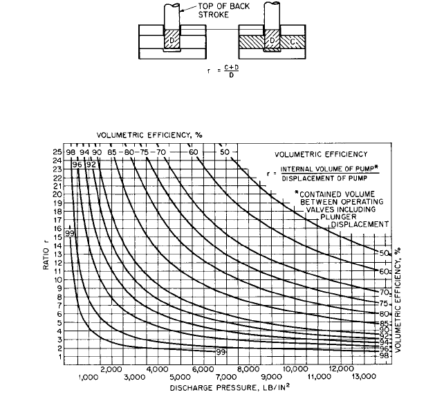
Volumetric Efficiency Volumetric efficiency (VE) is the ratio of the discharge volume
to the suction volume, expressed as a percentage, plus the slip. It is proportional to the
ratio r and the developed pressure where r is the ratio of the internal volume of fluid
between valves when the plunger or piston is at the top of the peak of its back stroke (C
D) to the plunger or piston displacement (D) (see Figure 2).
Sp s n>30,000
Sp s n>6
ME power out>power in P
out
>P
in
Q Pdt>36 P
in
ME power out>power in P
out
>P
in
Q Pdt>1714 P
in
3.1 POWER PUMP THEORY 3.7
FIGURE 2 The ratio r (Flowserve Corporation)
FIGURE 3 Volumetric efficiency (Flowserve Corporation) (lb/in
2
0.69 bar)
Since the discharge volume cannot be readily measured at discharge pressure, it is
taken at suction pressure. Taking the discharge volume at the suction pressure results in
a higher volumetric efficiency than using the calculated discharge volume at discharge
pressure because of fluid compressibility. Compressibility becomes important when pump-
ing water or other liquids over 6000 lb/in
2
(414 bar), and it should be taken into consider-
ation when determining the actual delivered capacity into the discharge system.
Figure 3 shows the approximate volumetric efficiency for water (not including slip).
Based on the expansion back to suction capacity,
Based on discharge capacity,
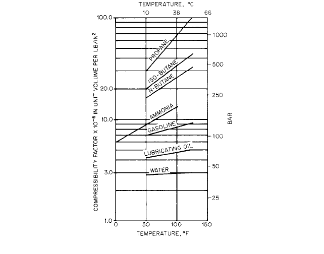
where b is the compressibility factor of the liquid being pumped. Figure 4 shows approxi-
mate values of b for various liquids.
When the compressibility factor is not known, but the suction and discharge density
can be determined in pounds per cubic foot, the following equations can be used for calcu-
lating VE:
Based on suction capacity,
VE r 1p
d
>p
s
21r 12 S
VE 11 Ptd b r2 S
VE 11 Ptd b r2> 1 1 Ptd b2 S
3.8 CHAPTER THREE
FIGURE 4 Compressibility factor (Flowserve Corporation) (bar 14.5 lb/in
2
)
Based on discharge capacity,
where p
s
suction density
p
d
discharge density
S slip
Torque The average torque required by a power pump is independent of the pump
speed, assuming the suction and discharge pressures are held constant. This means that
the pump is a “constant torque” device and, unlike a centrifugal pump, will have a flat
speed-torque curve. The torque required at the input shaft is as follows:
In USCS units
In SI units
where M pump torque, lb-ft (N m)
n speed, rpm
p power, bhp (kW)
Break-away torque, or start-up torque, is the torque required to initiate the motion of
the pump to enable it to accelerate to a constant speed. If the pump is started against an
open bypass to pump suction, the torque requirement is 25% of the running torque. If the
pump is started against full discharge pressure, the torque requirement is 125% of the
running torque. When selecting a drive system, the break-away torque of the pump must
be considered. Special “high torque” motors are often required if the pump is to be started
under the load.
M p 9.549>n
M p 5250>n
VE 1 r11 p
s
>p
d
2 S

If a variable frequency drive (VFD) is used for pump speed/capacity control, torque
fluctuations or pulsations may require the drive manufacturer to provide special elec-
tronic dampening circuits. The normal pulsating flow of the pump causes the input
power to fluctuate at approximately the same magnitude as the flow pulses. The fre-
quency of these pulses per revolution of the crankshaft is twice the number of cylinders
(see Table 5).
If the pump has internal gearing, or if the pump is being driven by an external gear
reducer, the torque pulsation values listed should be divided by the gear ratio.
Derating Power pumps can be derated in order to achieve acceptable performance or
part life in a variety of special applications. The most common derating is pump speed.
Experience has shown that the life of fluid-end expendable parts, such as plungers, pack-
ing, and valves, can be extended if the pump speed/plunger velocity is reduced when
pumping certain fluids. Some guidelines for acceptable plunger speeds are shown in
Table 6.
Pumping high-viscosity fluids may also require the speed of a power pump to be der-
ated. Some attempts have been made to establish standards for speed derating as a func-
tion of the fluid viscosity. Unfortunately, these methods have been based on power pump
designs that were established for water or similar low-viscosity services. If a pump has
been designed specifically for a high-viscosity service, only moderate speed derating may
be required. Generally, pumps designed with large internal fluid passages, low-valve veloc-
ities, and larger plungers or pistons will need less derating.
Power pumps should be derated for a rod load if system or process “upsets” cannot be
avoided. These are usually applications where the gas content of the pumped fluid can
lead to abnormal pressure pulsations or cavitations in the fluid cylinder.
3.1 POWER PUMP THEORY 3.9
TABLE 6 Guidelines for acceptable plunger speeds
Fluid Plunger Speed, ft/min (m/s)
Cold water 315
—
354 (1.6
—
1.8)
Hot water 140
—
194 °F (60
—
90 °C) 217
—
256 (1.1
—
1.3)
Hot water over 194 °F (90 °C) 157
—
217 (0.8
—
1.1)
Salt water 236
—
276 (1.2
—
1.4)
Cold oil 315
—
354 (1.6
—
1.8)
Hot oil 256
—
295 (1.3
—
1.5)
Crude oil 217
—
276 (1.3
—
1.5)
Liquid ammonia 197
—
236 (1.0
—
1.2)
Carbamate 138
—
158 (0.7
—
0.8)
Slurry 158
—
197 (0.8
—
1.0)
Fatty acid 236
—
295 (1.2
—
1.5)
Light hydrocarbons 177
—
236 (0.9
—
1.2)
Glycol 256
—
295 (1.3
—
1.5)
High viscosity liquids 138
—
197 (0.7
—
1.0)
TABLE 5 The pulses per revolution and pulse amplitude for various pump types
Pump Type No. of Cylinders Pulses per Rev. Pulse Amplitude
Duplex, double-acting 4 8 24% 22%
Triplex, single-acting 3 6 6% 17%
Quintuplex, single-acting 5 10 2% 5%
Septuplex, single-acting 7 14 1.2% 2.6%
Nonoplex, single-acting 9 18 0.6% 1.5%
3.10 CHAPTER THREE
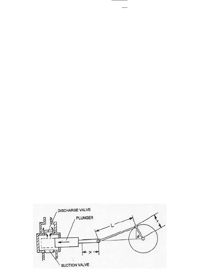
FIGURE 5 Slider-crank mechanism
FLUID END THEORY __________________________________________________
Pumping Cycle
Unlike the relatively smooth, continuous flow of fluid through a cen-
trifugal pump, the flow of fluid through a power pump occurs in a transitory dynamic con-
dition called a pumping cycle. The event that initiates this cycle is the linear movement
of the plunger or piston. In Figure 5, r is the radius of the crank in feet (meters), L is the
length of the connecting rod in feet (meters), C equals L / r, and v equals (2p / 60) rpm.
Thus, X , the linear movement of the piston or plunger is
As the plunger (or piston) withdraws from the fluid cylinder or pumping chamber, the
volume of the cylinder increases.The pressure in the cylinder decreases in response to the
increased volume. Since most of the fluids handled by power pumps are relatively incom-
pressible, very little plunger movement is required to cause a pressure drop. When the
cylinder pressure drops sufficiently below suction pressure, the differential pressure
begins to open the suction valve. The valve opens gradually and smoothly at the start of
the suction stroke because the velocity and acceleration of the plunger are small.
Fluid flows through the suction valve assembly, following the plunger and filling the
cylinder. As the plunger decelerates at the end of the suction stroke, the suction valve
gradually returns to its seat. Ideally, the suction valve is completely closed as the plunger
comes to a stop.
The motion of the slider-crank mechanism causes the plunger to reverse direction and
start its discharge stroke. The fluid trapped in the fluid cylinder is compressed until the
cylinder pressure exceeds the discharge pressure by an amount sufficient to begin to open
the discharge valve.As with the suction valve, the discharge valve continues to open until
it reaches its travel limit or until the velocity of fluid through the valve becomes constant.
As the plunger decelerates, the valve moves back toward its seat. Again, ideally, the dis-
charge valve closes when the motion of the plunger stops.
The number of pumping cycles in a single revolution of the crankshaft is the same as
the number of cylinders in the pump. Every cylinder will “pump” in a sequence determined
by the “firing order” of the crankshaft. The cylinders are arranged in parallel, with each
one discharging into a common discharge manifold. In industry terms, the pump is usually
identified by the number of plungers or pistons on the crankshaft. They are the same for
single- or double-acting pumps (see Table 7).
Pulsations The pulsating characteristics of the fluid flowing into and out of power
pumps are significantly influenced by the number of plungers or pistons. Discharge flow
pulsations are the most critical because of the high energy potential generated when the
system resistance reacts with the flow to create pressure. Since the magnitude of the dis-
charge pulsation is mostly affected by the number of cylinders, increasing the number of
cylinders will reduce the flow pulsations.
X r c1 cos u L a1
B
1
r
2
L
2
1sin u2
2
bd