Pump Handbook by Igor J. Karassik, Joseph P. Messina, Paul Cooper, Charles C. Heald - 3rd edition
Подождите немного. Документ загружается.

2.436 CHAPTER TWO
12. American National Standard. Procedures for Balancing Flexible Rotors, ANSI S2.42,
New York, 1982.
13. American National Standard. Balance Quality of Rotating Rigid Bodies, ANSI S2.19,
New York, 1975.
FURTHER READING __________________________________________________
Bloch, H. P. “Improve Safety and Reliability of Pumps and Drivers.” Hydrocarbon Process-
ing, May 1977, p. 213.
Bussemaker, E. J. “Design Aspects of Baseplates for Oil and Petrochemical Industry
Pumps.” IMechE Paper C45/81, Netherlands, 1981, p. 135 (English ed.).
Jackson, C. “Alignment of Pumps.” Centrifugal Pump Engineering Seminar, ASME South
Texas Section Professional Development, Sec. 9, Houston, 1979.
Jackson, C. “Alignment of Rotating Equipment.” NPRA, MC-74-7, Houston, 1974.
Sprinker, E. K., and F. M. Patterson. “Experimental Investigation of Critical Submergence
for Vortexing in a Vertical Cylindrical Tank.” ASME Paper 69-FE-49, June 1969.
Von Nimitz, W. W. “Dynamic Design Criteria for Reciprocating Compressor and Pump
Installations.” Presented at the 27th Annual Petroleum Mechanical Engineering Confer-
ence, New Orleans, September 19, 1972.
Wachel, J. C., and C. L. Bates. “Escape Piping Vibrations While Designing.” Hydrocarbon
Processing, October 1976, p. 152.
2.3.4
CENTRIFUGAL PUMP MINIMUM
FLOW CONTROL SYSTEMS
HORACE J. MAXWELL
DAVID A. KALIX
2.437
In designing centrifugal pumps, engineers strive to develop specific internal geometry
that will produce head and flow with low energy loss. Each pump is designed for a specific
head versus flowrate for the given impeller speed. The head and flowrate on this family
of “characteristic” curves where the energy loss is minimum is known as the Best Effi-
ciency Point (BEP).
In application, pumps spend a significant portion, if not all of their life, operating at
conditions other than BEP. This is normal and is due to a combination of system design
conditions (for example, static head, piping and valve impedances, and so on), available
pump designs (that is, capacities and heads) and actual plant operating requirements.
Low flow related problems occur when pumps continuously operate in or repetitively cycle
into flow regions that are significantly below the BEP (for example, 50% of BEP). In these
low-flow regions, pump and system component performance and longevity can be
adversely affected.
Low flow problems are known to be worst for large high-energy pumps (for example,
boiler feedwater), for pumps handling hot liquids, for pumps that handle liquids that have
solid particles, and for pumps for low net positive suction head (NPSH) service. A well-
designed minimum flow control system can establish an environment that will substan-
tially improve pump and system performance. The following chapter will briefly review
the topics that should be considered when designing a minimum flow system for a cen-
trifugal pump.
FACTORS AFFECTING LOW FLOW RATE PUMP OPERATION________________
Collectively, the following broadly classed factors have been recognized as the major con-
tributors to low flow pump problems.
2.438 CHAPTER 2
Thermal Factors The increase in temperature of the liquid within the pump is directly
related to the pump’s efficiency. The energy that is available to heat the flowing liquid and
the pump casing is basically the difference between the power input to the pump (brake
horsepower) and the useful work done by the pump (liquid horsepower). At low flow con-
ditions, centrifugal pumps are very inefficient and a significant amount of input energy
is lost and heats the liquid and the pump assembly. Refer to Subsection 2.3.1 and Chap-
ter 12 for more discussion on thermal effects.
Hydraulic Instabilities When the pump is operating significantly below the BEP, flow
streamlines (that is, patterns) within the pump change considerably from the rated design
streamlines. Fluid eddies are most likely to develop at the inlet and discharge of the
impeller resulting in flashing, cavitation, and shock waves that often produce vibration
and serious component erosion. This phenomenon is classically known as internal recir-
culation. It can occur at the pump inlet (suction) and discharge. Refer to Subsection 2.3.1
and 2.3.2 for a more in-depth discussion on this topic.
Mechanical Loads As the flowrate through the pump decreases, steady state loads
increase and superimposed dynamic cyclic loads appear radially and axially on the
impeller and shaft. The dynamic cyclic component increases significantly when recircu-
lation within the pump occurs. Bearing damage, shaft and impeller breakage, and rub-
bing wear on casing, impeller and wear rings can occur. See Subsections 2.3.2 and 2.3.3
for discussion of this subject.
Axial-flow and mixed-flow pumps with high specific speed produce comparatively
higher head and take comparatively more power at low flow. A bypass system may be nec-
essary not only to reduce component loading and stress but also to prevent motor overload.
See Subsection 2.3.1 and Section 8.1 for discussion.
Abrasive Fluids Liquids containing a large amount of abrasive particles, such as sand
or ash, must flow continuously through the pump. If flow decreases, the particles can
circulate inside the pump passages and quickly erode the impeller casing, wear rings,
and shaft.
ESTABLISHING MINIMUM PUMP FLOW REQUIREMENTS ___________________
The bypass system designer must know the minimum pump flow specified by the pump
manufacturer in order to properly design a bypass system. The four previously discussed
topics should be evaluated in detail by the pump manufacturer to establish the minimum
flowrate specification. Minimum flowrate specifications are generally established
through a combination of analytical and experimental techniques coupled with field per-
formance data.
Thermal Considerations The maximum allowable temperature rise of the pump is pri-
marily based on two points: the permissible pump casing and shaft thermal growth and
the flash point temperature of the pumpage. Pump manufacturers use analytical, labo-
ratory and field data to validate their thermal analysis to ensure that pumps do not seize
within the allowable temperature operating ranges. Refer to Subsection 2.3.1 for tem-
perature rise calculations.
Applications involving extremely high or low temperature fluids may require more in-
depth analysis to determine if individual component thermal growth is the limiting factor
in determining minimum flowrate. Additionally, certain chemicals, which polymerize or
solidify at particular temperatures, may establish the minimum flowrate specification.
Chapter 12 and Subsection 2.3.1 provide more detail on this subject.
Hydraulic Considerations The minimum bypass flow requirement for most pumps is
based on minimum continuous stable flowrate, a hydraulic criterion, rather than a tem-
perature rise. Pump internal recirculation will occur at both the impeller inlet and
2.3.4 CENTRIFUGAL PUMP MINIMUM FLOW CONTROL SYSTEMS 2.439
impeller outlet as flowrates are reduced. Internal recirculation will occur at flowrates well
above those that cause temperature concerns. Refer to Subsection 2.3.1 for a detailed eval-
uation of this topic.
Mechanical Considerations It is necessary to know how head, radial thrust, axial
thrust and power vary with capacity before deciding on minimum allowable flow. Bear-
ing capacity, motor rating, and stresses in drive and driven components are important
influences.
Abrasive Wear Considerations Relatively high bypass flowrates may be required to
protect the pump against abrasives in the liquid. Heavy wear can occur at flows below
85% of the best efficiency point. The designer must establish the minimum pump flow
specification using the pump manufacturer’s recommendation and his experience with
comparable pumps and liquid/solid mixtures.
MINIMUM FLOW CONTROL SYSTEM DESIGN FACTORS ____________________
Pump Size
Capacity, power, specific speed, and suction specific speed are all factors that
must be examined when designing a bypass system. These factors have a direct impact
on the cost of building and operating the bypass system. Use of a continuous bypass sys-
tem will require an even larger pump and driver to supply both the process and bypass
flow requirements simultaneously.
Discharge Pressure High discharge pressures result in high head loss in bypass
valves, components, and lines. Liquids that can flash and cavitate demand special pre-
cautions to minimize damage in valving, orifices, and piping.
Available Heat Sink Bypass flow must be reintroduced into the system far enough
upstream to prevent progressive temperature buildup or flow disturbance in the pump
suction. This may mean a simple discharge back to an uninsulated inlet line or discharge
to a receiving tank or cooler with enough area and enough inflow of cool liquid to handle
the thermal load. Bypass flow can discharge into a deaerator storage tank, a condenser,
a flash tank, or a cooling pond. Elevation, distance, and pressure inside the receiving tank
are also factors, as is the fact that the interior must be available for inspection and for
repair of spargers, spray or distribution pipes, orifices, and backpressure regulators.
Pump Design A pump’s design and materials of construction often affect the minimum
allowable percentage of flow. With thermal effects, pumps vary in the length of time that
they will tolerate shut off or low flow. This is important in designing the bypass system
valves, instrumentation, and controls.
Hydraulic effects at low flow are most apparent in high-energy pumps.The pump man-
ufacturer should state the continuous minimum hydraulically acceptable flow for a given
pump
—
and how it was determined. With axial-flow pumps, the shape of the pump head
curve may be a factor in selecting the required bypass flow percentage. If feasible, a wit-
ness shop test of the pump should be specified to demonstrate and verify minimum flow
recommendations.
Liquid Pumped Liquids that flash and cavitate generally required a high bypass flow
percentage. Examples are liquids near the boiling point or at high pressure. Abrasives in
the liquid may require more bypass than would be needed for thermal reasons alone.
Energy Costs A high energy cost to operate the pump requires careful consideration
of bypass system design. The evaluation should compare equipment installation costs,
maintenance, and energy costs for various bypass configurations. Figure 1 shows the
annual pumping costs for a continuous bypass type system based on bypass flow, pres-
sure and energy rates. The example shows a pump with a discharge head of 500 ft (152
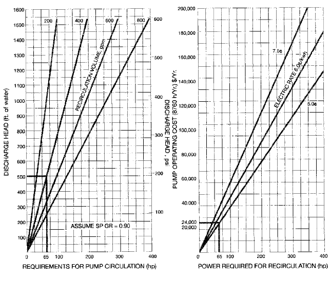
2.440 CHAPTER 2
FIGURE 1 Annual pumping cost estimate for continuous bypass systems (metric conversions: ft 0.3048 = m,
gpm 0.277 = m
3
/h, hp 0.746 = W)
m) and a bypass flow requirement of 400 gpm (91 m
3
/h). Based on an energy cost of 5.0
cents/KWH, the annual cost for continuous bypass is $24,000. An automatic bypass sys-
tem will only open the bypass when process flow demand is low. The total design life
energy costs of a continuous bypass system can easily exceed the hardware costs of an
automatic bypass system.
Noise Considerations Bypass systems can easily exceed OSHA requirements for occu-
pied spaces if not designed properly. High pressure drops and high fluid velocity increase
noise. Multi-stage pressure reduction, heavy wall pipe, insulation, and silencers will all
combine to reduce noise to acceptable levels. See Section 8.4 for a further discussion of
this topic.
Process System Design and Operational Expectations Bypass system design will
depend on the plant design life and the expected process operational requirements. For
example, a swing-loaded electric power plant will have far different pump operating
requirements than a low-pressure emergency fire water system. The bypass system
designer must evaluate installation, maintenance, and operating costs for the life of the
process system with the expected utilization. If the actual operating conditions differ sig-
nificantly from the design, the configuration of the bypass system should be reevaluated.
For example, a process designed for normal operation with one pump at 75% of maximum
capacity may put severe demands on the bypass system if the pump is operated continu-
ously at 20% of maximum capacity.
2.3.4 CENTRIFUGAL PUMP MINIMUM FLOW CONTROL SYSTEMS 2.441
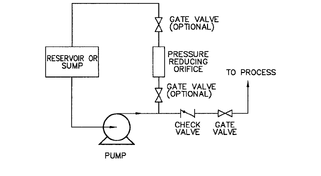
FIGURE 2 Typical continuous bypass system
LOW FLOW PROTECTION SYSTEMS ____________________________________
Bypass Systems
—
Types/Design Considerations
CONTINUOUS BYPASS SYSTEMS As the title implies, continuous bypass systems provide con-
tinuous flow whenever the pump is running, regardless of the process demand. Figure 2
illustrates a simple system, with a bypass line branching off the pump discharge upstream
of the main line check valve and containing a fixed orifice dimensioned by analysis to pro-
vide minimum required pump flow. The bypass line discharges into a reservoir that is at
a lower pressure than the pump discharge. The bypass line can also discharge directly
into the pump supply line. However, the piping system design must ensure that the bypass
liquid temperature does not increase to an unacceptable level. Additionally, vapor bubbles
formed in the bypass by the pressure reduction process may be introduced into the pump.
This will affect pump performance and longevity. Locating the bypass branch-off before
the discharge check valve as shown keeps backflow from the process or from a parallel
operating pump from going back to the receiving tank or back through the pump during
a pump shutdown. Consideration should also be given to installing a check valve in the
bypass line.
The size of the bypass pipe depends on flow and piping configuration. If the pressure
drop through the orifice results in flashing flow, the orifice should be located at the end of
the bypass piping and should discharge directly into the larger receiving tank or larger
downstream piping. The discharge flow should be directed so it does not impinge on the
walls of the receiving tank but rather into the liquid to absorb the force of cavitation implo-
sion. Valves and fittings located immediately downstream of the orifice may be damaged
by cavitation. Full ported gate or ball valves are less susceptible to damage.Waterhammer
and erosion are not problems in well-designed continuous bypass systems.
The pump and prime mover must be sized to simultaneously supply both the bypass
flow and the maximum process flow at the required pump discharge pressure.
AUTOMATIC BYPASS SYSTEMS
Automatic recirculation systems control the bypass flow in
relation to the process flow. The sum of the process and bypass flowrates will always
exceed the minimum flowrate specified to protect the pump. Two essential elements of
these systems are a device to measure the process flow and a device to control the bypass
flow. Compared with continuous bypass, these systems reduce energy consumption and
pump horsepower requirements.
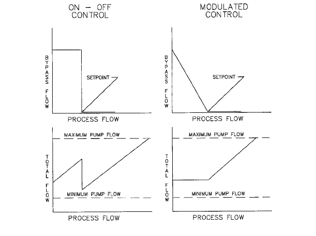
The bypass flow can be regulated by either “Modulated” or “On-Off” control. When
bypass flow is “Modulated,” the bypass flow is inversely proportional to the process flow.
2.442 CHAPTER 2
FIGURE 3 Comparison of On-Off versus Modulated automatic bypass flow control.
The bypass is shut when process flow is greater than the control setpoint (that is, mini-
mum flowrate required), opens more as the process flow is reduced, and is full open when
the process flow is zero. With “On-Off” bypass control, the bypass is open fully when
process flow is below the setpoint and is shut when the process flow is above the setpoint.
Figure 3 illustrates these control methods and the effect on total pump flow. The total
pump flow is the sum of the process and bypass flows; it is the flow that enters the pump
suction. The “On-Off” control graph shows that there is a step change in the total flow
when the bypass opens or closes. The “Modulated” control regulates the total flow
smoothly when the process flow is below the setpoint. Either method will protect the pump
from damage due to low flow. However, “On-Off” control may produce large pump dis-
charge pressure variations depending on the shape of pump head curve. Rapid pump flow
changes may produce damaging hydraulic or mechanical shocks. This will reduce pump
life and increase maintenance. Modulated bypass control is required when the minimum
flowrate specification exceeds approximately forty percent of the rated pump capacity. If
“On-Off” bypass control is used above this point, the pump may exceed its capacity rating
with resultant pressure pulsation and unsteady flow.
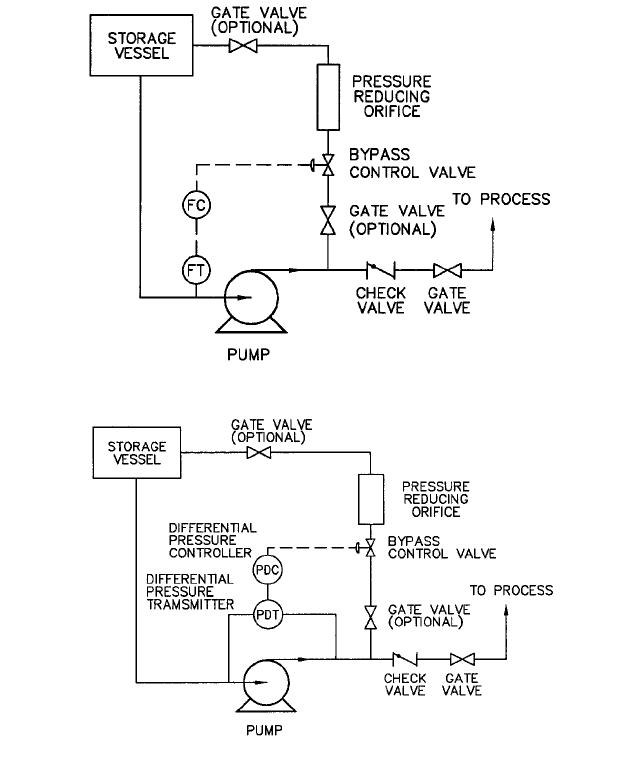
CONTROL LOOP SYSTEMS A typical automatic bypass system, based on an instrumented flow
control loop, is shown in Figure 4. This system requires a flow meter, a check valve, a
bypass control valve, a valve controller and a pressure-reducing orifice.
The flow meter can be placed at the pump inlet or discharge before the bypass tee (as
opposed to it having to be placed after the bypass tee in an “On-Off” system). The con-
troller compares the flow meter signal with the setpoint (minimum pump flow required)
and operates the bypass control valve.
Single stage control valves are commonly used in low pressure systems with an orifice
for pressure reduction located downstream. However, these are not suitable for high pres-
sure differentials or for the controlling of cavitation or flashing. Pressure reducing valves
with multi-stage trim, good seat tightness, and low pressure recovery characteristics are
widely used in this service. Refer to Chapter 7 for a detailed discussion of control valve
characteristics and selection.
2.3.4 CENTRIFUGAL PUMP MINIMUM FLOW CONTROL SYSTEMS 2.443
FIGURE 4 Typical automatic bypass system based on flow control
FIGURE 5 Typical automatic bypass system based on pump differential head
The bypass pressure reducing orifice handles the high velocity and erosive forces of the
bypass flow. However, the handling of cavitation and flashing by this fixed restriction is
limited. The orifice is sized to operate properly at one bypass flow condition. At low flows,
the orifice does not provide the correct pressure reduction as designed.
The check valve is placed in the main line, as shown in Figure 4, to prevent reverse flow
through the pump. The pump and motor bearings can be damaged if rotated in reverse.
Pressure drop through the check valve must be considered in pump sizing in addition to
other piping and valve pressure losses.
A typical automatic bypass system based on pump differential head is shown in Figure
5. This system is identical to the flow controlled bypass system except that pump differ-
ential head is measured instead of flow. This system can only be used with continuously
rising pump head characteristic curves. The system will have to be adjusted for each indi-
vidual pump characteristic and later adjusted if this characteristic changes over the life of
the pump.
2.444 CHAPTER 2
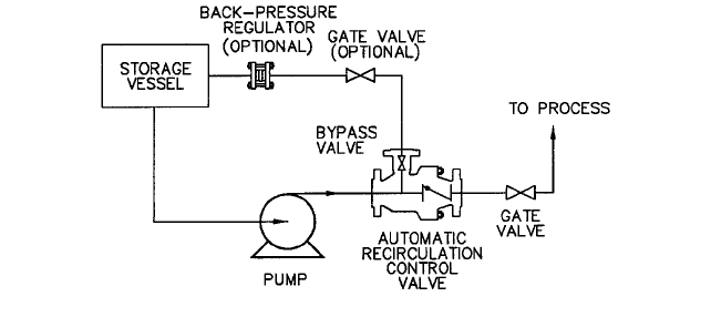
FIGURE 6 Typical ARC valve bypass system
Depending on the bypass valve and control instrumentation selected, these systems
can provide either “Modulating” or “On-Off” bypass control. Valves, instrumentation, and
controls must be individually sized for the service conditions.All components must be inte-
grated together to provide bypass flow control that meets the pump and process opera-
tional design criteria.
The Automatic Recirculation Control (ARC
®
) Valve This valve provides bypass flow
control, pressure reduction, and reverse flow pump protection all within a single unit.This
single valve combines the functions of the check valve, pressure reducing orifice, pipe tee,
control instrumentation flow meter, and bypass control valve that are all required in the
instrumented control loop bypass system. Valves can be designed to provide either “Mod-
ulated” or “On-Off” bypass control. The operation of all ARC valves is fundamentally the
same. The flow sensing element (check valve disc) responds to the process flow demand
and opens or closes the self-contained bypass control valve. Differences in ARC valve
design center around bypass valve actuation method, repairability, serviceability, and
adjustability. Figure 6 illustrates a typical ARC valve bypass system.
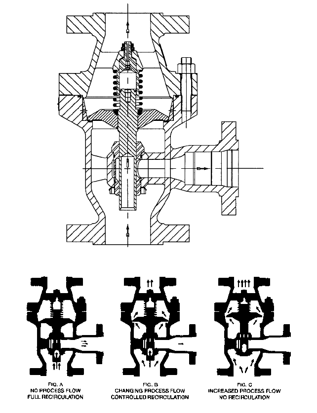
Pilotless Trim Design The simplest of ARC valve designs operate the bypass flow con-
trol valve directly by the flow sensing element. The construction of a typical ARC for low
pressure service is shown in Figure 7. The basic operation of this valve is shown in Fig-
ure 8. At zero main flow (“A”), the bypass provides full recirculation flow. As main flow
increases (“B”), the bypass modulates proportionally closed. At full main flow (“C”), the
bypass is shut. The pressure reduction from the pump discharge to the bypass is accom-
plished by the characterized orifices in the bypass element that is attached to the disc.
However, the differential pressure from inlet to bypass imposes static and dynamic forces
on the disc assembly. These unbalanced forces interfere with the normal disc motion and
limit the maximum differential pressure for pilotless trim. There is an upper differential
pressure limit at which this design will not operate satisfactorily and pilot operated
bypass control must be used.
Pilot Operated Trim Pilot operated bypass control valves utilize a combined hydraulic-
mechanical force to control the bypass flow. Only a relatively small mechanical force is
necessary to hydraulically generate the large forces required to operate a bypass flow con-
trol valve in a high-pressure system. Figure 9 illustrates a pilot-operated bypass that uti-
lizes a lever connected to the check valve disc to actuate the pilot. Figure 10 illustrates a
pilot operated multistage bypass operated by an in-line pilot valve. Pilot-operated valves
require more components and seals than unbalanced valves and are therefore more costly.
2.3.4 CENTRIFUGAL PUMP MINIMUM FLOW CONTROL SYSTEMS 2.445
FIGURE 7 Construction of a typical ARC valve for low-pressure service
FIGURE 8A through C Basic ARC valve operation at three process flow conditions
Serviceability ARC valves can be designed for in-line serviceability. Access is provided
to the valves internal components for inspection or repair without disturbing the process
or bypass piping. Figure 11 illustrates a valve designed to be serviced in-line.
SAFETY SHUTDOWN SYSTEMS ________________________________________
These controls are normally provided as backup pump protection for the continuous bypass
and automatic bypass control systems.They should only operate if the normal system fails
due to mechanical or operator causes. In each case, the protection system trips the pump off.