Pump Handbook by Igor J. Karassik, Joseph P. Messina, Paul Cooper, Charles C. Heald - 3rd edition
Подождите немного. Документ загружается.

2.4 CENTRIFUGAL PUMP PRIMING 2.457
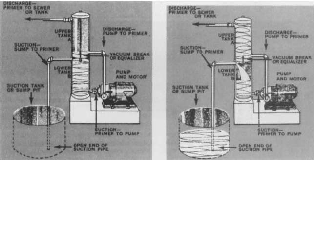
Phantom View of Primer in Use with Pump Stopped (left)
When the pump stops, the liquid in the upper chamber runs back into the pump and lower chamber of primer by
gravity, thus refilling them with liquid and keeping the pump always ready for starting.
Phantom View of Primer in Use with Pump Running (right)
When the pump starts, it draws liquid from the lower chamber and discharges it through the upper chamber.
Withdrawal of liquid from the lower chamber creates a partial vacuum in this chamber, which causes the liquid in
the sump or well to rise in the suction pipe and flow through the primer to the pump.
FIGURE 2 Two-chamber priming tank (Apco/Valve and Primer)
Each time the pump is stopped and restarted, a quantity of liquid in the priming tank
must be removed to create the required vacuum. Because of possible back siphoning, the
liquid volume in the tank is reduced. Unless the priming tank is refilled, it has limited
use. Automatic refilling of the priming tank cannot occur if the pump has a discharge
check valve unless there is sufficient backflow from the discharge system before the check
valve seats.
Because of their size, the use of single-chamber priming tanks is restricted to installa-
tions of relatively small pumps, usually to a 12-in (305-mm) suction line (approximately
2000 gpm [450 m
3
/h]).
The Two-Chamber Tank This type of priming tank is an improvement over the single-
chamber design. It consists of integral suction and discharge chambers connected by a vac-
uum breaker or equalizing line. The operation and automatic refilling feature of this
device are shown in Figure 2. Commercial priming chambers are readily available with
proper automatic vents and other features.
PRIMING INDUCTORS_________________________________________________
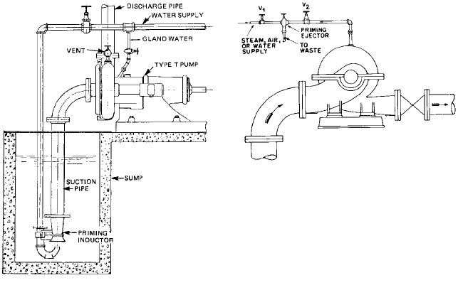
If a separate source of liquid of sufficient capacity and pressure is available, it can be used
to fill the suction line of the pump to be primed through the use of an inductor, as shown
in Figure 3. For water, the pressure must be equal to about 4 lb/in
2
for each foot (90 kPa
for each meter) of head necessary to prime the pump, measured from the lowest liquid
level in the sump from which priming must be accomplished to the top of the pump. The
amount of liquid necessary depends on the pressure.
Because the inductor is a positive-pressure device, leaks in the suction line or at the
pump seal or stuffing box are not critical. The service liquid can be left on or turned off
2.458 CHAPTER TWO
FIGURE 3 Priming inductor (Nagle Pumps)
FIGURE 4 Arrangement of priming with an ejector
after pumping is initiated. If left on, the head developed by the pump (therefore the flow
also) will be increased.
An additional feature of the priming inductor is that operation is possible even when
the suction line is covered with sediment. When the pump and suction line are filled, back-
flow results, mixing the solids and the liquid.
TYPES OF VACUUM DEVICES __________________________________________
Almost every commercially made vacuum-producing device can be used with systems in
which pumps are primed by evacuation of air. Formerly water-jet, steam-jet, or air-jet
primers had wide application, but with the increase in the use of electricity as a power
source, motor-driven vacuum pumps have become more popular.
Ejectors Priming ejectors work on the jet principle, typically using steam, compressed
air, or water as the operating medium. A typical installation for priming with an ejector
is shown in Figure 4. Valve V
1
is opened to start the ejector, and then valve V
2
is opened.
When all the air has been exhausted from the pump, liquid will be drawn into and dis-
charged from the ejector. When this occurs, the pump is primed and valves V
2
, and V
1
are
closed, in that order.
An ejector can be used to prime a number of pumps if it is connected to a header
through which the individual pumps are vented through isolating valves.
Dry Vacuum Pumps Dry vacuum pumps, which may be of either the reciprocating or
the rotary oil-seal type, cannot accommodate mixtures of air and liquid. When they are
used in priming systems, some protective device must be interposed between the cen-
trifugal pump and the dry vacuum pump to prevent liquid from entering the vacuum
pump. The dry vacuum pump is used extensively for central priming systems.
Wet Vacuum Pumps Any rotary, rotative, or reciprocating pump that can handle air or
a mixture of air and liquid is classified as a wet vacuum pump. The most common type
2.4 CENTRIFUGAL PUMP PRIMING 2.459
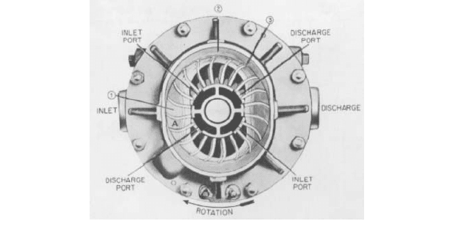
FIGURE 5 Operating principle of the Nash Hytor pump (Nash Engineering)
used in priming systems is shown in Figure 5. This is a centrifugal displacement type of
pump consisting of a round, multiblade rotor revolving freely in an elliptical casing par-
tially filled with liquid. The curved rotor blades project radially from the hub and, with
the side shrouds, form a series of pockets and buckets around the periphery.
The rotor revolves at a speed high enough to throw the liquid out from the center by cen-
trifugal force. This forms a solid ring of liquid revolving in the casing at the same speed as
the rotor, but following the elliptical shape of the casing. It will be readily seen that this forces
the liquid to alternately enter and recede from the buckets as the rotor at high velocity.
Referring to Figure 5 and following through a complete cycle of operation in a given
chamber, we start at point A with the chamber (1) full of liquid. Because of the effect of the
centrifugal force, the liquid follows the casing, withdraws from the rotor, and pulls air
through the inlet port, which is connected to the pump inlet. At (2) the liquid has been
thrown outwardly from the chamber in the rotor and has been replaced with air. As rota-
tion continues, the converging wall of the casing at (3) forces the liquid back into the rotor
chamber, compressing the air trapped in the chamber and forcing it out through the dis-
charge port, which is connected with the pump discharge. The rotor chamber is now full of
liquid and ready to repeat the cycle. This cycle takes place twice in each revolution.
If a solid stream of liquid circulates in this pump in place of air or of an air and liquid
mixture, the pump will not be damaged but it will require more power. For this reason, in
automatic priming systems using this type of vacuum pump, a separating chamber or trap
is provided so liquid will not reach the pump. Liquid needed for sealing a wet vacuum
pump can be supplied from a source under pressure, with the shutoff valve operated man-
ually or through a solenoid connected with the motor control. It is, however, preferable to
provide an independent sealing liquid supply by mounting the vacuum pump on a base
containing a reservoir. This is particularly desirable in locations where freezing may occur,
as a solution of antifreeze can be used in the reservoir.
CENTRAL PRIMING SYSTEMS _________________________________________
If there is more than one centrifugal pump to be primed in an installation, one priming
device can be made to serve all the pumps. Such an arrangement is called a central prim-
ing system (Figure 6). If the priming device and the venting of the pumps are automati-
cally controlled, the system is called a central automatic priming system.
Vacuum-Controlled Automatic Priming System A vacuum-controlled automatic
priming system consists of a vacuum pump exhausting a tank. The pump is controlled by

2.460 CHAPTER TWO
FIGURE 6 Connections for a central priming system
FIGURE 7 Vacuum-controlled central automatic priming
a vacuum switch and maintains a vacuum in the tank of 2 to 6 in Hg (50 to 150 mm Hg)
above the amount needed to prime the pumps with the greatest suction lift. The priming
connections on each pump served by the system are connected to the vacuum tank by
automatic vent valves and piping (Figure 7). The vacuum tank is provided with a gage
glass and a drain. If liquid is detected in the vacuum tank as the result of leakage in a
vent valve, the tank can be drained. Automatic vent valves consist of a body containing a
float that actuates a valve located in the upper part. The bottom of the body is connected
to the space being vented. As air is vented out of the valve, water rises in the body until
the float is lifted, and the valve is closed.
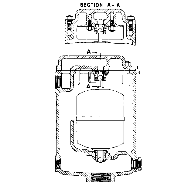
A typical vent valve designed basically for vacuum priming systems is illustrated in
Figure 8. The valve is provided with auxiliary tapped openings on the lower part of the
body for connection to any auxiliary vent points on the system
—
for instance, when air is
to be exhausted simultaneously from the high point of the discharge volute and the high
point of the suction passageways. When one or more of these vent points are points of
higher pressure, such as the top of the volute of the pump, an orifice is used in the vent line
to limit the flow of liquid. Otherwise, a relatively high constant flow of liquid from the dis-
charge back to the suction would take place, causing a constant loss. Where a unit is used
more or less constantly, a separate valve should be used for each venting point.
The system shown in Figure 7 is the most commonly used of central automatic prim-
ing systems. It can use either wet or dry motor-driven vacuum pumps. Most central prim-
ing systems are provided with two vacuum pumps. The usual practice is to have the
control of one vacuum pump switched on at some predetermined vacuum and the control
of the second switched on at a slightly lower vacuum.
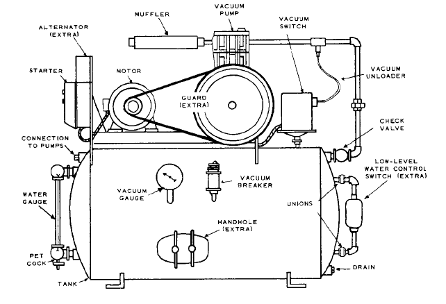
Combination dry reciprocating-type vacuum pump and vacuum tank units are com-
mercially available in various sizes. The operation of a typical unit can be explained as fol-
lows, referring to Figure 9.
The primer automatically stops and start itself to maintain a minimum vacuum in
its tank at all times, regardless of whether the centrifugal pumps it serves are operat-
ing or not.
A vacuum header is run from the primer to the centrifugal pumps, and connection is
made to the priming valve mounted on each pump. The vacuum in the primer tank
2.4 CENTRIFUGAL PUMP PRIMING 2.461
FIGURE 8 Automatic vent valve (Nash Engineering)
removes the air from the pump and suction line via the vacuum header and priming
valve. Liquid rises up the suction line and fills the pump. The liquid cannot enter the vac-
uum header because the float mechanism in the priming valve closes when the liquid
reaches it.
If, for any reason, the liquid level in the pump drops, the priming valve immediately
opens and the vacuum restores the liquid level.
The pumps are thus kept permanently primed.
Automatic priming systems using ejectors are also feasible, and several such systems
are commercially available.
SELF-CONTAINED UNITS ______________________________________________
Centrifugal pumps are available with various designs of priming equipment that makes
them self-contained units. Some have automatic priming devices, which are basically
attachments to the pump and become inactive after the priming is accomplished. Other
units, which are self-priming pumps, incorporate a hydraulic device that can function as
a wet vacuum pump during the priming period (see below). For stationary use, the auto-
matically primed type is more efficient. The self-priming designs are generally more com-
pact and are preferred for portable or semiportable use.
2.462 CHAPTER TWO
FIGURE 9 Combination dry reciprocating-type vacuum pump and vacuum tank (Apco/Valve and Primer)
An automatically primed motor-driven pump uses a wet vacuum pump either directly
connected to the pump or driven by a separate motor. In a directly connected unit, as soon
as the centrifugal pump is primed, a pressure-operated control opens the vacuum pump
suction to atmosphere so it operates unloaded. With a separately driven vacuum pump,
the controls stop the vacuum pump when the centrifugal pump is primed.
SELF-PRIMING PUMPS________________________________________________
The basic requirement for a self-priming centrifugal pump is that the pumped liquid must
be able to entrain air in the form of bubbles so the air will be removed from the suction
side of the pump.This air must be allowed to separate from the liquid after the mixture of
the two has been discharged by the impeller, and the separated air must be allowed to
escape or to be swept out through the pump discharge. Such a self-priming pump there-
fore requires, on its discharge side, an air-separator, which is a relatively large stilling
chamber, or reservoir, either attached to or built into the pump casing. Alternatively, a
small air bleed line can be installed from the discharge pipe between the pump and the
discharge check valve back to the suction source.
There are two basic variations of the manner in which the liquid from the discharge
reservoir makes the pump self-priming: (1) recirculation from the reservoir back to the
suction and (2) recirculation within the discharge and the impeller itself.
Recirculation to Suction In such a pump, a recirculating port is provided in the dis-
charge reservoir, communicating with the suction side of the impeller. Before the first
time the pump is started, the reservoir is filled. As the pump is started, the impeller
handles whatever liquid comes to it through the recirculating port plus a certain
amount of air from the suction line. This mixture of air and liquid is discharged to the
reservoir, where the two elements are separated, the air passing out of the pump dis-
charge and the liquid returning to the suction of the impeller through the recirculation
port. This operation continues until all the air has been exhausted from the suction line.
2.4 CENTRIFUGAL PUMP PRIMING 2.463
The vacuum thus produced draws the liquid from the suction supply up the suction pip-
ing and into the impeller. After all the air has been exhausted and liquid is drawn into
the pump, the pressure difference between the pump body and the inlet causes the
priming valve, which permits communication between discharge and suction passages,
to close. It is essential that the reservoir in the suction side remain filled with liquid
when the pump is stopped, so the pump is ready to restart. This is accomplished by
incorporating either a valve or some sort of trap between the suction line and the
impeller.
Pumps with recirculation to suction are seldom used today, and by far the most com-
mon arrangement is that with recirculation at the discharge.
Recirculation at Discharge This form of priming is distinguished from the preced-
ing method by the fact that the priming liquid is not returned to the suction of the pump
but mixes with the air either in the impeller or at its periphery. The principal advan-
tage of this method, therefore, is that it eliminates the complexity of internal valve
mechanisms.
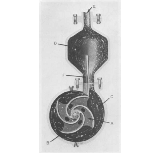
One such self-priming pump is illustrated in Figure 10.An open impeller (A) rotates in
a volute casing (B), discharging the pumped liquid through passage C into the reservoir
(D). When the pump starts, the trapped liquid carries entrained air bubbles from the suc-
tion to the discharge chamber. There, the air separates from the liquid and escapes,
FIGURE 10 Self-priming pump with recirculation at discharge (Flowserve Corporation)
2.464 CHAPTER TWO
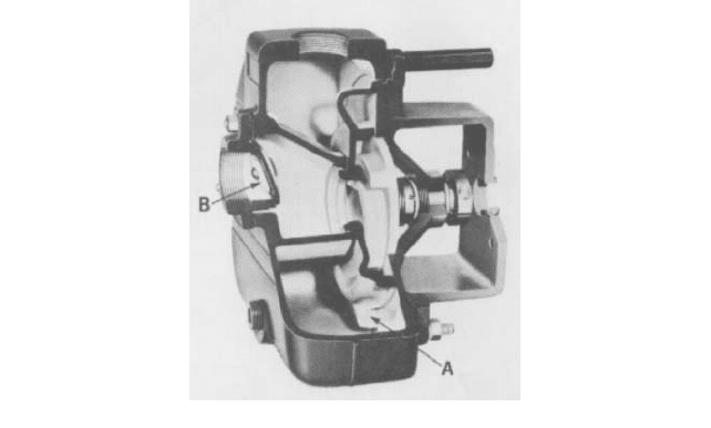
FIGURE 11 Self-priming pump with recirculation at discharge (Peabody Barnes)
whereas the liquid in the reservoir returns to the impeller through the recirculation port
(F), reenters the impeller and, after mixing once more with air bubbles, is discharged
through passage C. This operation is repeated continuously until all the air in the suction
line has been expelled. After the pump is primed, a uniform pressure distribution is estab-
lished around the impeller, preventing further recirculation. From this moment on, the liq-
uid is discharged into the reservoir bath at C and at F.
Figure 11 illustrates another form of self-priming pump with recirculation at the dis-
charge. In this arrangement, the return of the liquid to the impeller periphery takes place
through a communicating passage (A) located at the bottom of the pump casing. After the
pump is primed, liquid is delivered into the reservoir at the discharge both through its nor-
mal volute discharge and through port A. In the pump illustrated in Figure 11, a check
valve at the pump suction (B) acts to prevent the draining of the pump after it has been
stopped.
Regenerative Turbine Pumps Because these pumps can handle relatively large
amounts of gas, they are inherently self-priming as long as sufficient liquid remains in
the pump to seal the clearance between the suction and discharge passages. This condi-
tion is usually met by building a trap in the pump suction.
SPECIAL APPLICATIONS ______________________________________________
Systems for Sewage Pumps
A pump handling sewage or similar liquids containing
stringy material can be equipped with automatic priming, but special precautions must
be used to prevent carry-over of the liquid into the vacuum-producing device.
One approach is to use a tee on the suction line immediately adjacent to the pump suc-
tion nozzle, with a vertical riser mounted on the top outlet of the tee. This riser is blanked
at the top, thus forming a small tank. The top of the tank is vented to a vacuum system
through a solenoid valve.The solenoid valve in turn is controlled electrically through elec-
trodes located at different levels in the tank. The solenoid valve closes if the liquid reaches
the top electrode and opens if the liquid level falls below the level of the lower electrode.
Another solution permits the use of an automatic priming system with a separate
motor-driven vacuum pump controlled by a discharge-pressure-actuated pressure switch.
An inverted vertical loop is incorporated in the vacuum pump suction line to the pump
2.4 CENTRIFUGAL PUMP PRIMING 2.465
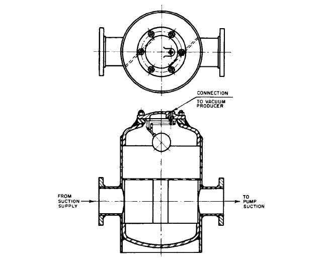
FIGURE 12 Air-separating chamber
being primed. This prevents the sewage from being carried over into the vacuum pump
because this pump shuts down before the liquid reaches the top of the loop.
Systems for Air-Charged Liquids Some types of liquid have considerable dissolved
gas that is liberated when the pump handles a suction lift. In such installations, an air-
separating tank (also called a priming tank or an air eliminator) should be used in the
suction line. One type (Figure 12) uses a float-operated vent valve to permit the with-
drawal of air or other gas. Another common arrangement uses a float valve mounted on
the side of the tank to directly control the starting and stopping of the vacuum pump.
Unless the air-separating tank is relatively large and the vacuum pump is not oversized,
there is danger of frequent starting and stopping of the vacuum pump in such a system.
When sand is present as an impurity in the liquid, the air-separating tank can be made
to also function as a sand trap.
Systems for Units Driven by Gasoline or Diesel Engines An automatic priming sys-
tem using motor-driven vacuum pumps can be used for centrifugal pumps driven by diesel
engines if a reliable source of electric power is available in the station. An auxiliary vac-
uum pump driven by a gasoline engine might be desirable for emergency use in case of
electric power failure. Alternatively, a direct-connected wet vacuum pump with controls
similar to those used in motor-driven automatically primed units is very satisfactory.
The choice of the priming device for a gasoline-engine centrifugal pump depends on the
size of the pump, the required frequency of priming, and the portability of the unit. Most
portable units are used for relatively low heads and small capacities, for use in pumping
out excavations and ditches, for example. Self-priming pumps of various types are most
satisfactory for this service and are preferable to regular centrifugal pumps.
It is possible to utilize the vacuum in the intake manifold of a gasoline engine as a
means of priming or keeping the pump primed. The rate at which the air can be drawn

2.466 CHAPTER TWO
FIGURE 13 Priming valve with liquid level control switch (Apco/Valve and Primer)
from the pump in this manner is relatively low, so many of these units use foot valves.
They are initially primed by filling the pump manually. Provision must be made to prevent
liquid from being drawn over into the manifold.
TIME REQUIRED FOR PRIMING_________________________________________
The time required to prime a pump with a vacuum-producing device depends on (1) the
total volume to be exhausted, (2) the initial and final vacuums, and (3) the capacity of the
vacuum-producing device over the range of vacuums that will exist during the priming
cycle. The calculations for determining the time necessary to prime a pump are compli-
cated. To permit close approximations, jet primers are usually rated in net capacity for var-
ious lifts. It is necessary to divide the volume to be exhausted by the rating to obtain the
approximate priming time. Unless such a simplified method is available, the selection of
the size of a primer is best left to the vendor of the equipment.
Central automatic priming systems are usually rated for the total volume to be kept
primed. The time initially required to prime each unit served by the central system is not
usually considered, as the basic function of the system is to keep the pumps primed and
in operating condition at all times.
PREVENTION OF UNPRIMED OPERATION _______________________________
Various controls may be used to prevent the operation of a pump when it is unprimed.
These controls depend upon the type of priming system used. For many installations, a
form of float switch in a chamber connected with the suction line is used. If the level in the
chamber is above the impeller eye of the pump, the float switch control allows the pump
to operate. If the liquid falls below a safe level, the float switch acts through the control to
stop the pump, to prevent its being started, to sound an alarm, or to light a warning lamp.
Such a valve and switch are illustrated in Figure 13.