Pump Handbook by Igor J. Karassik, Joseph P. Messina, Paul Cooper, Charles C. Heald - 3rd edition
Подождите немного. Документ загружается.

3.1 POWER PUMP THEORY 3.11
TABLE 7 Industry terms for the number of plungers or pistons
Number Term
1 Simplex
2 Duplex
3 Triplex
4 Quadruplex
5 Quintuplex
6 Sextuplex
7 Septuplex
9 Nonuplex
FIGURE 6 The discharge rate for a single double-acting pump (Flowserve Corporation)
The acceleration and velocity of the plunger or piston will determine the rate that the
fluid is discharged from the cylinder. The approximate velocity of the plunger or piston is
The approximate acceleration of the plunger or piston is
The momentary rate of discharge capacity is the cross-sectional area A of the plunger or
piston times velocity:
For single-acting plunger or piston
For double-acting piston
The total discharge Q is equal to ALS ¿, where S ¿ is the number of effective strokes in
a given time. The quantity Q is the area of the curve, the mean height of which is
where S¿¿ is the number of strokes per second and t is time in seconds.
Figures 6 and 7 show discharge rates for two types of pumps. Tables 8 and 9 show how
variations from the mean are related to the change in the number of plungers with a C of
Total Q>t ALS'>t ALS''
A a 0.785 1D
2
d
2
2
A 0.785 D
2
Cp
d
2
x
dt
2
r acos u
cos 2u
C
bv
2
S
dx
dt
r asin u
sin 2u
2C
bv
FIGURE 7 The discharge rate for a triplex single acting pump (Flowserve Corporation)
3.12 CHAPTER THREE
TABLE 8 The effect of the number of plungers on variations in capacity from the
mean (C is approx. 6:1)
Number of % % Total Plunger
Type Plungers Above Mean Below Mean % Phase
Duplex 2 24 22 46 180 deg.
Triplex 3 6 17 23 120 deg.
Quadruplex 4 11 22 33 90 deg.
Quintaplex 5 2 5 7 72 deg.
Sextuplex 6 5 9 14 60 deg.
Septuplex 7 1 3 4 51.5 deg.
Nonuplex 9 1 2 3 40 deg.
TABLE 9 The effect of change in C on variations in
capacity from the mean for a triplex pump
C % Above Mean % Below Mean Total %
4:1 8.2 20.0 28.2
5:1 7.6 17.6 25.2
6:1 6.9 16.1 23.0
7:1 6.4 15.2 21.6
FIGURE 8 Force balance of a typical valve
approximately 6:1. This shows that pumps with an even number of cylinders have a higher
flow variation than pumps with an odd number of cylinders. Table 9 shows the variations
in a triplex with changes in C L/R.
Valves A pump valve in its simplest form is a free-moving plug that is opened when the
force of the liquid below the valve exceeds the force of the liquid above it. When the force
above the valve becomes greater than the lower, the plug closes and forms an effective seal
to fluid “backflow” and pressure loss. If the valve does not perform this function efficiently,
the performance of the pump can be degraded to the point where no flow is produced.
A valve will be in equilibrium when the forces above and below the valve are balanced
(see Figure 8):
where P the pressure below the valve
A the area below the valve exposed to P
Equilibrium P
1
A
1
P
2
A
2
S
f
M
3.1 POWER PUMP THEORY 3.13
TABLE 10 Types of valves and their applications (Flowserve Corporation)
P the pressure above the valve
A the area above the valve exposed to P
S
f
the force of the valve spring ( if any)
M the mass of the valve and half the mass of the spring
The significance of this simple equation becomes apparent when you remember that
the valve is operating in a dynamic environment of constantly changing pressures in a
time frame that is measured in tenths of a second. Add to that the requirement that the
valve must pass a volume of fluid in each opening cycle with minimal pressure drop, and
it becomes clear that the pump valve is the most critical component in the fluid end in
terms of pump operability.
The pump designer will size the valves to provide a flow area, called the spill area, that
prevents pre-established velocity limits from being exceeded. The spill area of various
valve types is given in Table 10. The velocity of the fluid flowing through the spill area is
called the spill velocity, V, shown in Table 11:
TABLE 11 Valve spill velocities
Valve Spill velocity, ft/s (m/s)
Clean liquid suction valve 3-8 (0.9-2.4)
Clean liquid discharge valve 6-20 (1.8-6)
Slurry suction and discharge valve 6-12 (1.8-3.7)
3.14 CHAPTER THREE
In USCS units
In SI units
The quantity 0.642 (555.6) is used because all the liquid passes through the valve in
half the stroke.
Valve Dynamics Valve dynamics is the mechanical response of the valve to the changes
of pressure across the valve. Using a suction valve as an example, the valve starts its cycle
when the valve is closed and the plunger is at the start of its suction stroke (maximum
insertion into the cylinder). As the plunger starts withdrawing from the cylinder, the inter-
nal volume in the cylinder starts to increase. This increasing volume results in decreas-
ing cylinder pressure that, in turn, hydraulically unbalances the valve and the valve
begins to open. There is usually a slight lag in the valve opening versus the start of the
plunger motion of about 5 to 20 degrees of crankshaft rotation. Traditionally, the opening
valve lag is attributed solely to the inertia required to set the valve in motion and the pre-
load of the valve spring. In the last few years, the theory of valve stiction has been pro-
posed as an additional cause of valve opening lag.
Valve stiction, as the name implies, can be an additional force to overcome when the
valve is trying to lift off its seat. One version of the theory is that a cohesive force exists
between the fluid molecules and the sealing surfaces of the valve and seat. This can be
demonstrated by trying to separate two wet, highly machined plates. The second stiction
theory focuses on possible fluid dynamic conditions that may occur as fluid starts to flow
across the valve seat. Valve seats do not have “knife edge” sealing surfaces; they have a
width that distributes the stresses in the valve and seat. The stiction theory postulates
that the flow of fluid from the smaller area at the center of the seat to the larger area
around the seat causes a pressure drop across the seat. The pressure drop is the result of
the radial divergence of the fluid and is strong enough to momentarily prevent the valve
from opening. Extreme cases have even resulted in a circumferential ring of cavitation
located at the center of the sealing areas of the seat and valve.
Field testing valves with special grooves and radial slots in the sealing face has proven
successful in reducing stiction and opening valve lag in some cases. Narrowing the seal-
ing faces may also prove effective, although part life may decrease due to increased stress
and decreased wear area. Additional computer modeling and testing is required before the
stiction theory can be completely validated.
As the valve continues to open, the spill area increases proportionally. It must be
remembered that fluid is now flowing through the valve at an increasing rate while try-
ing to fill the expanding cylinder volume created by the plunger withdrawal. Ideally, the
motion of the valve will exactly correspond to the flow rate of the fluid through the valve,
and the valve follows a smooth trajectory to a full open position (see Figure 9).
This idyllic situation only occurs in very slow running pumps that are fitted with over-
sized valves. In modern higher speed pumps, the valve often accelerates at a rate fast
enough to create a spill area greater than that required to maintain a constant flow veloc-
ity. At this point, the valve motion momentarily stops, and the valve may even start to
close before the fluid flow once again matches the spill area. The valve then returns to the
smooth trajectory until the maximum valve lift occurs.
After the plunger passes the mid point of its stroke, it starts decelerating. The flow of
fluid through the valve is high enough to start to build pressure in the cylinder and unbal-
ance the valve and start the valve closing. The valve spring has reached its maximum com-
pression and, if properly designed, will help accelerate the valve back toward the seat.
When the plunger reaches the end of the suction stroke, the valve should also be closing.
The amount of crankshaft rotation that occurs between the time when the plunger reaches
the end of its stroke and when the valve is completely closed is called the delayed valve
closing and is normally 2 to 12 degrees of crank rotation. Although a delayed valve open-
ing may have little effect on overall pump performance, a delayed valve closing certainly
will. A valve that is partially open when the plunger reverses direction will result in back-
flow. Backflow, as the name implies, is the reverse flow of fluid back across the valve and
results in lower pump volumetric efficiency.
V 1m>s2 m
3
>h through valve 555.6>spill area of the valve, mm
2
V 1ft>sec2 gpm through the valve 0.642>spill area of the valve, in
2
3.1 POWER PUMP THEORY 3.15
FIGURE 9 Valve lift versus crank angle (in 2.54 cm)
FIGURE 10 Valve lift versus crank angle for a valve with a mechanical stop (in 2.54 cm)
Many pump valves are designed with mechanical limits to the distance that the valve
is allowed to open or lift. This is normally done to avoid overstressing the valve spring and
to minimize the overall height of the valve assembly. Valve motion for a valve designed
with a mechanical stop is shown in Figure 10.Another advantage of this design is that the
valve does not have to travel as far during its closing cycle, compared to valves with no
mechanical limits. The disadvantage is the potential for impact damage to the valve if it
strikes the stop with excessive force.
3.16 CHAPTER THREE
The importance of valve mass to overall valve dynamics has been the subject of much
debate among pump designers over the years.There is no question that the mass of the valve
must be overcome in order to open the valve.Test data is also available that shows no appre-
ciable difference in the performance of pumps fitted with hollow ball valves versus identical
pumps with solid ball valves.This apparent contradiction can be explained by studying valve
acceleration at various parts of the valve cycle using advanced computer modeling.
It has already been explained above why a valve can hesitate, or stop opening, during
the opening portion of its cycle. It’s also been stated that when the valve spill area is large
enough to establish a hydraulic balance, the valve will stop opening. What actually occurs
is the valve starts decelerating as it comes closer to hydraulic equilibrium. If the valve is
properly designed, it will contact its mechanical stop just as its acceleration/deceleration
is very low. In that case, the valve mass has little significance on the impact force of the
valve on the stop. The same holds true of the impact force of the valve on the seat as it
closes. If the valve is properly designed, a 62-lb (28 kg) solid ball valve operating at 100
cycles per minute can strike the seat with less than 20 lbs (9 kg) of force.
Although pump valves operate in a liquid medium, the shape of the valve is not an
important design consideration for most applications. The relatively small distance that a
valve travels is not sufficient for the fluid dynamics of a shape to have a measurable effect
on valve dynamics. The only exception to this is valves in pumps handling high-viscosity
liquids. For these applications, the ball valve, often spring-loaded, has proven to reduce
closing valve lag and increase volumetric efficiency better than any other type of valve.
The most critical component in the optimization of valve dynamics is the valve spring.The
pump designer normally selects a valve spring that will exert a certain amount of “pre-load”
on the valve when it is closed.This pre-load helps the valve to close smoothly on the seat and
avoid rebound (and possible backflow). Too high a preload in the suction valve may result in
higher net positive suction head required (NPSHR). In the discharge valve, excessive preload
can cause abnormally high pressure spikes in the fluid cylinder just before the valve opens.
The other valve spring design criterion is the spring rate. Every compression spring
develops a predetermined resistance per unit length. This value is expressed in pounds per
inch (kg per cm).As the valve is opening, the increasing spring force helps the valve obtain
hydraulic balance faster. It also helps to limit the impact force of the valve on the stop. At
the start of the closing cycle, the stored energy in the compressed spring helps the valve
respond faster to the pressure changes in the fluid cylinder as the plunger starts to decel-
erate. Again, if the spring is properly designed, the closing valve lag will be minimized.
No published guidelines exist for the proper amount of valve spring pre-load or spring
rate. Most pump designers use proprietary values, generated through a combination of in-
house and field testing. However, although these values produce low NPSHR and high vol-
umetric efficiency in most cases, the valve dynamics may not be close to being optimized.
It should also come as no surprise that pumps fitted with “off-the-shelf” commercially
available valves do not operate as well as pumps having optimized valve dynamics.
With the recent advent of advanced computer modeling of pump valves, it is now pos-
sible to optimize valve dynamics for a specific set of pump operating parameters. We may
also see valve designs in the near future having variable rate valve springs, hydraulic
dampening, and mechanisms that induce rotation as the valve opens and closes.
POWER END THEORY_________________________________________________
The power end or drive end of a power pump consists of a crankshaft, connecting rods,
crossheads, and bearings, all housed in a rigid structure referred to as the frame. Details
of the design and construction of these components are covered in Section 3.2, “Power
Pump Design and Construction.” The slider-crank mechanism that converts rotational
driving energy to the reciprocating motion that actuates the pistons or plungers can be
found in reciprocating gas compressors, automotive engines, and stationary and marine
engines. However, the stress loading pattern of power pump components is unique to this
type of mechanism.
3.1 POWER PUMP THEORY 3.17
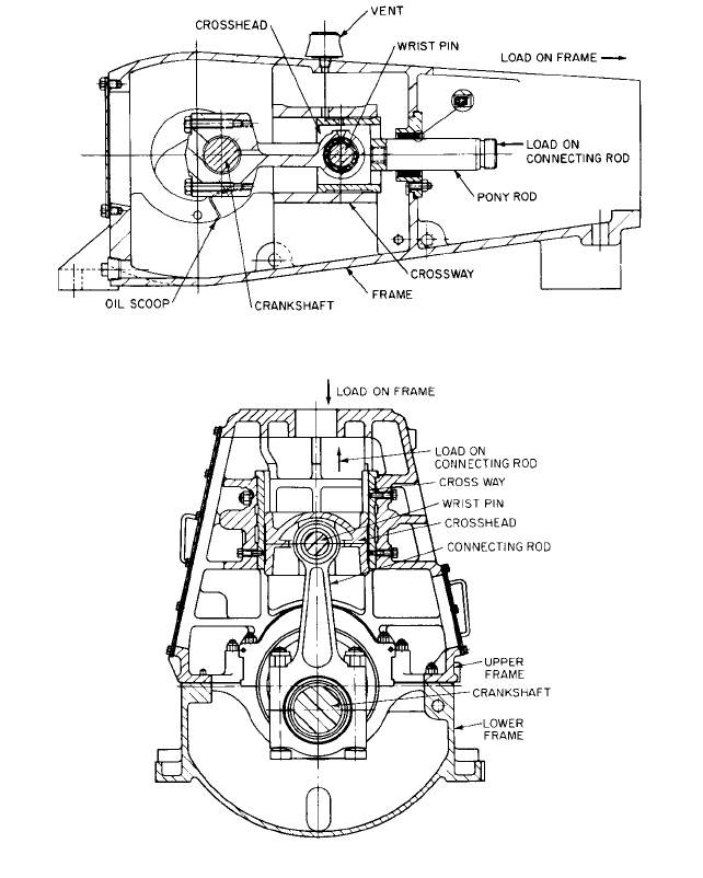
FIGURE 11 Power end, horizontal pump (Flowserve Corporation)
FIGURE 12 Power end, vertical pump (Flowserve Corporation)
Applying Rod Load to the Power End As stated earlier, the loading on the power end
is called the rod load and is the product of the area of the plunger multiplied by the max-
imum discharge pressure. In a gas compressor or engine, this loading increases over 90
to 180 degrees of crank rotation before maximum loading is reached. In a power pump,
the maximum loading is reached in less than 30 degrees of crank rotation due to the rel-
ative incompressibility of the pumpage. Since this loading cycle is repeated with each
plunger stroke, the actual loading resembles a shock load more than a simple cyclic fatigue
load. The design criteria for the stressed components of the power end must therefore
include the material’s capability to absorb shock loads and overall safety factors greater
than 3:1.
Another critical factor in the capability of the power-end components to handle the rod
load is how the load is applied. Figures 11 and 12 show the direction of the load on the

3.18 CHAPTER THREE
frame and connecting rod for two different power end configurations. On vertical pumps
with outboard packed stuffing boxes, the frame is in compression and the crosshead and
connection rod are in tension. With horizontal, single-acting pumps, the frame is in ten-
sion, and the crosshead and connecting rod are in compression. The material selection and
factors of safety must be altered accordingly.
Liquid Separation from the Plunger It has already been explained that fluid flows
through the suction valve (and suction manifold and related piping) to fill the increasing
cylinder volume caused by the withdrawal of the plunger. If the plunger accelerates faster
than the flow of incoming liquid, the liquid will lose contact or separate from the plunger.
The void that forms will be at a pressure lower than anywhere else in the cylinder. If the
pumpage contains entrained gas, the gas may come out of a solution in this low-pressure
area. The gas bubbles, when recompressed later in the plunger stroke, can cause cavita-
tion damage to the plunger and surrounding cylinder.
The geometry of the slider-crank mechanism affects the point at which liquid separa-
tion occurs. As the ratio of the connecting rod length to the crank radius increases, the
pump speed at which liquid separation occurs will decrease. Since liquid separation can be
the determining factor in a pump’s NPSHR, the pump designer must carefully evaluate
the slider-crank geometry in order to optimize the pump’s hydraulic performance. The
pump speed at which water will separate from the end of the plunger can be calculated
from the following:
In USCS units:
In SI units:
where h
s
suction head, ft (m)
h
f
piping frictional loss, ft (m)
A
s
area of suction pipe, in
2
(mm
2
)
L length of connecting rod, centerline to centerline, ft (m)
R crank radius, ft (m)
l length of pipe where resistance to flow is to be measured, ft (m)
A
p
area of plunger, in
2
(mm
2
)
Unbalanced Forces Due to the relatively slow speed of a power pump, the inertia loads
of the rotating/reciprocating parts are low enough to avoid the vibration problems asso-
ciated with centrifugal pumps. For that reason, power pump crankshafts are not normally
balanced. However, when the power pump is coupled to a drive containing a high-speed
motor and gear reducer, a torsional analysis of the pump/drive unit may be required. For
this analysis, the unbalanced forces of the rotating and reciprocating pump components
can be calculated as follows:
Unbalanced Reciprocating Parts Force (F
rec
) Parts are typically about one-third of the
connecting rod weight (the crosshead, the crosshead bearing, the wrist pin, the pony rod,
and the plunger). Additional parts on vertical pumps include the pull rods, yoke, and
plunger nut.
where F
rec
reciprocating parts force, lb (N)
W weight of all reciprocating or rotating parts, lb (N)
F
rec
W
g
v
2
Racos u
R
L
cos ub
rpm 16.6
B
110.36 h
s
h
f
2A
s
LR3l 1l>LR24A
p
rpm 54.5
B
134 h
s
h
f
2A
s
LR3l 1l>LR24A
p

3.1 POWER PUMP THEORY 3.19
g 32.2 ft/s
2
(9.81 m/s
2
)
v (2p/60) n (n pump rpm)
R one-half of stroke, ft (m)
L length of connecting rod, centerline to centerline, ft (m)
u crank angle; usually maximum force is at u 0°, cos u 1
Unbalanced Rotating Parts Force (F
rot
) Parts are typically about two-thirds of the con-
necting rod weight, crank end bearing, and crankpin, where the variables are as above.
Mechanical Efficiency The mechanical efficiency of a single-acting power pump with-
out internal gears is typically 90 to 92%. Over half of the mechanical losses are due to the
frictional drag of the plungers through the packing. The remaining losses are from the
bearings, the crosshead-to-crosshead guide friction, and the extension rod-to-gland seal
friction. If these components are properly lubricated, very few power-end design options
are available that will produce a measurable increase in mechanical efficiency. Decreas-
ing the diameter of the plungers and minimizing the number of packing rings will result
in a small efficiency increase.
FURTHER READING __________________________________________________
American National Standard for Reciprocating Power Pumps for Nomenclature, Defini-
tions, Application and Operation, ANSI/HI 6.1-6.5-2000, Hydraulic Institute, Parsippany,
NJ www.pumps/org
Positive Displacement Pumps—Reciprocating, API Standard 674. 2nd Edition, 1994, The
American Petroleum Institute, Washington, D.C. www.api.org
Henshaw, T. L. Reciprocating Pumps. Van Norstrand Reinhold Company, Inc., New
York, 1987.
Miller, J. E. The Reciprocating Pump
—
Theory, Design and Use. John Wiley & Sons, Inc.,
New York, 1987.
F
rot
W
g
v
2
R

WILLIAM K. CHAPLIS
FREDERIC W. BUSE
3.21
SECTION 3.2
POWER PUMP DESIGN
AND CONSTRUCTION
The power pump, as a piece of rotating equipment, would seem to have a great deal in com-
mon with a reciprocating gas compressor or diesel or gas engine. All have crankshafts,
bearings, connecting rods, and lubricating oil systems that use the pump frame as an oil
reservoir. All have a fluid or gas end that contains relatively high pressure and includes
some type of valving that enables the equipment to perform its required task.
Due to the unique operating characteristics of the power pump, very little design crite-
ria or construction details can be directly transferred from these other mechanisms.
Because of the high compressibility of most gases, the resulting cyclic loadings are applied
to the various rotating, reciprocating, and pressure-retaining components in a smoother
manner. Therefore, gas-driven or gas-pumping mechanisms can operate at speeds three or
four times higher than a reciprocating pump with good reliability and low vibration levels.
It has been said that a power pump has more in common with a jackhammer because
of the constant high-cycle shock loading that it must be designed to withstand. Therefore,
very conservative material selections, stress limits, and factors of safety have been estab-
lished by the pump designers for all continuous duty applications. Intermittent duty appli-
cations can be met using less stringent design criteria.
Seldom is a power pump designed for one specific application having one specific set of
operating conditions. Consequently, few pump designs are truly optimized. The best eco-
nomical approach has been to design a power end capable of accepting a number of fluid
ends, which in turn allows the pump to operate over a wide range of hydraulic conditions.
By using different plunger diameters for a specific operating pressure, the designer tries
to “load up” the power to its maximum continuous rod load rating while maintaining the
pump speed at a level just sufficient to provide the required flow rate.
A power pump has its cylinders operating in parallel with interconnecting suction and
discharge manifolds. Additional cylinders are sometimes added to a basic power-end
design in order to obtain higher flow rates. The most common examples of this approach
are the quintuplex pumps that have an 80-percent component interchangeability with