Pump Handbook by Igor J. Karassik, Joseph P. Messina, Paul Cooper, Charles C. Heald - 3rd edition
Подождите немного. Документ загружается.

2.416 CHAPTER TWO
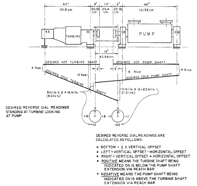
FIGURE 12 Alignment example of a turbine-driven boiler-feed pump with heat-rise data from the manufacturers
plotted to calculate the desired cold alignment
4. Acculign bench mark gauges (I. Essinger, Shell Oil)
5. Water-cooled probe stands (C. Jackson, Monsanto)
6. Instrumented coupling (for example, Indikon)
Refer to Reference 4 for more specific information on the above techniques.
After measurements have been made and actual misalignment is determined for the
hot running condition of the pump, the next step is to calculate the alignment correction
required between machines to bring them into alignment during operation. Trial-and-
error methods should be discouraged. Plotting actual shaft positions to scale allows one to
graphically measure the required cold alignment corrections. Other methods
—
for exam-
ple, those that can best be carried out with the aid of a programmable calculator
—
quickly
and accurately calculate vertical, horizontal. inboard or outboard changes in machine posi-
tions to accomplish the correct cold alignment. See Reference 11 for a calculator program
for both reverse dial and face and rim methods.
Offered here are a graphical procedure and an example for obtaining the desired align-
ment between a pump and driver for a case where the thermal growth has been estimated
and a calculated cold alignment is desired to achieve the final alignment during operation.
The example is illustrated in Figure 12. Consider a steam-turbine-driven boiler-feed
pump that has the following heat rise predictions by the manufacturers: steam end 0.002
in (0.051 mm), exhaust end 0.012 in (0.305 mm), pump inboard support 0.006 in
2.3.3 CENTRIFUGAL PUMP MECHANICAL PERFORMANCE 2.417
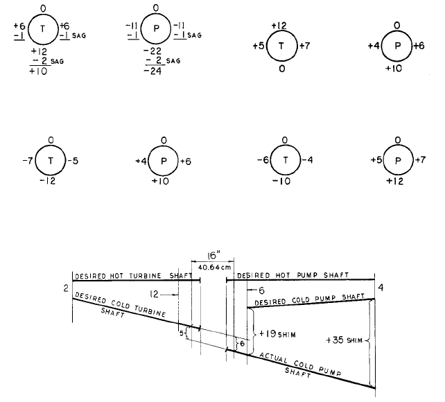
FIGURE 13 Desired dial indicator readings
corrected for indicator bar sag
FIGURE 14 Actual alignment readings
FIGURE 15 Dial readings corrected to position zero
at top
FIGURE 16 Actual alignment readings corrected for
indicator bar sag
(0.152 mm), and outboard bearing 0.004 in (0.102 mm). The horizontal length is laid on a
graph with 1 div. 1 in (25.4 mm). The vertical movement plots are laid out with 1 div.
0.001 in (1 mil; 0.0254 mm).
Based on 0.001-in (0.0254-mm) sag (see Figure 19), the field readings needed to meet
the above absolute requirements are shown in Figure 13.
The actual cold alignment is checked, and the reverse dial readings are as recorded in
Figure 14. There are 0.125-in (3.175-mm) shims under all support feet. It is decided to
move the pump rather than the turbine, and therefore the correct cold position of the
pump must be calculated.
To correct the turbine dial readings to position zero at the top, simply add 12 to all
four turbine readings (Figure 15). To correct for sag (see Figure 19 for explanation), sub-
tract 1 from the left and right readings and 2 from the bottom reading (Figure 16). Finally,
plot the absolute shaft positions on graph paper, leaving the turbine “in place,” so to speak,
thereby determining two points across the 16-in (40.64-cm) indicator span to define where
the pump shaft lies with respect to the turbine (Figure 17).
To plot the horizontal corrections, reduce the final horizontal readings only to zero on
the least numerical reading, by adding 4 to the turbine readings and 5 to the pump read-
ing, as shown in Figure 18.
Dial indicator readings can be in metric units and the scale in centimeters rather than
inches. A scale of between 500:1 and 1000:1 is suggested. A 1000:1 scale is in use here (hor-
izontal scale equals 1000 times vertical scale).
FIGURE 17 Plot of absolute vertical shaft positions. It can be seen from the graph that a 0.019-in (0.483-mm)
shim is required to raise the inboard end of the pump and a 0.035-in (0.889-mm) shim is required to raise the
outboard end of the pump to compensate properly for thermal growth
2.418 CHAPTER TWO
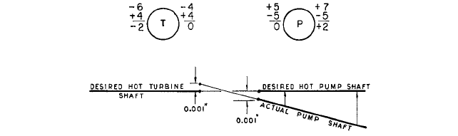
FIGURE 18 Required horizontal corrections
As shown in Figure 12, the driver and pump are purposely misaligned so actual oper-
ating temperatures will put the two shafts within acceptable limits.The acceptable limits
for pump final alignment are 0.001 in/in (0.025 mm/mm) of coupling flex plane separation.
If a spacer coupling is 5 in (13 cm) between flex planes on the flexible coupling, the shafts
must be within 0.005 in (0.127 mm) vertical or horizontal offset. Pure angular misalign-
ment in one plane is not desired, as it reduces the tolerance by 2:1 for gear couplings (dry
coupling would have severe fatigue in one flex plane). The above limits should be reduced
by one-half.
INSTALLATION SUGGESTIONS AND USE OF DIAL INDICATORS _____________
1. Nonferrous shim packs should be installed under all feet of the pump and driver, par-
ticularly when installing a new pump. The amount should be 0.125 to 0.250 in (3.175
to 6.35 mm) in no more than three pieces to start; for example, one 0.125-in
(3.175 mm) and two 0.0625-in (1.59-mm) full shims of stainless steel.
2. Motors have four feet generally, and any “soft foot” should be compensated first. A soft
foot is one that is shorter than the other two or three feet, a condition that puts a twist
or strain in the equipment. Simply place a dial indicator stem vertically against the
motor foot and release the hold-down bolts sequentially around the unit, recording
and retightening at each step. If a 0.002-in (0.050-mm) spring-up occurs on three feet,
for example, and 0.006 in (0.152 mm) occurs on the fourth foot, add 0.004 in (0.10 mm)
of shim to the fourth foot, eliminating the soft foot.
3. Provide low-sag tooling to reach over the coupling (coupling left in place) for reverse
indicator alignment. A 0.001- to 0.0015-in (0.025- to 0.038-mm) sag is easy to accom-
plish on indicator reach bars.
4. Let the indicator indicate on its own bracket or bracket pin, thus preventing any poor
surface condition of shaft or coupling from contributing to poor measurements.
5. Support the dial indicator weight on the motor or pump shaft so it does not contribute
to “reach bar” sag.
6. Do not overlook the fact that many times one can clamp to the shaft behind each cou-
pling hub and obtain more span and therefore better accuracy.
7. Record all data looking the same way down the unit; that is, top east, bottom, west or
top, north bottom, south or top, right bottom, left. It is suggested that the driver-pump
always be viewed from the driver end.
8. Turn the shafts in the direction they normally turn and approach the 90° points in
a precise manner (do not back up and introduce backlash errors).Turning in the nor-
mal direction is good training because, on gear units, it reduces helix angle lift
errors.
2.3.3 CENTRIFUGAL PUMP MECHANICAL PERFORMANCE 2.419
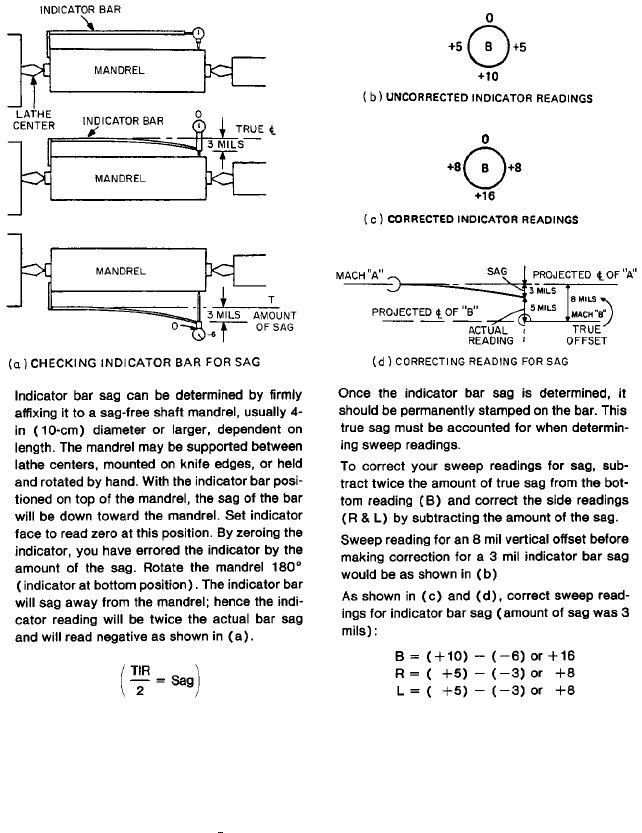
FIGURE 19A through D Illustrative procedure to determine the amount of sag in an indicator bar (bracket)
(Courtesy Reference 3)
9. If the motor can be turned down from the end opposite the end from which the mea-
surements are taken, do so. Regardless, always release the strap wrench or spanner
bar before recording each -point reading.
10. Obtain center zero dial indicators or revolution counter indicators or carefully note all
indicator movements with a mirror to assure, for example, that 0.090 in was not really
0.010 in.The algebraic sum of horizontal and vertical readings should be near equal.
INSTRUMENTS FOR VIBRATION ANALYSIS_______________________________
One fact about end-suction and between-bearing pumps is that external visual evidence
of mechanical problems is very limited. Only three gauges for mechanical trouble exist:
temperature, vibration, and sound.
1
4
2.420 CHAPTER TWO
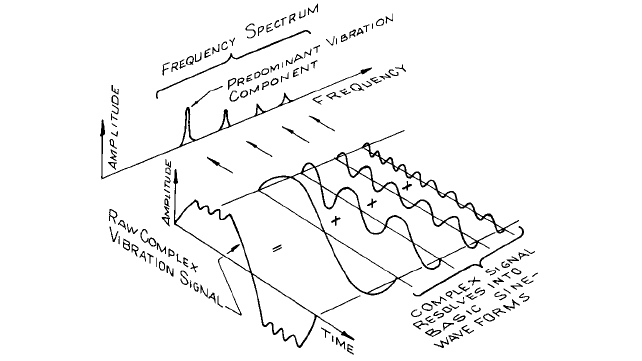
FIGURE 20 Complex vibration signal resolves into sine wave spectrum
It is normal for a machine to vibrate at some level; such vibrations are caused by man-
ufacturing defects, design limits of the pump, casting irregularities, less than optimum
application, and a maintenance/installation problem. When the velocity vibration level
starts to increase 0.1 in/s (2.5 mm/s) zero to peak (0-P) above the “as new installed level,”
the vibration should be analyzed to determine the possible sources of the mechanical
and/or hydraulic problem. Several mechanical and/or hydraulic problems may be produc-
ing, for instance, the 1 running speed frequency vibration. The key in using vibration to
define the mechanical and/or hydraulic problems is to determine the frequency at which
the vibration occurs. Vibration amplitude is also an important factor because it indicates
the severity of the vibration. Field vibration data are normally a complex vibration wave-
form. By using a tunable analyzer, the complex vibration signal, as shown in Figure 20,
can be filtered or tuned into its basic frequency components; that is, all complex signals are
summations of the harmonics and subharmonics 1, 0.5,6,30, and so on. By com-
paring these filtered components of the complexed vibration signal with an analysis chart
and some common-sense experience, probable causes of the vibration can be listed.
The first step toward resolving the vibration problem is to convert the mechanical
movement to an equivalent electrical signal so it can be filtered and measured.
Often used analyzer systems are
1. A turbine ac-battery-powered analyzer with strobe light, providing amplitude,
frequency, and phase. A plotter accessory can also be attached for copies of the data.
2. A small battery-powered, internally driven, tunable analyzer with a built-in plotter
using an accelerometer or velocity sensor.
3. A spectrum analyzer, ac powered, that receives the signal directly from a vibration
transducer or the recorded signal from a battery-powered four-channel FM/AM
cassette tape recorder.
For startup or where the problem is tougher, one can add
1. Eight-channel FM tape recorder
2. Four-channel oscilloscope with blanking and time display
3. Tracking filter displaying revolutions per minute, amplitude, and phase, capable of
tracking runup/rundown data
2.3.3 CENTRIFUGAL PUMP MECHANICAL PERFORMANCE 2.421
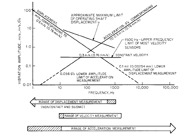
FIGURE 21 Limitations on machinery vibration analysis systems and transducers (mils 0.0254 = mm; in/s
25.4 = mm/s) (Reference 10)
Provisions should be made for the use of all types of sensors, as there are advantages
in each. As more complex problems continue to appear, tunable analyzers with a sensor
are not just a requirement but a necessity in any maintenance reliability program. The
choice of a displacement sensor (eddy current probe), velocity or seismic sensor, or an
accelerometer depends on the frequency range to be analyzed and the type of pumping
equipment. There is no one vibration sensor for all jobs.
Of the three types of vibration measurements, acceleration and displacement are
dependent on frequency and velocity is independent of frequency. Most engineers and
technicians select a measurement that is independent of frequency for a datum to judge
the general health of new and used pumps. With the exception of low-speed pumps and
motors, 1750 rpm or less, unfiltered velocity and filtered velocity are used for most basic
data. Figure 21 shows the frequency relationships (log) versus output (log) of three differ-
ent measurement sensors with reference to a constant velocity of 0.3 in/s (7.6 mm/s). The
figure gives an overview of present sensor limits and shows that each sensor is like a win-
dow through which portions of the frequency spectrum may be observed. The figure also
shows that the accelerometer is the choice sensor at high frequency because it measures
the square of the frequency. The advantage of displacement at low frequencies is due to its
high output; the disadvantage of displacement at high frequencies is that the output sig-
nal will disappear into the background noise of most measuring systems.
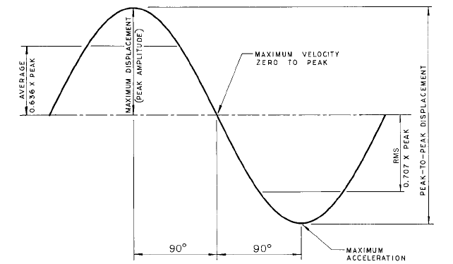
One should not confuse the measurement parameters (displacement, velocity, and
acceleration) with the sensors (eddy current probes for displacement, velocity sensors, and
accelerometers). The basic relationship of these measurement parameters with commonly
used units are shown on a simple sine wave in Figure 22.
Although the velocity sensor is not necessarily the best all-around type of sensor, it does
have the advantage of high self-generating output (up to 1000 ft [300 m] of cable), can be
mounted in any position, and is influenced only slightly (less than 5%) by transverse sen-
sitivity (side forces). The disadvantages are that the output signal below 600 cpm is sig-
nificantly nonlinear but can be corrected, the accuracy is limited at 8% to 1000 Hz, and
2.422 CHAPTER TWO
FIGURE 22 Basic relationship of measured parameters with a simple sinusoidal vibration
the sensor will most likely have problems in one to two years when mounted in field appli-
cations where vibration is high, especially vane passing frequencies.
The piezoelectric accelerometer is a very light and compact sensor that measures vibra-
tion using a mass mounted on a piezoelectric crystal. Its output is low and requires a charge
amplifier in the lead even with very short leads. The accelerometer is small and can be
mounted virtually anywhere; it has a 1 to 3% influence factor from transverse side forces.A
good rule of thumb on the usable frequency range is one-fifth to one-third of the resonant fre-
quency. The disadvantages are that the sensor is sensitive to mounting torque, although
stud mount is the best method to mount accelerometers.A lot of data are produced, of which
some may be the data from an excited accelerometer resonance or cable noise.An impedance
matching device can be built into the accelerometer for use at temperatures below 250°F
(120°C), and cable noise can be greatly reduced with the voltage and charge sensitivity
greatly improved; for example, 100 mV/g and 50 to 100 pC/g (where g number of acceler-
ations of gravity). For higher temperatures, the accelerometer will need a separate charge
amplifier and may need heat insulation, such as MICA wafers (refer to API 678,dated 1981).
Most so-called ultrasonic analyzers use the accelerometer as a structural microphone.
Many have chosen a carrier frequency in the megahertz range to improve the signal-to-
noise ratio and make characteristic high-frequency patterns. Most of these systems are
still in the development stage.
Techniques for Taking Data The second most important part of a vibration analysis
program is the type of data taken and the techniques used to take the data. The purpose
of taking vibration data on a pump is to either perform an analysis because someone
noticed a noise or increased vibration level, or as a part of a periodic preventative main-
tenance program. It has been proven from experience that the velocity measurement is
the best method for determining acceptable levels of centrifugal pump vibration. This is
not to say that displacement and acceleration are not measures of vibration severity; they
are, but it is necessary to know the frequency of the vibration. Displacement is preferred
by a few for frequencies less than 6000 cpm. Accelerometers matched with analyzers can
be purchased with signal integration that will give reliable readings in velocity in the
3000- to 60,000-cpm range. For readings above 60,000 cpm, the sensor would generally be
an accelerometer reading in g’s, peak or integrated to read velocity zero to peak or 0-P.
Vibration amplitude is an important parameter because it indicates the approximate
severity of the dynamic stress levels in the pump. Experience has shown that the shaft

2.3.3 CENTRIFUGAL PUMP MECHANICAL PERFORMANCE 2.423
bearings and seal will probably fail in a pump with a velocity reading of 0.5 in/s (13 mm/s)
0-P. Also, catastrophic failures will probably occur when a pump is at 1 in/s (2.5 mm/s) 0-P.
Pumps with velocity readings of 0.05 to 0.15 in/s (1.3 to 3.8 mm/s) 0-P, will perform well
mechanically. Vibration readings are taken in the horizontal and vertical planes on the
bearing housing of horizontal-shaft pumps.
To have a worthwhile maintenance reliability program with pumps, vibration readings
must be recorded regularly (that is, monthly).This can range from a trend plotting of unfil-
tered vibration to a full vibration analysis using a real-time analyzer to generate the fre-
quency spectrum. A standard method used by many companies consists of taping pump
vibrations with a battery-powered cassette recorder using a velocity sensor. Readings can
then be processed through a real-time analyzer and recorded on an XYY¿ plotter. The best
application of this method is during startup and repair evaluation.
As an alternate method, a spectrum analyzer/plotter that produces a spectrum on a
4 in 6 in (l0 mm 15 mm) card with a frequency plot versus amplitude can be used.
This procedure has in some installations detected and corrected 95% of the mechanical
problems before failure. Experience has shown that had unfiltered displacement readings
been taken, only 60 to 70% of the mechanical problems would have been observed. During
these recordings, emphasis should be placed on the change in vibration levels, which is a
better indication of a mechanical problem than absolute vibration.
One of the best pieces of data available for the pump’s equipment file is a vibration
record taken during the manufacturer’s test or during water batching or commissioning.
It is advisable to request a witness performance test on key or critical pumps.The purpose
of this test is to assure mechanical reliability along with performance.
The manufacturer should be asked about the availability and type of vibration analy-
sis equipment and sensors. Regardless of the instruments used, the vibration data sheet
for the tested pump should have a sketch of where all vibration points were taken. The
manufacturer should also supply a complete mechanical description of the number of
impeller vanes, number of casing volute cutwaters or diffuser vanes, type of coupling,
length of coupling spacer, and so on.
There are several different methods for taking periodic vibration data on pumps:
1. Using a handheld battery-powered velocity probe/readout, a machinist or operator
logs unfiltered readings taken at one or two points on the bearing housing. When the
reading reaches 0.3 to 0.5 in/s (8 to 13 mm/s) 0-P, the pump is pulled for maintenance.
Readings are usually taken every two weeks.
2. Vibration points in the vertical, horizontal, and axial directions are recorded on a tab-
ulated chart in unfiltered and filtered velocity at the various peak amplitudes, using
a battery-powered tunable analyzer with a velocity sensor.
3. Vibrations in the vertical, horizontal, and axial direction are taken at each bearing,
using a velocity sensor. The signal is recorded on a tape recorder, preferably a battery-
powered FM/AM cassette. These data are then processed through a real-time ana-
lyzer. A spectrum hard copy is made on an XYY¿ plotter of velocity versus frequency.
4. Key vibration points are fed directly from a velocity sensor or an accelerometer/charge
amplifier through a long extension cable to a safe area, where a real-time analyzer
processes the signal into a velocity versus frequency spectrum or a g’s (acceleration)
versus frequency spectrum. Hard copies for records are made on a XYY¿ plotter. This
method requires two technicians with radios.
The most accurate are methods 3 and 4. The most costly to run in workerhours per point
is method 2.The least accurate is, of course, method 1, but it is a popular screening technique.
Use of Vibration Sensors The use of a handheld velocity sensor with an aluminum
extension rod or a light-duty vise grip with the probe mounted on the top of the grip has
produced some high and misleading vibration readings because of extension resonances.
For instance, the vise grip should not be used because of a 5000-cpm resonance. A 9-in
(23 cm) long by -in (0.95-cm) diameter extension to the velocity pickup should not be used
above 16,000 cpm. The approximate axial natural frequency in cycles per minute for a rod
extension from the probe, in tension and compression, can be expressed as
3
8

2.424 CHAPTER TWO
°For aluminumm, E 10.3 10
6
lb/in
2
(71 10
6
kPa). For steel, E 30 10
6
lb/in
2
(207 10
6
kPa)
in USCS units
in SI units
where W pickup weight (force), lb (N)
L length of rod, in (m)
A cross-sectional area of rod, in
2
(m
2
)
E modulus of elasticity of rod,° lb/in
2
(kPa)
Use of attachments above these listed frequencies will produce a higher amplitude.
The best and simplest method of holding a velocity probe to a pump is a two-bar mag-
netic holder on the end of a velocity probe. Proper cleaning and some paint removal are gen-
erally necessary for good attachment. Periodic wiping of the magnetic bar to remove iron
filings is also necessary. After mounting the probe, give it a light twist and a rocking motion;
if it twists easily or rocks, change locations or reclean the surface. This location should be
marked and future readings taken on the same spot; otherwise, the trend plots will vary.
If there is a concern about an extension or magnetic holder resonance, test this by hold-
ing the sensor, without the extension or magnetic holder, directly to a reasonably flat spot and
noting any differences. Holding the sensor on a flat spot is generally safe up to 60,000 cpm.
When measuring vibration on an electric motor, there is always the possibility of false
readings at 60 and/or 120 Hz due to electrical induction by the motor. This can be checked
by two methods:
1. Hold the sensor by its cord and move it toward the motor, noting any increase in
amplitude.
2. Using a two-channel oscilloscope, trigger the filtered signal against line voltage. In-
phase signals mean the vibration is electrically induced.
For field use, one usually does not have to contend with temperatures above 250°F
(120°C) direct to the sensor; thus, accelerometers with built-in impedance matching
devices can be used and 100 mV/g voltage sensitivities can be obtained and transmitted
300 ft (90 m) if necessary. If the frequency range is low, and it is for pumps, a charge sen-
sitivity in the order of 100 pC/g can also be obtained.
Techniques for Taking Preliminary Vibration Readings Some key points to remem-
ber before you start your analysis of the vibration problem:
1. Do not reach a decision on what the problem is before you record and analyze the data.
By deciding too quickly what the problem is, you will most likely neglect other
important factors.
2. Before you take the data, take time to review maintenance logs, talk with the area
mechanic and operator, and make notes on the following:
a. Are there any unusual sounds (cavitation, bearings, and so on)?
b. Is there any movement in the discharge pressure gage?
c. What is the direction of rotation?
d. Are the flush and cooling lines lined up properly?
e. Is there any movement in the coupling shim pack?
f. Are there any foundation cracks?
g. Are pipe supports functioning properly?
h. Has a suction screen been installed?
f
n
946
B
AE
WL
f
n
188
B
AE
WL
2.3.3 CENTRIFUGAL PUMP MECHANICAL PERFORMANCE 2.425
i. What is the magnitude of the liquid velocity in the suction line?
j. Is the automatic oiler level adjusted correctly?
k. Where is the pump being operated?
l. What are the flow, suction, and discharge pressure?
m. Is the pump’s minimum flow bypass system in service?
n. Has the process changed?
o. What is the suction valve stem orientation?
p. Have there been any color changes in the paint?
q. Are there any loose parts, including the coupling guard?
r. Determine the color and feel of the oil (if possible).
s. What is the bearing housing temperature?
t. How is the coupling guard attached (attachment to the bearing housing is poor
practice)?
You will be surprised how much this information aids in an analysis. Example:
you record a high 1 in the radial plane, low values of 2 and 5, and several
high-frequency components at about 0.15 in/s (4 mm/s) 0-P. The 1 could be a bent
shaft, loose coupling, plugged impeller, bad coupling unbalance, upper and lower
case halves misaligned, and a whole list of running frequencies symptoms. During
your review of maintenance logs, you noted that the impeller had been replaced
because there had been distillation column tray part damage. The next questions
you should ask are, “Did maintenance reinstall the suction screen?” (if not,
another tray part may have lodged in the impeller) and, “Was the impeller rebal-
anced after it was trimmed from maximum diameter?”
3. Do not try to interpret partial vibration readings for someone looking over your shoul-
der before you have even taken all the readings. Sit down in a quiet place with your
notes on installation and maintenance, a symptoms list, and a severity chart and then
make the analysis. Analysis is not a simple task, but with some experience you will
build confidence and it will become second nature.
VIBRATION DIAGNOSTICS_____________________________________________
Analysis Symptoms
The vibration severity chart and vibration identification chart are
guides, but experience, a set of procedures, and study of the literature will make diag-
nostics easier. To be effective, one must be thoroughly familiar with the machinery’s inter-
nal construction, installation, and basic control system. Both mechanical and hydraulic
mechanisms can produce symptoms of vibration.
The vibration analysis symptoms, or vibration severity criteria, chart has taken on
many forms since the Rathbone chart of 1939. Perhaps the most widely used symptoms
chart in the turbo-machinery field today is the original paper published by Sohre.
5
A con-
densation and revision of the original paper is shown in Table 2. Although this chart
includes some symptoms that will never appear in pumps, it is one of the better references
for vibration analysis.The way the table gives percentages of cases showing the symptoms
for the causes listed is unique. As one learns to use the chart and modifies it with experi-
ence, a good diagnostic tool will be developed.
A good guide for unfiltered bearing cap velocity limits on field installed pumps is given
in Table 3. A guide for shop testing new and rebuilt pumps is given in Reference 6.
Comments on Table 2 In the following comments, the numbers correspond to “Cause
of vibration” in Table 2.
1. Long, high-speed rotors often require field balancing at full speed to make
adjustments for rotor deflection and final support conditions. Corrections can be made
at balancing rings or at coupling bolts.