Pump Handbook by Igor J. Karassik, Joseph P. Messina, Paul Cooper, Charles C. Heald - 3rd edition
Подождите немного. Документ загружается.


2.406 CHAPTER TWO
where w weight (force) of impeller, lb (N)
l length of overhang, in (m)
E modules of elasticity, lb/in
2
(N/m
2
or Pa)
I shaft section moment of inertia, in
4
(mm
4
)
This pump has a 5212 line bearing and tandem mounted (DB) 7311DB angular contact
thrust bearings (40° contact angle). An extremely loose fit of the radial bearing in the bear-
ing housing could cause the outer race to spin, which could cause a vibration equal to twice
the rotation frequency. Interference fitting could lead to radial bearings’ accepting thrust
(for which many are not designed) from thermal expansion of the shaft or from the thrust
bearing.
Frequencies Generated The following data and definitions are needed to compute the
frequencies generated by defective bearings
1
:
rpm revolutions per minute
rps revolutions per second
FTF fundamental train frequency, Hz
BPF
I
ball passing frequency of inner race, Hz
BPF
O
ball passing frequency of outer race, Hz
BSF ball spin frequency, Hz
Bd ball or roller diameter, in (mm)
Nb number of balls or rollers
Pd pitch diameter, in (mm)
Ø contact angle
The formulas are
The pitch diameter is the diameter measured across the bearing from ball or roller cen-
ter to ball or roller center. The contact angle is measured from a line perpendicular to the
shaft to the point at which the balls or rollers contact the race.The contact angle of a deep
groove ball bearing is zero.
It is necessary to distinguish between the ball frequency and the impeller vane pass-
ing frequency, which is 17,750 cpm (5 vanes 3550 rpm 1 casing cutwater) for this
example. The mode shape of the pump shaft is conical (pivotal) in the first mode of a can-
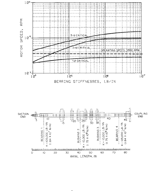
tilevered shaft mount. The stiffness map of the rotor looks like that shown in Figure 1.
This pump has two design faults, as can be seen from the stiffness map.The first is that
an excessively large coupling is used. This heavy overhung mass at the coupling forces the
first shaft resonance to be very near the pump operating speed. Normally, the shaft in this
type of pump is considered to be “rigid;” that is, operating safely below the first undamped
shaft resonance. In this case, the pump is affected by two negatively additive errors. The
BSF a
Pd
2Bd
rpsbc1 a
Bd
Pd
b
2
cos
2
0d
BPF
O
a
Nb
2
rpsba1
Bd
Pd
cos 0
b
BPF
1
a
Nb
2
rpsba1
Bd
Pd
cos 0b
FTF
rps
2
a1
Bd
Pd
cos 0
b
rps
rpm
60
2.3.3 CENTRIFUGAL PUMP MECHANICAL PERFORMANCE 2.407
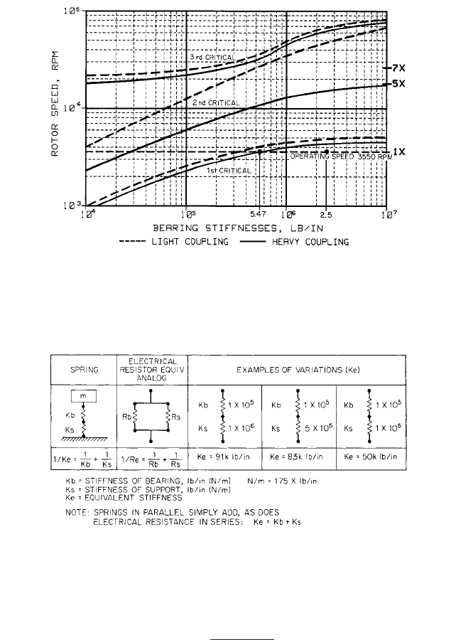
FIGURE 1 Undamped critical speed map of single-stage overhung pump, comparing normal and heavy coupling
weights (lb/in 175 = N/m)
TABLE 1 Logic of spring equivalent stiffness K
e
heavy mass coupling effect is compounded by a weak baseplate that is not properly
grouted, leaving a void under the pump supports. In rotor (shaft) supports, two spring sup-
ports in series reciprocally add, similar to electric resistors in parallel (Table 1).
The effective stiffness is
If the bearing stiffness K
b
, is 2.5 10
6
lb/in (4.4 10
6
N/m) and the support stiffness K
s
,
is low; that is, 7.0 10
5
lb/in (1.2 10
8
N/m), the effective stiffness is 5.47 10
5
lb/in (9.57
10
7
N/m), which moves the first mode resonance from 4300 cpm to 3550 cpm, which is
the running speed of the pump.
The mode shapes of the rotor are shown in Figures 3 and 4.An animated display is used
to better show the rotor gyrations in synchronous whirl. The first modes are shown with a
K
e
1
1>K
b
1>K
s
2.408 CHAPTER TWO
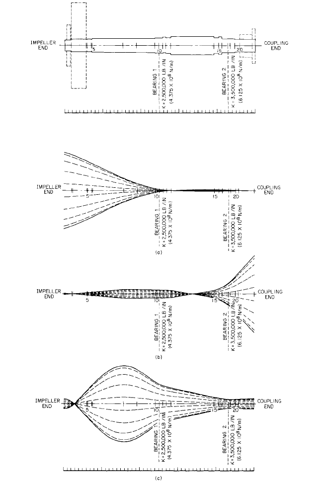
FIGURE 2 Rotor cross section of single-stage overhung pump with normal coupling weight. Rotor weight =
110.4 lb (50kg); rotor length = 30.3 in (77.0 cm); number of stations = 22; number of bearings = 2
FIGURE 3 First, second, and third resonate animated mode shapes of single-stage overhung pump with light
coupling of 15 lb (6.8 kg) and rigid foundation. Rotor weight = 110.4 lb (50 kg); rotor length = 30.3 in (77.0 cm);
number of stations = 22; number of bearings = 2. (a) Mode 1: frequency = 4717 cpm; (b) mode 2: frequency = 53,482
cpm; (c) mode 3: frequency = 67,522 cpm
2.3.3 CENTRIFUGAL PUMP MECHANICAL PERFORMANCE 2.409
lighter, normal, and correct coupling (15 lb; 6.8 kg). Figure 2 shows the mathematical
model of this pump with the impeller at station 2, the radial bearing at station 11 at 2.5
10
6
lb/in (4.4 10
8
N/m) stiffness, the outboard thrust/radial bearing at station 18 at 3.5
10
6
lb/in (6.1 10
8
N/m) and the coupling at station 21.
Figure 3a, obtained from a finite element computer analysis of the mathematical model
in Figure 1, shows the first mode with a rotor weight of 110.4 lb (50 kg), a rotor length of
30.3 in (77.0 cm), and a first mode undamped resonance (critical) of 4717 cpm. This is a
pivotal mode, with 100% of the normalized motion at the impeller end. Any motion at the
antifriction bearings is greatly restrained.
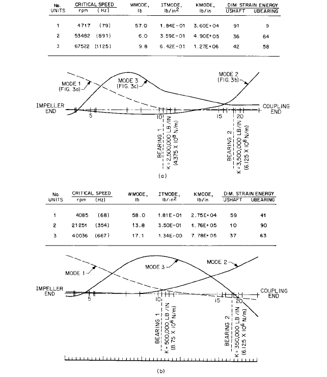
FIGURE 4 Synchronous critical speed summary with first three mode shapes of a single-stage overhung pump
with light coupling of 15 lb (6.8 kg) and rigid or flexible foundation. Rotor weight = 110.4 lb (50 kg); rotor length =
30.3 in (77.0 cm); number of stations = 22; number of bearings = 2. (a) Rigid support, modes 1, 2, and 3 respectively:
4717, 58,482, and 67,522 rpm; (b) flexible support, modes 1, 2, and 3 respectively: 4085, 21,251, and 40,036 rpm. (lb
0.454 = kg; lb/in 175 = N/m)
2.410 CHAPTER TWO
Figure 3b shows the second resonance mode, at 53,482 cpm, which is not to be encoun-
tered. The coupling motion is now the greatest motion.
Figure 3c shows the third mode, at 67,522 cpm.
Figure 4a shows an overlay of all three modes with a summary of the criticals, the
modal mass, and the relative strain energy (91) in the shaft at station 10 (impeller side of
radial bearing). A lesser strain energy is at the radial bearing (station 11).
Figure 4b summarizes what happens to critical speed modes if either a more flexible
bearing or a soft structure is provided intentionally or unintentionally. Also note that the
criticals are lowered significantly and the strain energy is transferred more from the shaft
into the bearings; that is, strain values under the U-shaft column are less than under
U-bearing column. The first critical is 4085 cpm at a pump speed of 3550 rpm (15%). A
15% margin of separation may be close enough to excite (cause a rise in vibration) the rotor
if the resonance response envelope is too wide. However, this is unlikely on antifriction
bearings (spiky/narrow response), but possible on sleeve bearings (low/broad response).
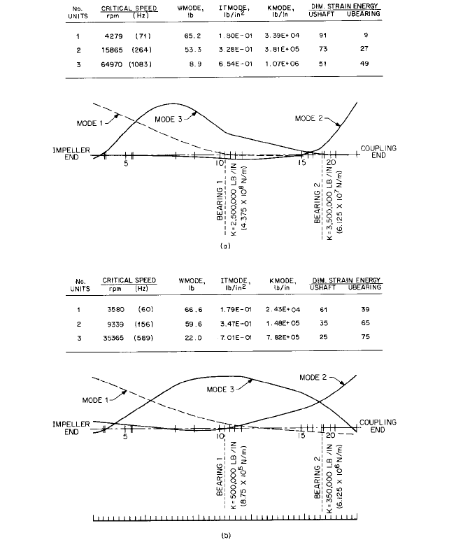
Figure 5a is a summary which shows the response of a rigid support and an excessively
heavy (62 lb 28 kg) coupling, which is as heavy as the impeller. Note that the first mode
is again only slightly above the operating speed; that is, 4279 cpm compared with 3550
(21%).The bearing stiffness is assumed to be the controlling stiffness. Many assume that
the structure or base stiffness is one order above the bearing stiffness (K
s
l0K
b
). This
assumption that the bearing stiffness is the controlling stiffness variable is often a very
poor assumption. The larger the pump size, the more this is true. That is why an 8 6
13 pump was used as an example.
Further, the second mode, at 15,865 cpm, is in an area where the blade passing fre-
quency (5 3550 17,750 cpm) can easily excite this mode, given little variation in sup-
port stiffness. Figure 5b is a summary sheet that best illustrates the problem:
• The baseplate was improperly installed and grouted.
• The elastomeric coupling designed for low-duty, low-speed, and torsional damping was
too heavy; that is, too much overhung weight.
Note that the first critical is in sympathy with the pump operating speed, which
becomes intolerable with the operating time limited to one to two days, due to bearing
failures.
The stiffness on antifriction bearings was determined from a program written by M. E.
Leader of Monsanto, using values projected by an article written by F. F. Garguilo, DuPont.
2
The correction consisted of converting the 62-lb (28-kg) coupling to a 15-lb (6.8-kg) series
dry flex disk-type coupling and stiffening the support by flushing the baseplate cavity with
a degreasing fluid and pressure injection of epoxy to fill the baseplate voids.
It should be remembered that the blade passing frequencies will normally be the
strongest exciting force. On this pump, the frequency is five times running speed (five
vanes times each cutwater). Because there are two cutwaters, there can also be a fre-
quency at 10 times running speed. The 5 frequency is shown on Figure 1. Also, this 5
frequency excitation could excite the second mode because the second mode critical could
fall anywhere between the solid and dashed lines, depending on baseplate stiffness.
The instruments used in diagnosing this problem were force-effective seismic sensors
(velocity or piezoelectric accelerometers). They are preferred for pumps, particularly those
with antifriction bearings.
MULTISTAGE PUMP EXAMPLE _________________________________________
To show the mechanical rotor variations, a six-stage boiler-feed pump with a design capac-
ity of 1250 gpm (284 m
3
/h), 2200 ft (670 m) total head, and driven by a 1000-hp (746-kW),
two-pole motor has been selected. This pump utilizes interstage bushings as support bear-
ings to the rotor. The contribution of these bushings as bearings will probably be less than
might be assumed.
2.3.3 CENTRIFUGAL PUMP MECHANICAL PERFORMANCE 2.411
FIGURE 5 Synchronous critical speed summary with first three mode shapes of a single-stage overhung pump
with heavy coupling of 62 lb (28 kg) and rigid foundation. Rotor weight = 157.4 lb (71.4 kg); rotor length = 30.3 in
(77.0 cm); number of stations = 22; number of bearings = 2. (a) Rigid support, modes 1, 2, and 3 respectively: 4279,
15,865, and 64,970 cpm; (b) flexible support, modes 1, 2, and 3 respectively; 3580, 9339, and 35,565 cpm. (lb 0.454
= kg; lb/in 175 = N/m)
Pressure or seal leakage control bushings contribute rotor support if they are long.The
hot feedwater has very low viscosity and little damping. The bearing stiffness will be rel-
ative to the eccentricity ratio of the shaft in the bushings. An eccentricity ratio of unity
(maximum) implies that the shaft is rubbing directly on its bushing.
The impeller weight is increased by the water trapped in each impeller. Many pump
manufacturers improperly list pump undamped critical speeds from dry pump data or cal-
culations. The bushings, labyrinths, and wear rings all contribute to the actual critical
speed. Also, bearing housing resonances are more common than expected.
2.412 CHAPTER TWO
FIGURE 6 Undamped critical speed map of multistage boiler-feed pump with plain journal bearings (lb/in
175 = N/m)
FIGURE 7 Rotor cross-section of multistage high-pressure boiler-feed pump with plain journal bearings. Rotor
weight = 377.7 lb (171.3 kg), rotor length = 84.6 in (215 cm); number of stations = 47, number of bearings or
bushings = 4 (in 2.54 = cm)
Figures 6 to 9 illustrate it in the same fashion as the previous example the design audit
of a steam-turbine-driven, 4 8 10 , six-stage, boiler-feed pump using hydrodynamic
radial and thrust bearings. No problems were experienced with this pump.
A more complete listing of data from analysis is shown with an added breakdown of the
rotor model and the output of the first, second, and third resonant modes. The first criti-
cal (rotor resonance) is now a cylindrical mode and not a conical mode, as previously seen
for the overhung impeller of the single-stage process pump.
ALIGNMENT OF PUMPS AND DRIVERS__________________________________
Outside of serious unbalance of pump components, there is no single contributor of poor
mechanical performance more significant than poor alignment. Incorrect alignment
between a pump and its driver can cause
• Extreme heat in couplings
• Extreme wear in gear couplings and fatigue in dry element couplings
1
2
2.3.3 CENTRIFUGAL PUMP MECHANICAL PERFORMANCE 2.413
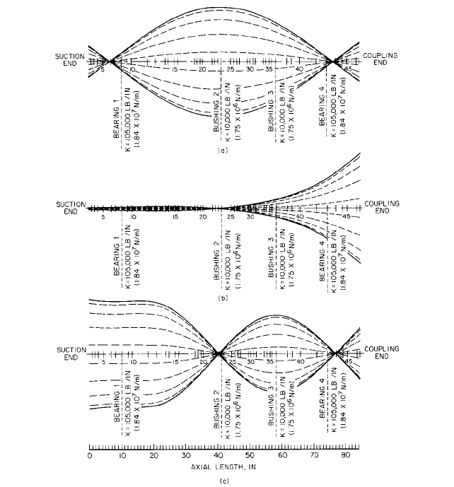
FIGURE 8 First, second, and third resonate animated mode shapes of multistage high-pressure boiler-feed pump
with plain journal bearings. Rotor weight = 377.7 lb (171.3 kg); rotor length = 84.6 in (215 cm); number of stations =
47; number of bearings or bushings = 4. (a) Mode 1: frequency = 2614 cpm; (b) mode 2: frequency = 5223 cpm; (c)
modes: frequency = 8134 rpm. (in 2.54 = cm)
• Cracked shafts and totally failed shafts, with failure due to reverse bending fatigue
transverse to the shaft axis initiating at the change of section between the large end of
the coupling hub taper and the shaft
• Preload on bearings (evident by an elliptical and flattened orbit resembling a deflated
beach ball); pure asymmetry of vertical and horizontal vibration can be misleading
because the bearing spring constants could vary greatly in the k
yy
(vertical) and the k
xx
(horizontal) axis.
• Bearing failures plus thrust transmission through the coupling, which can be totally
locked (axial vibration checks across the coupling; that is, at each adjacent machine, will
generally confirm this condition)
Significant changes in the cold nonrunning alignment of a pump and driver can take
place if the temperature rise in each machine is different and if the piping imposes forces
on the pump.

2.414 CHAPTER TWO
FIGURE 9 First three critical speed mode shapes of multistage high-speed boiler-feed pump superimposed (in
2.54 = cm)
Therefore, alignment under actual operating conditions must be predicted or, if
unknown, confirmed by instrumentation. In either case, an allowance must be made in
the initial cold alignment to compensate for changes in alignment from cold idle to hot
running.
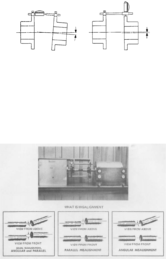
There are several techniques for measuring cold and hot alignment. The cold align-
ment is generally measured by either face and rim (Figure 10) or reverse dial indicator
(Figure 11) methods.
The face and rim method has a sensitivity advantage when the diameter of a coupling
exceeds the indicator span of reverse indicator bracket tooling. This is rare, as the pump will
generally have a spacer coupling and the reach of the reverse indicators can be increased
by clamping onto the shaft behind each coupling half. The face and rim method would also
have an advantage if either the driver or the gear could not be rotated, as it seems unlikely
that the pump could not be rotated. In order to compensate for the measuring surface’s not
being circular or smooth, both shafts should be rotated together when using this method.
Disadvantages of Face and Rim Method
1. Diameters of the rim must be true (circular) and smooth and the face reading surface
must be flat and smooth, unless both shafts are rotated together.
2. The driver and pump cannot float axially while a reading is being taken or an error
will be introduced into the face (angular) reading. (A fixed axial stop will assist in
reducing errors.)
Reverse Dial Procedure for Measuring Alignment (Hot or Cold) Several procedures
have been suggested by various people to estimate or actually measure alignment while
a pump is running at operating temperature. Some techniques are
1. Shutdown after temperatures have stabilized for “hot check” by dial indicators
2. Optical measurements cold to hot (A. J. Campbell, Compressor Engineering Corp.,
Houston)
3. Dodd bars (DynAlign) technique (B. Dodd, Chevron
3
)
2.3.3 CENTRIFUGAL PUMP MECHANICAL PERFORMANCE 2.415
FIGURE 10 Face and rim dial indicator method (Courtesy Rexnord)
Check for Angular Misalignment Dial indicator mea-
sures maximum longitudinal variation in hub spacing
through 360° rotation.
1. Attach dial indicator to hub, as with a hose clamp;
rotate 360° to locate point of minimum reading on
dial; and then rotate body or face of indicator so the
zero reading lines up with pointer.
2. Rotate both half couplings together 360°. Watch indi-
cator for misalignment reading.
3. Driver and driven units will be lined up when dial
indicator reading comes within maximum allowable
variation for that coupling style. Refer to specific
installation instruction sheet for the coupling being
installed. Note: If both shafts cannot be rotated
together, connect dial indicator to the shaft that is
rotated.
Check for Parallel Misalignment Dial indicator mea-
sures displacement of one shaft center line from the
other.
4. Reset pointer to zero and repeat operations 1 and 2
when either driven unit or driver is moved during
aligning trials.
5. Check for parallel misalignment as shown. Move or
shim units so parallel misalignment is brought within
the maximum allowable variations for the coupling
style.
6. Rotate couplings several revolutions to make sure no
“end-wise creep” in connected shafts is measured.
7. Tighten all lockouts or capscrews.
8. Recheck and tighten all locknuts or capscrews after
several hours of operation.
FIGURE 11 Model used for training machinist in the use of reverse dial indicator technique for alignment of
machine shafts. Misalignment can be measured as parallel or angular offset.