Pump Handbook by Igor J. Karassik, Joseph P. Messina, Paul Cooper, Charles C. Heald - 3rd edition
Подождите немного. Документ загружается.

9.14.2
NUCLEAR PUMP SEISMIC
QUALIFICATIONS
D. NUTA
W. E. PARRY, JR.
9.301
Nuclear electric generating stations and their components shall be designed to resist the
dynamic forces that could result from an earthquake at the site.This subsection covers the
seismic qualification requirements for pumps classified according to function and impor-
tance based on safe operation and public safety.
SEISMIC CLASSIFICATION OF PUMPS___________________________________
Pumps that must withstand a safe shutdown earthquake (SSE) and remain functional
during and after such an event are designated seismic Category I. Pumps that are not
required to remain functional during SSE are designated nonseismic Category I and may
be classified as follows:
• Nonseismic Category I pumps are located so their failure or structural deformation
might keep a seismic Category I piece of equipment or system from performing its
intended function. The analysis methods and seismic input used on nonseismic
Category I pumps to show that gross failure or excessive deformations will not occur
are identical to those used for seismic Category I equipment.
• Nonseismic Category I pumps are located so their failure or structural deformation can-
not affect any seismic Category I system or component. Seismic-related requirements
for these pumps, if any, are established using a less stringent seismic environment with
the aim of minimizing possible replacement expenses following a credible event.
9.302 CHAPTER NINE
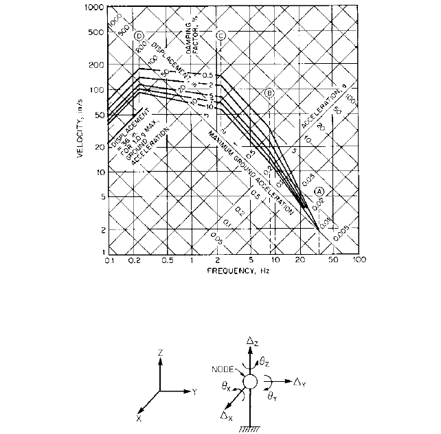
FIGURE 2 Nodal degrees of freedom
FIGURE 1 Horizontal design response spectra scaled to 1g ground acceleration (1 in = 2.54 cm; g = 32.17 ft/s
2
= 9.807 m/s
2
)
DEFINITIONS ________________________________________________________
Critical Damping
This is the minimum damping for which a vibrating system has no
vibratory motion. For analysis purposes, damping is expressed as a percentage of critical
damping. The amplification of input motion, or magnitude of response, is inversely pro-
portional to the damping ratio of the vibrating system. Figure 1 shows responses obtained
for damping ratios which vary from 0.5 to 10% of critical damping.
Damping Damping is the dissipation of energy in a vibrating system. Damping is a
function of many factors, including material characteristics, stress levels, and geometric
configurations and takes place as a result of the transformation of input energy in the
form of seismic motion to heat, sound waves, or other energy forms. For analysis purposes,
damping is assumed to be viscious; that is, the damping force is proportional to velocity
and acts in the opposite direction.
Degrees of Freedom The degrees of freedom are the coordinate(s) necessary to ade-
quately describe the behavior of a structure or component. A node, or nodal point, may
have as many as six degrees of freedom, consisting of three translations and three rota-
tions (such as
x
,
y
,
z
, u
x
,u
y
,u
z
, as shown in Figure 2). This complex representation in
9.14.2 NUCLEAR PUMP SEISMIC QUALIFICATIONS 9.303
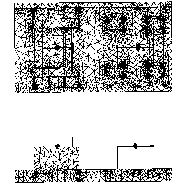
FIGURE 3 Typical FEM mesh of Horizontal Pump/Motor Assembly Pump and motor are modeled as lumped-
mass elements whereas bedplate is modeled with shell elements.
terms of degrees of freedom is used when performing static analysis to obtain forces,
stresses, or displacements.
Finite Element Method The finite element method of analysis involves the idealization
of a structure or component, such as a pump, as an assemblage of elements of finite size.
This mathematical model can be a lumped-mass model, a shell element model, a three-
dimensional solid model, or a combination of all three. Figures 3 and 4 contain typical shell
element models of horizontal and vertical pumps respectively.
Floor Acceleration This is the acceleration at a structural floor or any acceleration
applicable at the equipment mounting location.
Ground Acceleration Ground acceleration is the acceleration of the ground associated
with earthquake motion.
Modal Analysis Modal analysis is a type of dynamic analysis in which the response of
a vibrating system is obtained as a combination of responses of the system’s mode shapes.
(Specific requirements on the combination of modal responses is contained in U.S. Nuclear

9.304 CHAPTER NINE
FIGURE 4 Typical FEM mesh of Vertical Circulating Water Pump. The pump is modeled with shell elements
while the motor is modeled with lumped-mass elements.
Regulatory Commission Guide 1.92.) Modal analysis may be used in conjunction with a
response spectrum or time history analysis.
Natural Frequency The natural frequency is the frequency at which a body vibrates
due to its own physical characteristics and to the elastic restoring forces developed when
it is displaced in a given direction and then released while restrained or supported at spe-
cific points.
Operating Basis Earthquake (BE) An operating basis earthquake is an earthquake
that could reasonably be expected to affect a plant site during the operating life of the
plant. The systems and components necessary for continued operation of a nuclear plant
without undue risk to public health and safety are designed to remain functional when
subjected to the vibratory ground motion produced by an operating basis earthquake.
Required Response Spectrum (RRS) The RRS is the response spectrum for which
the equipment (pump assembly) has to be dynamically qualified.
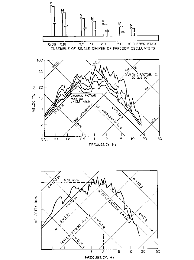
Response Spectrum The response spectrum is the plot of the maximum response
(acceleration, velocity, displacement) of a series of damped single-degree-of-freedom (SDF)
oscillators versus the natural frequencies (or, sometimes, periods) of the oscillators when
subjected to the vibratory motion input (time history) at their supports. Figure 5 repre-
sents a plot of response spectra obtained for 0, 2, 5, and 10% of critical damping with an
earthquake time history as input. The plot is on tripartite log paper, and only a limited
number of SDF oscillators are shown (usually, more than 70 are needed to correctly define
a spectrum).
In order to facilitate the understanding of how to use the Figure 5 plots, the 0% of crit-
ical damping response spectrum is presented in Figure 6. Assuming a SDF oscillator hav-
ing a frequency of 2 cycles/s (Hz), the maximum displacement of the mass point when
subjected to the earthquake record is 7 in (17.8 cm), the maximum velocity is 50 in/s (1.27
m/s), and the maximum acceleration is 2g, where g gravitational acceleration 32.2
ft/s
2
(9.807 m/s
2
). A line is drawn perpendicular to the frequency axis, and from the inter-
section of this line with the spectrum curve, a line parallel to the acceleration lines will
9.14.2 NUCLEAR PUMP SEISMIC QUALIFICATIONS 9.305
FIGURE 6 Response displacement, velocity, and acceleration versus frequency (1 in/s = 0.0254 m/s; 1 in = 2.54
cm; 1g = 32.17 ft/s
2
= 9.807 m/s
2
)
FIGURE 5 Response spectra plots for various dampings (1 in/s = 0.0254 m/s; 1 in = 2.54 cm; 1g = 32.17 ft/s
2
= 9.807 m/s
2
)
provide the acceleration a 2g, a line parallel to the displacement lines will provide the
displacement d 7 in (17.8 cm), and a line perpendicular to the velocity axis will provide
the velocity y 50 in/s (1.27 m/s).
In general, response spectra are presented as plots of acceleration versus frequency.
Given a time history of acceleration, such as the one presented in Figure 7, the response
spectrum is obtained as described previously. The response acceleration at frequencies above

9.306 CHAPTER NINE
FIGURE 7 Development of acceleration response spectrum (1g = 32.17 ft/s
2
= 9.807 m/s
2
)
33 Hz (also called zero period acceleration) is equal to the peak acceleration of the time his-
tory record regardless of the damping ratio used (the value a is specified in Figure 7).
Response Spectrum Analysis The response spectrum analysis is a modal dynamic
analysis that uses response spectra as vibratory input at the pump attachment points.
Safe Shutdown Earthquake (SSE) An SSE is an earthquake that produces the max-
imum vibratory ground motion for which certain structures, systems, and components are
designed to remain functional. These structures, systems, and components are those nec-
essary to assure (1) the integrity of the reactor coolant pressure boundary, (2) the capa-
bility to shut down the reactor and maintain it in a safe shutdown condition, or (3) the
capability to prevent or mitigate the consequences of accidents that could result in poten-
tial offsite exposures to radioactive material. Various safety classes are assigned to struc-
tures, systems, and components as a function of which of these three categories they
belong to.
Single-Degree-Of-Freedom Oscillator (SDF) The SDF is a vibrating system consist-
ing of a single node point where the mass is concentrated and supported by a beam and
spring element. If the single dynamic degree of freedom is along the axis of the beam, the
frequency of the oscillator is
where f frequency, cycles/s or Hz
K EA/L spring stiffness, lb/in (N/mm)
E Young’s modulus of elasticity of support beam, lb/in
2
(Pa)
A cross-sectional area of support beam, in
2
(mm
2
)
L length of support beam in (mm)
M mass lb s
2
/in (N s
2
/mm)
f
1
2p
B
K
M

9.14.2 NUCLEAR PUMP SEISMIC QUALIFICATIONS 9.307
FIGURE 8 Single-degree-of-freedom oscillator
With this idealization, the frequency of the SDF oscillator may be varied by changing
the length of the beam element and maintaining E, A, and M constant (Figure 8). A hori-
zontal degree of freedom would be used in conjunction with beam bending and shearing.
Damping effects are simulated by a dashpot, which can be assigned different damping
ratios.Although there is little effect on the frequency of the SDF oscillator when the dash-
pot is assigned damping ratios below 10 or 15% of critical damping, there is a significant
effect when higher values are used. Thus, if the dashpot is assigned 100% of critical damp-
ing, the oscillator will behave as a rigid body, duplicating, without amplification, the sup-
port input motion.
Test Response Spectrum (TRS) The TRS is a response spectrum that is either theo-
retically constructed or derived using spectrum analysis based on the actual motion of the
shake table (during dynamic testing).
Time History Analysis The time history analysis is an analysis performed in the time
domain using time history vibratory input. A direct integration or modal analysis may be
performed.
Time History of Acceleration The time history of acceleration is a variation of accel-
eration as a function of time during the postulated duration of the seismic event.
Zero Period Acceleration (ZPA) The ZPA is a response acceleration at frequencies
above 33 Hz.
Although these definitions will facilitate the understanding of the seismic considera-
tions discussed herein, the reader is encouraged to review the works listed at the end of
this subsection for a more complete list of terms and definitions used in the process of
dynamic qualifications.
SEISMIC QUALIFICATION REQUIREMENTS_______________________________
The seismic qualification of seismic Category I pumps is performed to demonstrate the
ability of the equipment to perform its intended function during and after the time it is
subjected to an SSE, which could occur before or after several OBEs.The value of the SSE
or OBE response spectra shall be supplied by the equipment buyer (nuclear facility). The
simultaneous effects of the seismic accelerations in the two orthogonal horizontal direc-
tions and the vertical direction have to be considered.
The seismic qualification can be achieved by
• Analytical methods (static or dynamic analysis)
• Testing the equipment under simulated seismic conditions
• Using a combination of tests and analysis
9.308 CHAPTER NINE
The information that is provided in the IEEE 344 standard on these qualification
methods is applicable to pump assemblies. The information presented hereafter either
emphasizes some of the IEEE 344 requirements or is pertinent to pumps and pump
assemblies in particular.
Qualification by Analysis The initial step in qualifying a pump assembly by analyti-
cal methods is to determine the rigidity of the assembly. If the assembly has its lowest
natural frequencies greater than the ZPA frequency, typically 33 Hz, the assembly is con-
sidered rigid. On the other hand, if one of its natural frequencies falls below the ZPA, the
assembly is considered flexible. Therefore, prior to conducting the qualification analysis,
the natural frequency of the pump assembly must be determined by either a modal analy-
sis or an equipment “bump” test. The FEM models as shown in Figures 3 and 4 can be
used for the modal analysis.
After the rigidity of the pump assembly has been determined, the type of qualification
analysis can be selected. The allowable types of analysis are
• Static analysis If it can be shown that the equipment is rigid, a static seismic
analysis may be performed to determine the stresses and deformations due to the
dynamic seismic loads.The dynamic forces shall be determined by multiplying the mass
of the assembly times the maximum floor acceleration (ZPA from the response spectra).
These forces are then applied through the center of gravity of the assembly. The
resulting stresses from each acceleration force are combined by taking the square root
of the sum of the squares (SRSS) to yield the total dynamic stress. The dynamic
deflections shall be calculated in the same manner.
• Simplified dynamic analysis If it has been determined that the equipment is flexi-
ble and the customer specification permits, a simplified dynamic analysis may be com-
pleted applying the same method as the static analysis but using different values for the
dynamic floor accelerations.The applicable floor acceleration shall be obtained by multi-
plying the acceleration values corresponding to the fundamental natural frequency from
the appropriate response spectra curve by 1.5. If the fundamental natural frequency is
not known, the maximum peak value of the response spectras shall be multiplied by 1.5.
The 1.5 factor will conservatively account for possible participation of higher modes.
• Detailed dynamic analysis When justification for a static analysis cannot be
provided, a detailed dynamic analysis is required, unless a conservative factor is used
to account for the participation of higher modes (simplified dynamic analysis). A
mathematical model of the equipment is required to determine the dynamic behavior
of the equipment. This mathematical model may be a lumped-mass model, a shell model
(see Figure 4), a solid element model, or a combination such as shown in Figure 3. The
model should include, when applicable, the hydrodynamic mass that represents the
contained water or the effects of submergence on vertical pumps. This model is then
analyzed using either response spectra modal analysis or time-history (modal or step-
by-step) analysis. The various modal contributions shall be combined by taking the
SRSS of the individual modal stress and deformations.
These dynamic analyses are performed with computer programs in the public domain.
Such programs include ANSYS, MSC/NASTRAN, ALGOR, and COSMOS/M, which incor-
porate acceptable methods of combining modal responses, or with a multitude of other
finite element programs that are either commercially available or developed specifically
for the analysis. Further information regarding specific items related to dynamic analysis,
such as damping ratios, combination of modal responses, and modeling techniques may be
obtained from the works listed at the end of this subsection. Although recent advance-
ments in computer technology and software have made this type of analysis more readily
available, when performing detailed dynamic analyses, a thorough understanding,
obtained from experience, is imperative.
After these seismic stresses and deformations have been obtained, they must be com-
bined with the other equipment stresses and deformations, resulting from all of the applic-
able loads, in order to determine the acceptability of the equipment.
9.14.2 NUCLEAR PUMP SEISMIC QUALIFICATIONS 9.309
Qualification by Testing The equipment is tested by using the applicable seismic infor-
mation (floor response spectrum or time history). The input test motion should have a TRS
that closely envelopes the RRS, and the test should simulate the occurrence of five OBEs
followed by one SSE.
Both the pump and the motor are tested under conditions that simulate as closely as
possible actual operating conditions and operability. The operability of the pump, which is
tested without the piping system attached and in the absence of any fluid, is established
by the absence of undue large deflections during testing (which implies low stress levels)
and by performance at the end of the test.
The input motion used must have a maximum acceleration equal to or greater than the
ZPA and cannot include frequencies above the frequency associated with the ZPA. The
input motion is applied to one vertical and one horizontal axis (resultant) simultaneously
unless it can be proved that coupling effects are negligible. In general, multiaxis testing
using independent random inputs is required.
Unless it has complete symmetry about its vertical axis, the equipment is rotated 90°
and retested.
The mounting and support details used during testing should simulate the service
mounting as closely as possible and should be designed so the mounting will not cause
dynamic coupling to the test assembly or alter the input motion.
Combination of Test and Analysis If the motor assembly is tested separately and the
pump is qualified by analysis, RRS at the motor assembly attachment points are devel-
oped from the pump assembly seismic analysis and used in the motor assembly testing.
If both the pump assembly and the motor have to be tested but it is not feasible to test
them together, dummy weights are used to replace the assembly part not included in the
test and RRS at the location are established and used in testing the missing part.
DESIGN AND FUNCTIONAL REQUIREMENTS _____________________________
The preceding sections provided the procedures for determining the seismic response of
pumping equipment. However, in order to determine the acceptability of these results,
they have to be combined with the pump’s normal operational loads and compared to pre-
determined stress limitations. In accordance with the ASME code, the customer’s design
specification shall advise the applicable load combinations and allowable stress values.
Typically, the pump load combinations can be divided into four levels or service limits.
Table 1 lists these service limits in ascending order dependent upon the magnitude of com-
ponent deformation resulting from operation at the prescribed condition. In addition,
Table 2 lists the ASME code allowable stress limits for each of these conditions. If no allow-
able stress limits are specified in the customer’s design specification, no allowable stress
increases should be used for the increasing load combinations, including those for OBE
and SSE operation.
In addition to the specific requirements for stress levels or functionality of pressure
containing components, the following items should be addressed as part of any seismic
qualification of pump-motor assemblies:
• Secondary stress loading caused by differential movement of connected components
should be determined.
• Displacements and deflections should be measured during testing or calculated, if qual-
ified by analysis, in order to assure they are not excessive.
• Loads to be used in the design of the pump-motor assembly foundation and anchorage
should be established.
• Seismic loads must be added to other normal shaft loads in order to verify stress levels,
bearing loads, running clearances and possibly coupling misalignment.
• For electric motors, deflections or component dislocations should be closely monitored in
order to assure that

9.310 CHAPTER NINE
TABLE 1 Typical load combinations and stress limits
Design/
Plant Condition Normal Upset Emergency Faulted
Concurrent PD SL PD SL SOT PD SL PD SL
Loads SOT OBE SOT SSE
Design/Stress Level A Level B Level C Level D
Limits
Where:
PD Design pressure and temperature
SL Sustained loads including dead weight and applied nozzle loads
SOT System operating transients for upset, emergency, and faulted conditions per cus-
tomer specifications
OBE Operating basis earthquake
SSE Safe shutdown earthquake
Level A Those loadings that the pump may be subjected to in the performance of its specified
function
Level B Those loadings that the pump must withstand without damage requiring repair
Level C Those loadings that may result in large deformations that necessitate the removal of
the pump from service for inspection or repair
Level D Those loadings that result in gross general deformations with some consequent loss
of dimensional stability and damage requiring repair, which may require removal of
the unit from service
TABLE 2 Stress limits
Service limits Stress limits (maximum normal stress)
Design and Level A s
m
1.0S
(s
m
or s
L
) s
b
1.5S
Level B s
m
1.1S
(zs
m
or s
L
) s
b
1.65S
Level C s
m
1.5S
(s
m
or s
L
) s
b
1.8S
Level D s
m
2.0S
(s
m
or s
L
) s
b
2.4S
s
m
General membrane stress; equal to average stress across solid section under considera-
tion; excludes discontinuities and concentrations and is produced only by pressure and
other mechanical loads
s
L
Local membrane stress; same as s
m
except that s
L
includes effect of discontinuities
s
b
Bending stress; equal to linearly varying portion of stress across solid section under con-
sideration; excludes discontinuities and concentrations and is produced only by mechan-
ical loads
S Allowable stress, given in Tables I-7.0 and I-8.0 of the ASME code; corresponds to highest
metal temperature of section during condition under consideration
S
OURCE
: ASME Boiler and Pressure Vessel Code, Section III, Nuclear Power Plant Components, Division I, Sub-
section NC, 1992, New York.
• The rotor will not grind into the stator.
• The fan blades will not damage the winding insulation.
• There is no loss of lubricant and no slipped winding or winding temperature detector.