Pump Handbook by Igor J. Karassik, Joseph P. Messina, Paul Cooper, Charles C. Heald - 3rd edition
Подождите немного. Документ загружается.


9.281
TABLE 1 Typical nuclear pump parameters in PWR plants
Length or
Design height,
Number Flow, pressure, Design Driver including Speed
per gpm Head, lb/in
2
temp., hp driver, (nominal),
Pump plant (m
3
/h) ft (m) (MPa) °F (°C) (kW) Shaft in (mm) rpm Notes
Reactor coolant 4 100,000 290 2500 650 7000 Vert. 305 1200
(22,700) (88) (17.2) (343) (5220) (7750)
Component cooling 3 4800 250 200 200 450 Horiz. 110 1800
water (1090) (76) (1.38) (93) (336) (2790)
Residual heat removal 2 3800 350 600 400 500 Vert. 97 1800
(863) (107) (4.14) (204) (373) (2460)
Containment spray 2 2600 450 300 300 400 Horiz. 112 1800
(590) (137) (2.07) (148) (298) (2840)
Spent fuel pit cooling 3 4500 150 150 200 250 Horiz. 87 1800
(1022) (46) (1.03) (93) (186) (2210)
Charging (centrifugal) 2 120 5800 2800 300 600 Horiz. 234 4850 Gear drive
(27) (1768) (19.3) (148) (448) (5940)
Charging (reciprocating) 1 98 5800 2800 250 200 Horiz. 208 205 Reciprocating
(22) (1768) (19.3) (121) (149) (5280)
Safety injection 2 440 2680 1750 300 450 Horiz. 190 3600
(100) (817) (12.07) (148) (336) (4830)
Chilled water 2 400 150 150 200 40 Horiz. 52 3600
(91) (46) (1.03) (93) (30) (1320)
Spent resin sluicing 1 150 250 240 250 30 Horiz. 46 3600
(34) (76) (1.66) (121) (22) (1170)
Reactor coolant drain 2 150 250 240 250 30 Horiz. 46 3600
tank (34) (76) (1.66) (121) (22) (1170)

9.282
TABLE 1 Continued.
Length or
Design height,
Number Flow, pressure, Design Driver including Speed
per gpm Head, lb/in
2
temp., hp driver, (nominal),
Pump plant (m
3
/h) ft (m) (MPa) °F (°C) (kW) Shaft in (mm) rpm Notes
Boric acid transfer 2 100 200 150 200 15 Horiz. 45 3600
(22.7) (61) (1.03) (93) (11) (1140)
Boron recycle 2 100 200 150 200 15 Horiz. 45 3600
evaporator feed (22.7) (61) (1.03) (93) (11) (1140)
Boron injection 2 20 100 240 200 3 Horiz. 18 3600 Canned
recirculation (4.5) (30.5) (1.66) (93) (2.2) (460)
Spent fuel pit skimmer 1 100 50 150 200 3 Horiz. 42 1800
(22.7) (15.2) (1.03) (93) (2.2) (1070)
Refueling water 1 200 200 150 200 30 Horiz. 52 1800
purification (45) (61) (1.03) (93) (22) (1320)
Waste processing 5 100 200 150 200 15 Horiz. 45 3600
system (22.7) (61) (1.03) (93) (11) (1140)
Gas decay tank drain 1 10 90 150 180 3 Horiz. 15 3600
(2.27) (27) (1.03) (82) (2.2) (380)
S. G. blowdown
—
spent 1 110 165 150 100 15 Horiz. 39
resin sluice (25) (50) (1.03) (37) (11) (990) 3600
Source: Westinghouse Electric.
9.14.1 NUCLEAR ELECTRIC GENERATION 9.283
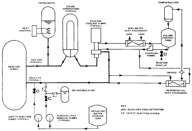
FIGURE 1 Flow diagram for pressurized water reactor coolant system (Westinghouse Electric)
All of the pumps and vital equipment associated with pipe rupture (that is, the emer-
gency core cooling system) is supplied with diesel generator electrical power backup. If
needed, the diesel generators will accept the various pump loads sequentially at intervals
of a few seconds until all needed equipment is on line.
Other pumps serve other systems. Spent fuel pit pumps provide the necessary cooling
of the fuel elements that have been removed from the reactor. Resin beds, which are a part
of the water purification system, are flushed to a storage tank by spent resin sluicing
pumps. An evaporator package, partly for removing boron from the primary water, is sup-
plied by recycle evaporator feed pumps. Chilled water pumps supply the boron thermal
regeneration system. Similarly, other pumps, some not listed in Table 1, support auxiliary
systems.
BWR Plants In boiling water reactor (BWR) plants, active boiling takes place in the
nuclear core and steam is piped to the turbogenerator (Figure 5). Typical reactor water
conditions are 1000 lb/in
2
gauge (6.895 MPa) and 550°F (288°C). In the United States, the
plant is usually arranged with a low-leakage containment vessel completely surrounding
a dry well and a pressure-suppression pool (Figure 6). The containment vessel is a cylin-
drical steel or concrete structure with an ellipsoidal dome and a flat bottom supported by
a reinforced concrete mat. The containment forms a security barrier and prevents the
escape of radioactive products to the atmosphere if an accident should occur.
Table 2 shows the principal pumps used in BWR plants together with significant char-
acteristic data.
To assure a high reactor flow rate and to avoid local areas of core overheating, internal
jet pumps have been used in all but the earliest U.S. BWR plants.These jet pumps are dri-
ven by large-volume, medium-head recirculation pumps. Variable flow rate is achieved
either by flow control valves or by variable-speed motors driven by motor generator sets.
The latest designs employ a flow control valve. The use of jet pumps decreases the size of
the external loop piping and pumps and provides a core reflood capability in the event of
pipe rupture. The main recirculation pumps are not required for emergency cooling. In
9.284 CHAPTER NINE
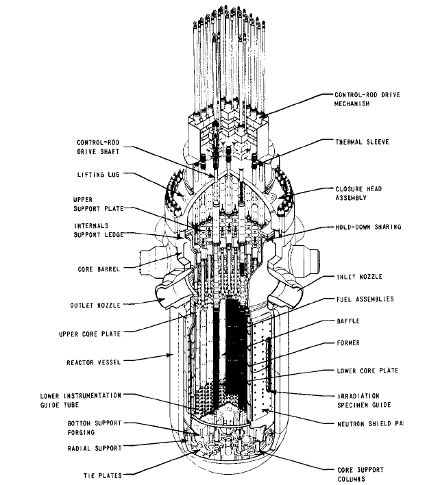
FIGURE 2 PWR reactor vessel (Westinghouse Electric)
normal operation, the recirculation pumps operate in conjunction with the jet pumps,
which are wholly contained in the reactor vessel. The purpose of the jet pumps is to
increase the flow from the recirculation pumps at reduced head for reactor cooling.The jet
pumps have no moving parts. In addition to their normal service, they also play a role in
the natural circulation of the reactor water during emergency cooling.
Several subsystems operate in support of the recirculation system, and each contains
one or more pumps. Reactor water cleanup pumps are used in a filter-demineralizer sys-
tem to remove particulate and dissolved impurities from the reactor coolant. This system
also removes excess water from the reactor. The control rods are operated hydraulically
with water pressure provided by the control rod drive pumps. The pumps are located in an
auxiliary building, and the fluid is piped to the control rod drive units, which are posi-
9.14.1 NUCLEAR ELECTRIC GENERATION 9.285
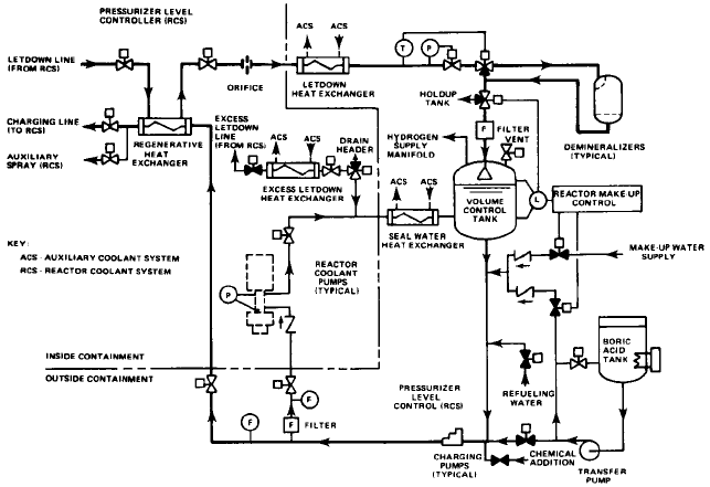
FIGURE 3 Flow diagram for chemical and volume control system (Westinghouse Electric)
tioned directly under the reactor vessel. For those components that require constant cool-
ing, such as the recirculation pump motors and other equipment located in the contain-
ment, auxiliary, fuel, or radwaste buildings, closed cooling water pumps furnish the
necessary flow. These pumps are located in an auxiliary building to permit ready access for
servicing if needed. The system is closed so it can be isolated from an ultimate, usually raw
water, heat sink, such as a river, lake, or ocean.
To cool the fuel stored under water in the fuel building and the water in the upper con-
tainment, separate fuel pool cooling pumps are provided in an independent system.
The emergency core cooling system is in reality an array of subsystems providing the
necessary features, including redundancy, to protect the core in case of a significant
malfunction. The high-pressure core spray system uses a vertical high-pressure core spray
pump, motor-driven but backed by a diesel generator in event of loss of electric power. This
pump, a single unit, provides the initial response when a small pipe breaks or an equiva-
lent malfunction occurs. Should this system be inadequate to maintain reactor water level,
the reactor vessel is automatically depressurized and the low-pressure core spray pumps
supply additional capacity. As an added safeguard, the RHR pumps are used in a
secondary-mode operation to inject cooling water directly into the reactor vessel. If steam
should enter the containment region, the RHR pumps operate in another mode
—
as con-
tainment spray pumps
—
and are manually operated to condense the steam and thus
reduce any potential pressure buildup in the containment. The RHR pumps function when
needed to limit the temperature of the water in the suppression pool. The turbine-driven
reactor core isolation cooling pumps, in a redundant and independent system, inject cool
water into the reactor vessel. The standby liquid control system pumps inject boron solu-
tion into the reactor for alternative shutdown.
9.286 CHAPTER NINE
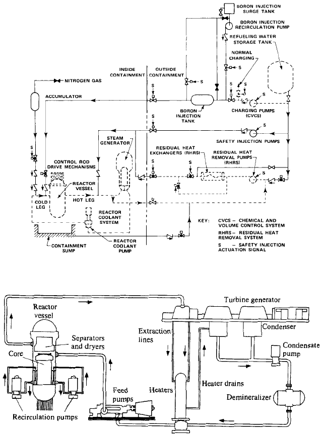
FIGURE 4 Flow diagram for safety injection system (Westinghouse Electric)
FIGURE 5 Boiling water direct cycle reactor system (General Electric)
Additional Equipment In addition to these systems, a number of support systems exist,
most of which require some form of pumping. Without attempting to describe their sys-
tems, there are, for example, pumps for feedwater, condensate, chilled water, booster ser-
vice, condenser service, demineralized water transfer, condensate transfer, dry-well drain,
containment drain, concentrated borated water tank, water leg, precoat, radwaste, and
sample station.
9.14.1 NUCLEAR ELECTRIC GENERATION 9.287
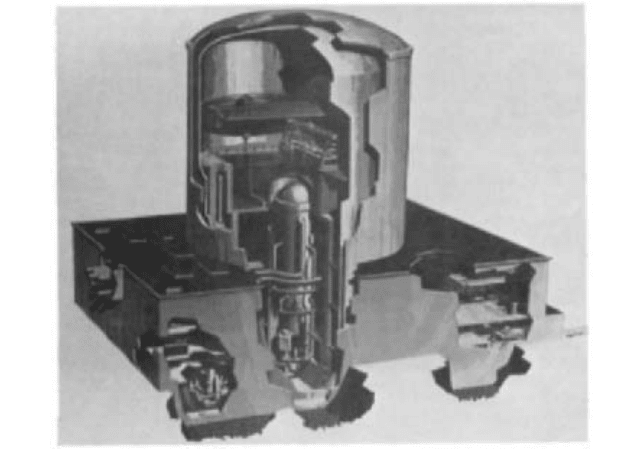
FIGURE 6 BWR containment and reactor vessel, showing one of two external recirculation pumps (General
Electric)
MAIN COOLANT PUMPS ______________________________________________
The term main coolant pumps as used here includes both the recirculation pumps in BWR
plants and the reactor coolant pumps in the primary systems of PWR plants. As shown
typically in Figures 7, 8, 9, and 10, main coolant pumps use a vertical shaft with the
impeller at the bottom and a drive motor coupled to the top end of the shaft.
Bearings Main coolant pumps are usually single-bearing units, although one manu-
facturer provides a second guide-and-thrust oil-lubricated bearing just below the coupling.
Within the pump, hydrodynamic water-lubricated bearings are conventionally used (one
supplier using a hydrostatic type). The hydrodynamic bearing generally consists of a
hardened sleeve journal shrunk on the shaft and a carbon-lined bearing with some type
of self-aligning feature. Bearing diametral clearances are approximately 1.5 mils per inch
of bearing diameter (0.0015 mm per millimeter). This rather large clearance is desirable
because of thermal transient conditions.Where carbon bearings are used, a cooling mech-
anism must be provided because the carbon is not suited to long exposure in a hot envi-
ronment. Many methods are available to accomplish this.
With bearings adequately sized and operating in clean water, virtually trouble-free
performance can be expected even with relatively frequent starts and stops.
The hydrostatic, or pressurized, bearing is used where it is not convenient or desirable
to provide bearing cooling, for the hydrostatic bearing can be designed to operate in reac-
tor temperature water. Usually it will be larger than its hydrodynamic equivalent and
somewhat more sensitive to starting because of the metal-to-metal rubbing that occurs
until rotative speed has built up a small pressure to provide a water film clearance. At nor-
mal operating speed, however, a hydrostatic bearing will have a significantly larger lubri-
cating film than a hydrodynamic bearing and can tolerate larger particulate matter
without wear.
An exception to the previous discussion occurs in both German and Swedish BWR
designs, where the recirculation pumps are inverted and inserted directly into the bottom

9.288
TABLE 2 Typical nuclear pump parameters in BWR plants
Length or
Design height,
Number Flow, pressure, Design Driver including Speed
per gpm Head, lb/in
2
temp., hp driver, (nominal),
Pump plant (m
3
/h)
a
ft (m) (MPa) °F (°C) (kW)
a
Shaft in (mm) rpm Notes
Recirculation coolant 2 44000 760 1675 575 8000 Vert. 240 1800
(9993) (231) (11.55) (302) (5970) (6096)
RHR service water 4 7300 115 150 150 300 Vert. 200 900
(1658) (35) (1.03) (65) (224) (5080)
RHR 3 8520 275 450 212 900 Vert. 350 1800
(1935) (84) (3.10) (100) (670) (8890)
High-pressure core spray 1 1465 2600 1600 212 3000 Vert. 500 1800
(333) (792) (11.03) (100) (2240) (12700)
Low-pressure core spray 1 6000 280 550 212 1750 Vert. 400 1800
(1363) (85) (3.79) (100) (1310) (10160)
Closed cooling water 2 2040 110 150 212 60 Horiz. 100 1800
(463) (34) (1.03) (100) (45) (2540)
Reactor core isolation 1 700 2600 1500 212 800 Horiz. 123 4000 Turbine-
cooling (159) (792) (10.34) (100) (597) (3124) driven
variable-
speed
Fuel pool cooling 2 600 300 150 150 75 Horiz. 95 1800
and cleanup (136) (91) (1.03) (65) (56) (2413)
Reactor water cleanup 2 150 500 1400 560 50 Horiz. 78 3600
(34) (152) (9.65) (293) (37) (1981)

9.289
TABLE 2 Continued.
Length or
Design height,
Number Flow, pressure, Design Driver including Speed
per gpm Head, lb/in
2
temp., hp driver, (nominal),
Pump plant (m
3
/h)
a
ft (m) (MPa) °F (°C) (kW)
a
Shaft in (mm) rpm Notes
Control rod drive hydr. 2 95 3500 1750 150 300 Horiz. 168 1800
system (22) (1067) (12.07) (65) (224) (4267)
Standby liquid control 2 40 2800 1400 150 40 Horiz. 60 1800 Reciprocating
(9) (853) (9.65) (65) (30) (1524) pumps
Jet 20 10000 80 N.A. 575 N.A. Vert. 250 N.A.
(2271) (24) (302) (6350)
Waste evaporator 2 9000 50 50 274 150 Horiz. 120 720
(2044) (15) (0.35) (134) (112) (3048)
Resin tank precoat 1 255 85 150 150 10 Horiz. 65 1800
(58) (26) (1.03) (65) (7.5) (1651)
a
Vary depending on reactor power rating.
Source: General Electric.
9.290 CHAPTER NINE
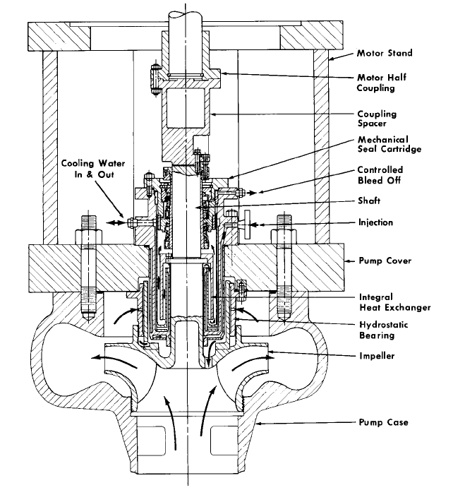
FIGURE 7 Main coolant pump (Flowserve Corporation)
periphery of the reactor vessel and use wet winding motors. There are no jet pumps. Flow
is varied by changing motor speed with solid-state power supplies, one for each recircula-
tion pump.
Seals Pump seals are invariably of the pressure-balanced type because of the high
pressures involved. Several suppliers use pressure breakdown techniques to distribute
the pressure either equally or in some desired proportion between two or more seals in
series (Figure 11). The technique is analogous to that of a potentiometer, where particu-
lar voltages may be obtained by selecting the proper point along an electrical resistance.
Also, as with a potentiometer, the flow through the primary resistance path must exceed
the tapoff flow in order to maintain the system stability. For pressures in PWR systems,
three series seals are frequently used (with each seal taking one-third of the overall pres-
sure), and with lower-pressure BWRs, two series seals are usually sufficient. A margin
of safety is built into the systems such that pump operation can be continued even if one
of the series seals fails.