Pump Handbook by Igor J. Karassik, Joseph P. Messina, Paul Cooper, Charles C. Heald - 3rd edition
Подождите немного. Документ загружается.

9.270 CHAPTER NINE
GOVERNOR TIME AND SURGE TANKS___________________________________
In pumped storage plants, the time specified for the governor servomotors to move the
wicket gates through a complete stroke is generally not less than 30 s. The reasons for this
are that (1) about 30 s is the minimum practicable time for penstock valve operation if the
valve operating machinery is not to be made unduly complicated by the incorporation of
dashpots and accessories and (2) one of the primary purposes of massive EHV connection
is to carry loads from emergency outages for 30 to 60 s or more until the local pumped stor-
age units take over. In the lengths of waterways that are permissible economically, pen-
stock and tunnel velocities may usually be accelerated to full load in a much shorter time
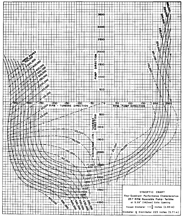
FIGURE 8B Synoptic chart for a 5.59-in (142-mm) opening (1 hp = 0.746 kW; 1 ft = 0.3048 m 1 ft
3
/s;
= 0.0283 m
3
/s) (Voith Siemens Hydro)
9.13 PUMPED STORAGE 9.271
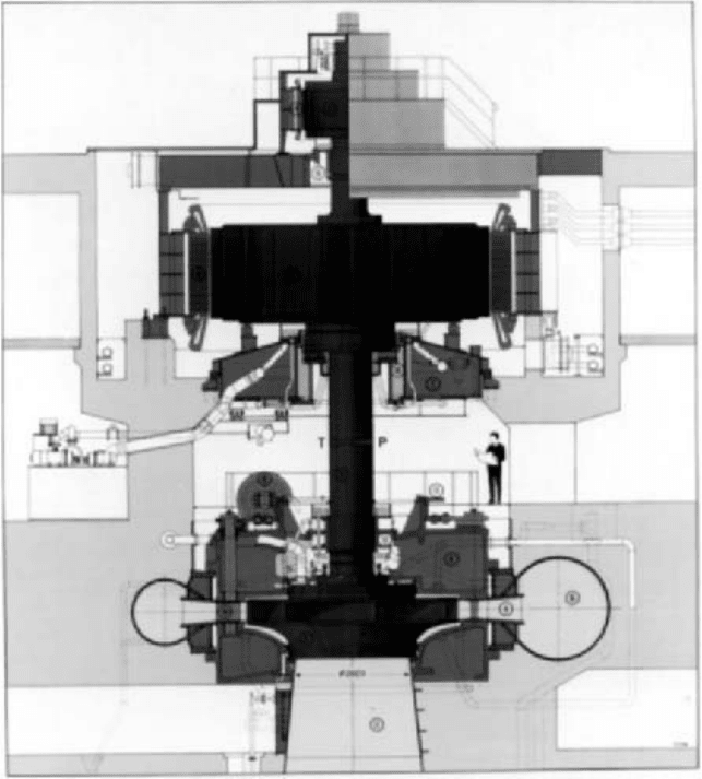
FIGURE 9 Pump-turbine with motor generator. Starting motor is located on top, above the motor-generator. The
pump-turbine runner—surrounded by adjustable vanes, stay vanes, and spiral case—is located above the conical
draft tube that has a minimum throat diameter at the runner eye of 2823 mm (111.1 in). In the turbine mode, flow
is downward and out of the draft tube, and power generated is 210 MW at a head of 250 m (820 ft). In the pumping
mode, the flow direction is reversed, and the motor input power is 198.1 MW at a head of 260 m (853 ft). Speed is
272.7 rpm in both modes (Voith Siemens Hydro)
without excessive positive or negative waterhammer, so surge tanks are not necessary.
However, in the exceptional case of a long tailrace tunnel flowing as a closed conduit,
under the relatively low head of tailwater, even a 30-s closure could be sufficient to pro-
duce negative waterhammer great enough to cause separation of the water column and
damage to the unit. For such cases, a surge tank
1
at the downstream face of the power sta-
tion is required. In a dual-purpose project for municipal water supply and by-product
power, the length of the tunnel is dictated by water supply economics and may be as great
as 40 to 50 miles (64 to 80.5 km). In such cases, a surge tank on the upstream side of the
power station may be indicated.
9.272 CHAPTER NINE
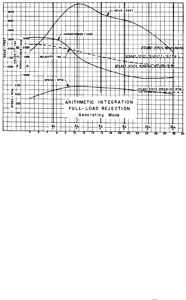
FIGURE 10 Arithmetic integration, full load rejection (1 hp = 0.746 kW; 1 ft = 0.3048 m; 1 ft/s = 0.3048 m/s;
1 ft
3
/s = 0.0283 m
3
/s) versus time in seconds.
ECONOMIC DESIGN __________________________________________________
A proposed pumped storage project for peaking service must be able to show a liberal mar-
gin of economic superiority over competing thermal types. This requires that the under-
taking be designed in accordance with the so-called lean project concept, in which all
elements are closely tailored to the specific purpose of pumped storage and many features
considered standard in the conventional hydroelectric plant are found superfluous.
Selection of the proper site is of paramount importance. The rock should be strong and
tight so no more than local grouting is needed to inhibit leakage and no drainage system for
the concrete lining of the tunnels is required.The upper storage reservoir should preferably
be located in a natural basin in elevated highlands to provide the requisite storage capac-
ity by use of low rimdikes. It is a great advantage if the lower reservoir can be located on
tidewater. The head, probably the most important natural feature, should be high, in the
range from 500 to 1500 ft (152 to 457 m). High head means smaller water quantities and
consequently smaller sizes for a given power output. High head also permits higher turbine
speeds, lower torque, and a smaller generator. The intake need be only a bell mouth at the
end of the supply tunnel; consequently, headgates, cranes, and accessories can be elimi-
nated.The individual units should be of large capacity to ensure minimum equipment costs.
Table 3 shows a typical form for the economic comparison of pumped storage and com-
petitive thermal peaking, and Table 4 is a typical form for the project cost estimate with
its overheads.
Table 5 shows the range of machine requirements for a deep upper reservoir in which
the head variation due to daily drawdown is relatively large. Note that the maximum elec-
tric motor load to develop the full hydraulic capability of the pump, occurring at the min-
imum head of 970 ft (296 m), is 297 MVA. However, this loading is of comparatively short
duration and may be sustained at 80°C temperature rise, which corresponds to 115% of
normal rating.The normal rating at 60°C temperature rise would then be , or 258 MVA,
297
1.15

9.273
TABLE 2 Arithmetic integration at full-load rejection (generating mode; wicket gates at 92% opening)
H
o
H
f
Average
Trial V gH Trial Q (8 Check Hp, 8 hp, 8
Interval Time, (V), H, gH, H
f
, total speed, units), V, units units N
2
, Check
s ft/s ft ft ft H, ft rpm ft
3
/s ft/s (000) (000) rpm
2
rpm
2
T,s
0 0 24.5
——
36.8 1173.2 257 28,100 24.7 3200
—
66,000
(3,510)
a
1 5.3 1.9 274 274 28.8 1455.2 342 25,800 22.6 3040 3120 117,000 51,000 5.30
22.6 (3220)
2 10.6 5.3 766 492 16.9 1685.1 390 19,700 17.3 1180 2110 152,000 35,000 5.30
17.3 (2460)
3 15.9 6.0 867 375 7.2 1577.8 378 12,900 11.3 104 538 142,900 9100 5.30
11.3 (1610)
4 21.2 4.7 680 305 2.5 1512.5 368 7520 6.6 784 444 135,500 7400 5.30
6.6 (940)
5 26.5 3.25 470 165 0.6 1374.4 345 3819 3.35 1200 992 119,000 16,500 5.30
3.35 (477)
6 31.8 0.85 123 42 0.4 1167.0 316 2850 2.5 1080 1140 100,000 19,000 5.30
2.50 (256)
L 12,322 ft, A 1140 ft
2
, a 4650 ft/s, H
f
0.0565V
2
, WR
2
1023 10
6
(8 units), 2L/a 5.3 s, H
o
1210 ft, H a V/g (4650 V)/32.2 144.5 V
SI conversions: m/s 0.3048 ft/s; m 0.3048 ft; m
3
/s 0.0283 ft
3
/s; kW 0.746 hp.
a
Values in parentheses are per-unit values.
¢T
4pWR
2
1N
2
2
N
2
1
2
2g av. hp 550 3600
4p
2
1023 10
6
1N
2
2
N
2
1
2
64.4 av. hp 550 3600
3201N
2
2
N
2
1
2
av. hp
2L
a
N
2
2
2 N
2
1
9.274
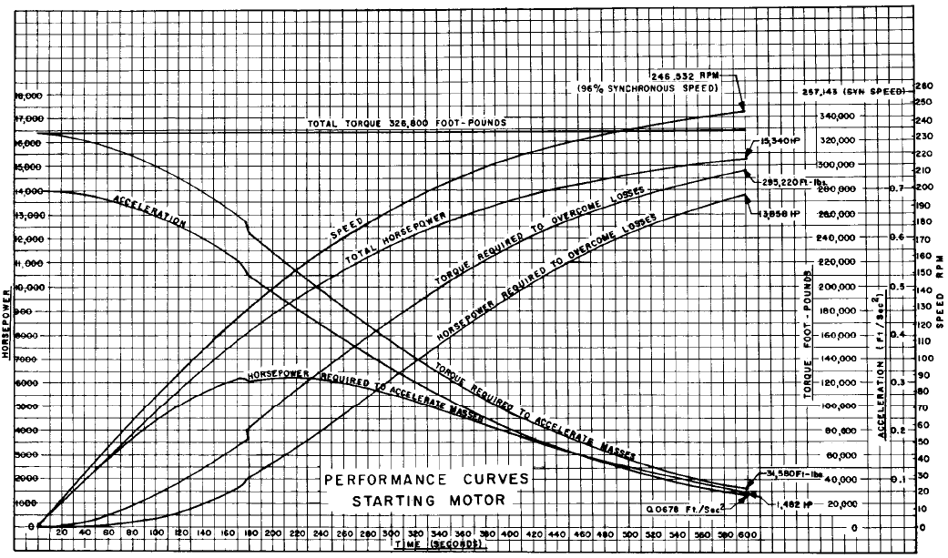
FIGURE 11 Performance curves, starting motor (1 hp 0.746 kW; 1 ft lb 0.138 kg m)
9.13 PUMPED STORAGE 9.275
TABLE 4 Hypothetical pumped storage plant cost estimate-summary
Account no. Item Cost
330 Land and land rights $004,311,000
331 Structures and improvements
1 Powerhouse substructure 20,791,000
2 Service bay substructure 2,023,000
3 Powerhouse superstructure 553,200
4 Cofferdam 600,000
332 Reservoirs, dams, and waterways
2 Reservoir clearing 123,000
4 Dikes and embankments 25,162,000
8 Intakes 1,203,000
12 Power tunnels and waterways 76,526,500
Tailrace 4,940,000
TABLE 3 Economic evaluation of hypothetical pumped storage plant versus
conventional steam reheat plant
Reheat Pumped storage
Installed capacity MW 3,600 3,600
Number of units 4 16
Plant investment (000 omitted)
Generation $450,000 $260,000
Transmission
—
47,100
Total $450,000 $307,100
Total per kilowatt $ 125 $ 85
Annual generation (10
6
kW h)
Peak load 1,300 1,300
Base load 20,000
Total 21,300 1,300
Annual capacity factor, % 67.5 4.1
Annual fixed charge rates, %
Generating plant 13.35 10.90
Transmission plant
—
11.35
Annual costs Total (000) Per kW yr Total (000) Per kW yr
Fixed charges
Generating plant $ 60,076 $16.69 $28,340 $ 7.87
Transmission plant
——
5,347 1.49
Total $ 60,076 $16.69 $33,686 $ 9.36
Fuel 59,044 16.40 5,018
a
1.39
Operation and maintenance 9,900 2.75 3,492 .97
Total $129,020 $35.84 $42,196 $11.72
Credit to reheat unit:
Replacement for base
Load generation 68,480 19.02
Net cost of 3600-MW capacity
and peak-load generation $ 60,540 $16.82 $42,196 $11.72
Differential annual cost in
favor of hypothetical plant $ 9,172 $ 5.10
a
Fuel cost for pumping energy.

9.276 CHAPTER NINE
TABLE 5 Operating range of hypothetical project
Reservoir elevation, ft
1000 1060 1120 1160
Tailwater elevation, ft 0 0 0 0
Gross head, ft 1000 1060 1120 1160
Generating cycle
Friction head loss, ft 30 30 30 30
Net head, ft 970 1030 1090 1130
Best gate turbine output, hp (000)
—
310
Full-gate turbine output, hp (000) 310
—
380 400
Turbine output blocked at, hp (000)
——
350 350
Turbine efficiency, % 85 88.3 87.5 88.5
Turbine discharge, ft
3
/s 3300 3000 3200 3100
Generator output at 98% efficiency, MW 227 227 256 256
Generator MVA (0.90 PF) 252 252 284 284
Pumping cycle
Frictional head loss, ft 20 20 20 20
Net head, ft 1020 1080 1140 1180
Maximum possible discharge, ft
3
/s 2700 2350 2000 1730
Pump power, hp (000) 350 324 298 277
Pump efficiency, % 89.5 89 87 84
Motor power, at 98% efficiency, MW 262 242 223 206
Motor MIVA (0.90 PF) 297 275 252 234
SI conversions: m 0.3048 ft; kW 0.746 hp; m
3
/s 0.0283 ft
3
/s.
TABLE 4 Continued.
Account no. Item Cost
333 Waterwheels, turbines, and generators
2 Fire protection system 86,000
5 Motor generators 31,776,800
8 Spherical valves 7,680,000
9 Turbines and accessories 23,915,520
11 Piezometer system 24,000
13 Spiral case and draft tube unwatering systems 136,000
Air depression system 208,000
Draft tube racks, piers, and guides 2,071,600
334 Accessory electrical equipment 6,496,000
335 Miscellaneous power plant equipment 2,046,000
335 Roads, railroads, and bridges 2,393,600
352 Transmission plant
—
structures and improvements 2,226,500
353 Station equipment 12,119,400
$222,412,120
Contingencies, overhead, and engineering 32,587,880
Total estimated cost of project $260,000,000
which is shown by the tabulation to be adequate to carry pumping and generating load-
ings of more protracted duration. This utilization of overload rating for Class B insulation
affords substantial economies in electric machine cost.
9.13 PUMPED STORAGE 9.277
REFERENCE ________________________________________________________
1. Rich, G. R. Hydraulic Transients, Dover, New York, 1963.
FURTHER READING __________________________________________________
American Society of Mechanical Engineers. Waterhammer in Pumped Storage Projects.
ASME, New York 1965.
Chapin, W. S. “The Niagara Power Project.” Civ. Eng., April 1961, p. 36.
Davis, C. V., and Sorensen, K. E. Handbook of Applied Hydraulics. McGraw-Hill, New
York, 1969.
McCormack, W. J. “Taum Sauk Pumped-Storage Project as a Peaking Plant.” Water Power,
June 1962.
Parmakian, J. Waterhammer Analysis, Dover, New York, 1963.
Rich, G. R., and Fisk,W. B. “The Lean Project Concept in the Economic Design of Pumped-
Storage Hydroelectric Plants.” Paper presented at World Power Conference, 60, September
1964.
Rudulph, E. A. “Taum Sauk Pumped Storage Power Project.” Civ. Eng., January 1963.

APPLICATION _______________________________________________________
The primary difference between the pumps for nuclear service and conventional steam
generation is the stringent requirements for reliability and safety. The continuous func-
tioning of nuclear pumps is critical to the safe operation of the plant. In addition, many of
these units maintain the responsibility of ensuring safe shutdown of the facility during
emergency conditions. Because the release of radioactive fluids could result in potential
personnel and environmental hazards along with associated costly clean-up, nuclear
pumps must be self-contained. The rules and regulatory standards for nuclear pumps are
dedicated to the promotion of public safety through reliable operation. Pump manufac-
turers must be fully knowledgeable of these standards and certified by the American Soci-
ety of Mechanical Engineers (ASME) (or an equivalent authority outside the United
States) before they can offer pumps for the nuclear market.
All nuclear power plants built for public utility service involve the generation of steam.
The method of steam generation differentiates the two major types of plants. The pres-
surized water reactor (PWR) employs two distinct systems, a primary and a secondary
loop. The primary loop circulates pressurized radioactive fluid from the reactor to the
steam generator where it heats the secondary fluid. The secondary loop directs steam from
the steam generator to the turbines and condensed fluid back to the generators. A boiling
water reactor (BWR), on the other hand, only employs one loop. The steam is generated in
the reactor and then circulated through the turbines, condensers, and heaters and back to
the reactor.
It is usual for the plant to contain one major system, or loop, and a number of sup-
porting systems. Because virtually every system requires some form of pumping, it is con-
ventional to designate each pump by the name of the system with which it is associated.
For each of the systems previously discussed, the main and auxiliary systems are
reviewed, including brief descriptions of the pumping requirements.
9.14.1
NUCLEAR ELECTRIC
GENERATION
W. M. WEPFER
W. E. PARRY, JR.
9.279
SECTION 9.14
NUCLEAR
9.280 CHAPTER NINE
PWR Plants Pressurized water reactor (PWR) plants employ two separate main sys-
tems to generate steam. In the primary system, the water is circulated by reactor coolant
pumps through the nuclear reactor and large steam generators. Overpressure is provided
to prevent vapor formation. The secondary side of the steam generator provides nonra-
dioactive steam to the turbogenerator. Typical primary water conditions are 2250 lb/in
2
gauge (15.51 MPa) and 550°F (288°C). Table 1 lists the parameters of the more important
pumps used in PWR plants.
Figure 1 is a simplified flow diagram of a PWR reactor coolant system. Only one pri-
mary loop is shown, but in practice, plants use two, three, or four loops in parallel, each
loop consisting of its own reactor coolant pump, steam generator, and optional stop valves.
A single reactor and pressurizer supply all loops. The pressurizer provides the overpres-
sure referred to by maintaining a body of water at an elevated temperature such that its
vapor pressure satisfies the primary loop pressure requirements.
In the PWR plant, high-pressure water circulates through the reactor core to remove
the heat generated by the nuclear chain reaction. Figure 2 is an illustration of a typical
PWR reactor vessel. The heated water exits from the reactor vessel and passes via the
coolant loop piping to the primary side of the steam generators. Here it gives up its heat
to the feedwater to produce steam for the turbogenerator. The primary-side cycle is com-
pleted when the reactor water is pumped back to the reactor by the reactor coolant pumps.
The secondary-side cycle, isolated from the primary loops, is completed when the feedwa-
ter pumps return water to the secondary side of the steam generator.
Because a reactor, after it has been critical, continues to generate heat even when shut
down, residual heat removal (RHR) pumps are provided to circulate reactor water through
coolers any time the reactor is inoperable and at low pressure, even during refueling.
These pumps serve other functions also, as described next.
The chemical and volume control system (Figure 3) performs a number of functions.
Through charging pumps, which may be centrifugal or positive displacement or may
include some of each type, the primary system can be filled and pressurized when cold.
When the system is hot, the pumps are used to maintain the water level in the pressur-
izer and to replenish any fluid drawn from the primary loops by other systems. Addition-
ally, the pumps supply clean water to the reactor coolant pump seals and are used to
adjust the boric acid concentration in the reactor coolant water, which provides an auxil-
iary means of reactor power regulation. If positive displacement pumps are included in the
chemical and volume control system, they are also used to hydrostatically test the reactor
primary coolant system. Where all the charging pumps are centrifugal, it is customary to
provide a small positive displacement pump exclusively for this hydrostatic testing.
For cooling essential components and for supplying a variety of heat exchangers, a com-
ponent cooling water system is provided. Component cooling water pumps circulate clean
water at low system pressures for the purpose of cooling (1) primary water, which is continu-
ously bled for purification, (2) main and auxiliary pump bearings and seals, (3) primary pump
thermal barriers,(4) large motors, (5) the containment vessel, and (6) the spent fuel pit water.
When the primary pressure boundary is breached, elements of the emergency core
cooling system (ECCS) are immediately activated. The primary function of the ECCS fol-
lowing a loss-of-coolant accident is to remove the stored and fission product decay heat
from the reactor core. The safety injection system (Figure 4) does most of this. Upon actu-
ation of the safety injection signal, the charging pumps inject boric acid solution, which is
stored in special tanks and continuously circulated by the boron injection recirculation
pumps, into the reactor coolant system. At the same time, the residual heat removal pumps
are started. These pumps take suction from a large refueling water storage tank and inject
cold water into the reactor coolant circuit. To provide additional capacity, the safety injec-
tion pumps are started, taking suction from the cold water in the refueling water storage
tank and pumping this water into the reactor coolant system. If the large storage tank
should run dry, these pumps will take suction from the containment sump.
Operated by a pressure signal, containment spray pumps condense any steam in the
containment in order to lower the temperature and pressure in that environment. By tak-
ing suction from the containment sump, these pumps continue to circulate water through
spray nozzles located near the top of the containment until the pressure has been reduced
to an acceptable level.