Pump Handbook by Igor J. Karassik, Joseph P. Messina, Paul Cooper, Charles C. Heald - 3rd edition
Подождите немного. Документ загружается.

9.11 MARINE PUMPS 9.239
FIGURE 12 Vertical overhung centrifugal cargo pump (Flowserve Corporation)
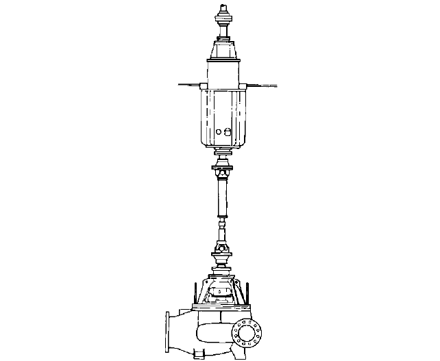
FIGURE 13A Horizontal centrifugal cargo pump with jackshaft (Flowserve Corporation)
In a typical recirculation-priming system, a recirculation tank is mounted between the
cargo-system suction piping and the inlet to the cargo pump. In addition, one or more
priming valves are mounted in the cargo discharge line near the outlet from the pump.
Also, a recirculation line is connected from these valves back to the recirculation tank at
the pump’s inlet, a check valve is installed in the cargo-pump discharge piping above and
9.240 CHAPTER NINE
FIGURE 13B Vertical centrifugal cargo pump with jackshaft (Flowserve Corporation)
downstream from the priming valves, and a vent line with a second check valve is con-
nected from the top of the recirculation tank to the cargo-pump discharge line just
upstream of the discharge check valve. A branch from the recirculation tank’s vent line is
ordinarily piped to the vent/stripping connections in the cargo pump’s casing.
At the beginning of a pump-out, the recirculation tank is filled with liquid cargo and
the priming valves are closed. However, if, as the level in the cargo tank being emptied is
reduced, the percentage of gas in the liquid being transferred increases sufficiently for the
cargo pump to lose suction, the priming valves in the discharge line will open. This per-
mits the cargo contained in the discharge line between these priming valves and the dis-
charge check valve, which closes when the flow through it stops, to be returned through
the recirculation line to the recirculation tank. As this liquid drains through the open
priming valves, a vacuum is created in the discharge line. The gas contained in the recir-
culation tank is displaced by the returning liquid and is drawn by the discharge-line vac-
uum through the vent line and into the portion of the discharge piping that has been
evacuated.
As the recirculated liquid cargo enters the recirculation tank, the liquid level within the
tank rises until the submergence of the cargo pump’s impeller is sufficient for the pump to
regain suction.After this occurs, the flow of liquid through the pump will resume, the prim-
ing valves and the check valve in the vent line will close, and the gases that have accumu-
lated in the discharge line will be forced through the discharge check valve. The priming
cycles will continue until enough gas has been removed from the cargo suction line for the
cargo pump to operate normally. As the level in the cargo tank being emptied continues to
be reduced, the amount of gas entering the suction strum will increase, and the cargo
pump will lose suction more frequently. When the amount of liquid remaining in the cargo
tank is not sufficient for the cargo pump to be reprimed, the pump should be stopped.
9.11 MARINE PUMPS 9.241
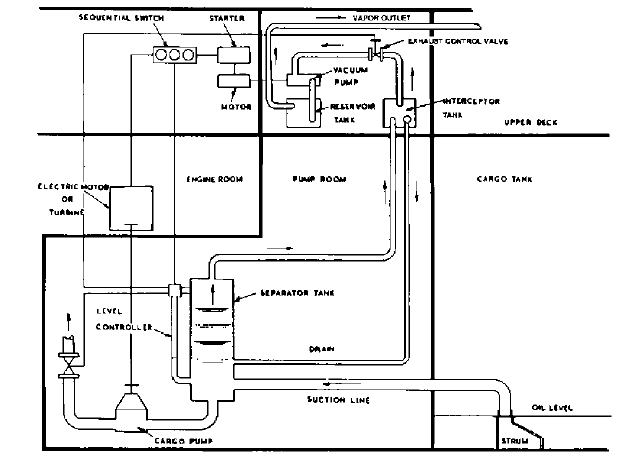
FIGURE 14 Automated-vacuum-stripping system (Flowserve Corporation)
The key components used in a typical automated-vacuum-stripping system (Figure 14)
include a separator tank located at the cargo pump’s inlet, a vent line connected to the top
of the separator tank, an automatic exhaust control valve mounted in the vent line, one or
more electric-motor-driven vacuum pumps, a cargo-pump discharge valve with actuator,
and associated controls. As with the recirculation system, a branch from the separator
tank’s vent line is ordinarily piped to the vent connections in the cargo-pump casing.
At the beginning of a pump-out, the separator tank is ordinarily filled with liquid
cargo. However, as the pump-out progresses, the liquid level in the cargo tank being emp-
tied and the cargo-pump’s suction pressure will both be reduced. Eventually, cargo vapor
will typically begin to accumulate in the top of the separator tank and the liquid level in
the separator tank will drop.At a specified point, the exhaust control valve in the vent line
opens to permit vapor in the separator tank to pass through the vent line before it can
enter the cargo pump. If the venting process is not sufficient, the vacuum pump will start
and draw vapor out of the separator tank.After the vapor has been removed from the sep-
arator tank, the separator-tank liquid level may rise sufficiently for the vacuum pump to
stop and the exhaust control valve to close.The exhaust control valve will, however, reopen
and the vacuum pump will restart automatically if, because of the reaccumulation of vapor
in the top of the separator tank, the separator tank level again drops.The exhaust control
valve will continue to open and close and the vacuum pump will continue to cycle on and
off automatically, as needed, based on the level in the separator tank.
With further reductions in the cargo-tank liquid level, the amount of cargo that vapor-
izes in the cargo-pump suction line and separator tank will increase. In addition, as the
cargo-tank liquid level approaches the suction strum, vortices will typically form on
the surface of the liquid in the cargo tank and draw gas from the tank’s atmosphere into
the suction line. As the percentage of vapor and entrained gas in the liquid cargo being
unloaded increases, the frequency of the exhaust-control-valve/vacuum-pump cycles
described above will increase. Eventually, near the end of the pump-out, it will usually
become necessary for the exhaust control valve to remain open and for the vacuum pump
to operate continuously.
9.242 CHAPTER NINE
In addition to operating the exhaust control valve and the vacuum pump, the
automated-vacuum-stripping system will normally automatically throttle the cargo
pump’s discharge valve whenever the vacuum pump is started. In addition, when permit-
ted by the type of driver used, the cargo pump’s operating speed may be reduced. Controls
may also be included in the system to automatically shut down the cargo pump driver
when the pump-out has been completed.
DEEP-WELL CARGO PUMPS Vertical line-shaft deep-well pumps are used to discharge liquid
cargo on some multi-product and chemical carriers. Therefore, a deep-well cargo pump
must frequently be suitable to transfer a wide range of liquids having different specific
gravities, vapor pressures, viscosities, and temperatures. Some cargoes, such as lubricat-
ing oils, waxes, and other viscous cargoes, may be heated to improve pumpability. With
certain cargoes, such as molten sulfur, steam, or a heated liquid may even be circulated
through jackets that surround the deep-well pump to prevent the cargo from solidifying
within the pump. In addition, deep-well pumps are sometimes used to discharge cryogenic
cargoes, such as liquefied petroleum gas (LPG).
A deep-well cargo pump can be driven by a vertical electric or hydraulic motor mounted
on top of the pump’s discharge head. Alternatively, a deep-well cargo pump may be driven
through a right-angle gear mounted on the discharge head by a horizontal motor, steam tur-
bine, or diesel engine. Although a deep-well cargo pump’s discharge head is often mounted
on a vessel’s main deck, on some vessels, the deep-well-cargo-pump discharge heads are
located below deck in a pump room. In addition, in some cases, a deep-well cargo pump’s
horizontal driver is located in an adjacent space and is coupled to the pump’s right-angle
gear with a jackshaft that passes through a bulkhead separating the pump’s discharge head
from the driver. The opening for the jackshaft in the bulkhead is ordinarily sealed with a
gas-tight stuffing box so the driver can be isolated from any explosive vapor that may be
emitted from the pup. Some designs are also available with submersible motors that allow
the entire pump-driver assembly to be located at the bottom of the cargo tank.
Many deep-well cargo pumps are furnished with a multistage bowl assembly that has
single-suction impellers. When high-vapor-pressure or high-viscosity cargo will be
pumped, an inducer is sometimes mounted on the lower end of the bowl assembly’s
impeller shaft to reduce the pump’s net positive suction head requirements. Alternatively,
a deepwell pump may be fitted with a special low-NPSH first-stage impeller, or, in some
cases, a double-suction first-stage impeller. A spool piece is sometimes installed between
the top of a deep-well pump’s bowl assembly and the lower end of its column assembly so
the bowls can be removed for maintenance while the column and discharge head are still
in place.
Hydraulic axial unbalance resulting from the use of single-suction impellers can result
in the generation of a high axial thrust. Some deep-well pumps are fitted with a balancing
device, such as a balancing drum or front and back impeller wear rings, to reduce this
thrust.Alternatively, a thrust bearing is frequently used to absorb the axial thrust acting on
a deep-well pump’s shaft. This bearing is sometimes installed in a housing that is an inte-
gral part of the pump’s discharge head. In many cases, however, the thrust bearing is in the
vertical driver or right-angle gear (when a horizontal driver is used) that is mounted on top
of the pump’s discharge head. With this latter arrangement, the deep-well pump’s top shaft
is typically secured to the vertical driver or gear either with a rigid coupling when the dri-
ver or gear has a solid shaft or with an adjusting nut when a hollow-shaft driver or gear is
used. It is always important that the pump shaft be raised the proper amount during assem-
bly to prevent contact between the pump’s rotating and stationary parts during operation.
Mating sections of a deep-well pump’s line shaft are typically connected with threaded
or keyed couplings. Radial bearings that support the line shaft are frequently mounted in
brackets, sometimes referred to as spiders, that are sandwiched between mating sections
of column pipe. Impeller- and line-shaft bearings are often lubricated by the pumped
cargo. Consequently, bearing materials must typically be compatible with all of the fluids
that will be pumped. The bearings should also be able to tolerate operation with loss of
suction if the deep-well pump will be used for stripping or during tank cleaning.Although
bronze bearings are common, bearings constructed from carbon, polytetrafluoroethylene
(PTFE) compounds, and various composites and plastics have also been used.
9.11 MARINE PUMPS 9.243
The use of a single shaft seal at the location where a deep-well pump’s top shaft pen-
etrates the discharge head is sometimes suitable. A multiple sealing arrangement con-
sisting of two packed stuffing boxes or a double mechanical seal may be utilized, however,
when a deep-well pump will discharge a volatile cargo. In addition, if a deep-well pump
is fitted with a double mechanical seal, a static seal may also be provided to prevent
vapor from escaping around the pump’s shaft during periods when the mechanical seals
are being replaced. A reservoir tank that stores liquid for seal lubrication is often
mounted on the side of the discharge head of a deep-well pump that has one or more
mechanical seals.
On some multi-product and chemical carriers, a separate deep-well pump is installed
in each cargo tank. This arrangement eliminates the need for suction piping, and it can
result in a high degree of cargo segregation. On a double-bottom vessel, the deep-well
pump’s suction opening is frequently submerged in a suction well located in the bottom of
the cargo tank. In-tank supports are often provided to stabilize the pump during periods
of pitch and roll. However, to prevent these supports from restricting thermal expansion
and distorting a pump’s column or line shaft as a vessel flexes, they are generally not
rigidly attached to the pump.
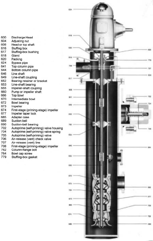
To prevent fluid in a deep-well pump’s discharge head, column pipe, and bowl assem-
bly from draining back into a cargo tank after the pump is stopped, a deep-well cargo
pump’s inlet opening is sometimes fitted with a nonreturn suction valve (Figure 15). Dur-
ing normal operation, the valve is open. However, after the discharge cycle has been com-
pleted, the suction valve closes automatically. The deep-well pump’s driver is then stopped,
the pump’s above-deck discharge valve is closed, and compressed air or inert gas is
injected into the pump through a connection in the discharge head. The gas forces the
cargo contained within the deep-well pump out through a bypass line connected to the
lower portion of the bowl assembly and into the vessel’s piping.
On some vessels, such as those that carry either a limited number of different cargoes
or cargoes that are not sensitive to contamination, each deep-well pump may be used to
discharge cargo from several of the vessel’s tanks. When this arrangement is used, each
deep-well pump is generally mounted in a suction tank or can that is connected to multi-
ple cargo tanks via suction piping.
A deep-well cargo pump that is installed in a suction can is frequently fitted with auto-
matic priming valves that enable the pump to remove gas and vapor from the can and
from the attached suction piping. The operation of these priming valves and their associ-
ated components is often similar to the operation of the recirculation system used to
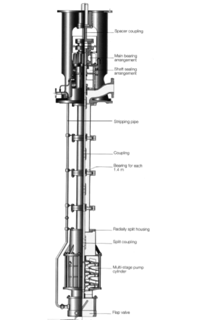
reprime centrifugal cargo pumps.A typical self-priming deep-well pump is fitted with two
or three priming valves that are mounted in the pump’s column pipe just above the bowl
assembly (Figure 16). When the pump is discharging fluid, these valves are closed. How-
ever, when the deep-well pump loses suction, the priming valves open and permit the liq-
uid contained within the pump’s column and discharge head to drain into the suction can.
As this liquid drains through the open priming valves, a vacuum is created in the discharge
head and column pipe. The gas in the bottom of the can, which is displaced by the return-
ing liquid, is drawn by the vacuum through a vent line that is connected from the top of
the suction can to the pump’s discharge head and into the evacuated portion of the dis-
charge head and column.When the liquid level in the suction tank rises sufficiently for the
deep-well pump to regain suction, the flow of liquid through the pump resumes, the prim-
ing valves and a check valve in the vent line close, and the gases that have been drawn
into the column and discharge head are forced out through a check valve installed at the
pump’s discharge connection. The priming cycles will continue until enough gas has been
removed from the cargo suction line for the deep-well pump to operate normally. As the
level in the cargo tank being emptied continues to be reduced, the amount of gas entering
the suction can will increase, and the deep-well pump will lose suction more frequently.
When the amount of liquid remaining in the cargo tank is not sufficient for the deep-well
pump to be reprimed, the pump should be stopped.
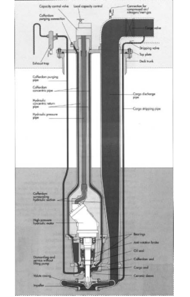
HYDRAULIC-MOTOR-DRIVEN SUBMERSIBLE CARGO PUMPS Hydraulic-motor-driven submersible
pumps are used to discharge cargo on many chemical and multi-petroleum-product car-
riers. In addition, they are used for cargo discharge on some crude carriers. A separate
9.244 CHAPTER NINE
FIGURE 15 Vertical deep-well cargo pump (Svanejoh International A/S)
9.11 MARINE PUMPS 9.245
FIGURE 16 Self-priming vertical deep-well cargo pump (ITT/Gould Pumps, Inc.)
9.246 CHAPTER NINE
pump is usually installed in each cargo tank, which eliminates the need for suction pip-
ing. In addition, to prevent different cargoes carried by a vessel from mixing, each pump
may be connected to an independent above-deck discharge line. Although the pressurized
oil required to drive the hydraulic motors for all of the cargo pumps on a vessel is fre-
quently supplied by a central hydraulic system, a self-contained hydraulic power pack is
furnished for each cargo pump on some vessels.
Each submersible unit usually consists of a single-stage end-suction centrifugal pump
with a short shaft that is driven, often through either a splined connection or a coupling,
by a hydraulic motor (Figure 17). The pump’s shaft is typically supported by antifriction
ball or roller bearings that are submerged in and lubricated by the hydraulic oil that
drains from the motor. The pump is mounted on the lower end of a vertical support pipe
that is suspended from a top plate installed on the vessel’s main deck. The hydraulic-oil
supply and return lines are ordinarily enclosed within this support pipe. Fluid discharged
from the pump’s volute-type casing typically passes through a second vertical pipe that
terminates at an above-deck discharge connection.A control valve that can be used to vary
the flow of hydraulic oil to the motor and, therefore, the pump’s operating speed valve is
usually mounted on the above-deck top plate.
Mechanical or lip-type seals are generally used at the shaft penetrations in a sub-
mersible pump-and-hydraulic-motor assembly to prevent hydraulic oil from leaking into
a cargo tank and to prevent cargo from mixing with hydraulic oil. Air or inert gas can usu-
ally be circulated through a void space or cofferdam that runs through the vertical support
pipe that surrounds the hydraulic supply and return lines, the housing that surrounds the
hydraulic motor, and a chamber between the pump’s seals. After leaving the cofferdam,
this gas frequently passes through an above-deck trap in which liquid is separated so a
hydraulic-oil or cargo-seal leak can be detected. Compressed air or inert gas is also fre-
quently injected into a submersible pump’s above-deck discharge connection after a pump-
out has been completed to force cargo contained within the vertical discharge pipe out
through a small bypass line connected to the base of the pump. However, because a sub-
mersible pump’s inlet is generally not fitted with a nonreturn valve, this operation must
be performed before the driver is stopped.
It is often possible to disassemble a submersible pump and remove it from a cargo tank
for maintenance without disturbing the vertical support pipe or top plate. In most cases,
vessels fitted with hydraulic-motor-driven submersible cargo pumps carry one or more
portable hydraulically driven submersible pumps that can be lowered into a cargo tank
with a winch and used to discharge cargo if the main pump in the tank is inoperable.
In addition to being used for cargo discharge, a submersible cargo pump is sometimes
operated while a vessel is underway to circulate cargo through a diffuser so sediment in
the liquid does not settle in the cargo tank or through an above-deck heater to prevent the
cargo from cooling.Also, to eliminate the need for separate drop lines, on some vessels, liq-
uid is loaded into small cargo tanks by allowing it to flow backwards through a vessel’s
submersible cargo pumps.When this is done, a nonreverse brake is generally mounted on
the submersible pump’s shaft to prevent reverse rotation during loading. However,
because of the resistance created by the pump’s impeller, loading through a submersible
cargo pump can increase loading times.
ELECTRIC-MOTOR-DRIVEN SUBMERSIBLE CARGO PUMPS Electric-motor-driven submersible
pumps are often used to discharge cargo from liquefied natural gas (LNG) and liquefied
petroleum gas (LPG) carriers. Each submersible unit typically consists of a vertical cen-
trifugal pump with either one or two impellers that are mounted on the lower end of an
electric motor’s shaft. In addition, an inducer is often installed at the inlet to the first-
stage impeller (the only impeller in a single-stage pump) to reduce the pump’s net posi-
tive suction head requirements.
Pumps used for cargo unloading are frequently installed directly within a vessel’s
cargo tanks. Cargo typically enters an electric-motor-driven submersible pump through an
opening in the bottom of the pump. After being discharged by the pump’s impellers, the
cargo often enters an annular passage formed between the motor frame and an outer cas-
ing that surrounds the motor. A portion of this liquid usually passes through openings in
the motor frame and flows through the motor. In addition to cooling the motor, this bypass
9.11 MARINE PUMPS 9.247
FIGURE 17 Hydraulic-motor-driven submersible cargo pump (Frank Mohn AS)
flow lubricates the ball bearings that support the common pump and motor shaft. After
leaving the top of the annular passage, the cargo that has been discharged by the pump
passes through a connection located above the motor and enters a vertical pipe that leads
to the main deck.
In addition to the main cargo unloading pumps, smaller spray or cool-down pumps
are often installed on an LNG carrier. When an LNG carrier is unloaded, some cargo is
typically left in each tank. During the voyage back to the loading terminal, the spray
pumps circulate this LNG through a cool-down header and spray nozzles in each tank.
The LNG vaporizes as it passes through the spray nozzles and absorbs heat from the
cargo tanks.This enables the tanks to be kept cold until the vessel is reloaded with addi-
tional cargo.
ROTARY CARGO PUMPS Some vessels that carry high-viscosity cargoes have multiple-screw-
or lobe-type rotary main cargo unloading pumps. In addition, vessels that have centrifugal-
type main cargo pumps sometimes also have lower-capacity screw, lobe, or sliding-vane
pumps that are used to strip cargo tanks.
A rotary main cargo or stripping pump may be installed in a pump room located in the
lower part of a vessel. With this arrangement, the pump can typically take its suction from
multiple cargo tanks through interconnected suction piping. So the driver can be isolated
from explosive vapor in the pump room, it is frequently installed in an adjacent space and
is coupled to the pump with a jackshaft that passes through a bulkhead stuffing box. A
typical rotary cargo pump is driven either by a variable-speed driver or by a constant-
speed driver through a fluid coupling, which enables the pump speed and, therefore, the
capacity delivered to be changed during a pump-out.
Some multiple-screw rotary cargo pumps are furnished in a deep-well configuration
(Figure 18), which can eliminate much of the suction piping in a cargo system. Although
a vertical driver can be used to drive a deep-well rotary pump, many deep-well rotary
pumps are driven through right-angle gears by horizontal motors or engines to facilitate
maintenance and reduce vertical height requirements. Typically, the output shaft of the
above-deck vertical driver or right-angle gear is connected to the power rotor in the pump
through a line shaft that is enclosed within a vertical column pipe. Cargo discharged by a
deep-well rotary pump may pass through the column, or it may pass through a separate
vertical pipe mounted adjacent to the column. Bearings that support the line shaft,
together with the pump’s bearings and timing gears, when used, are sometimes lubricated
by the pumped fluid. Alternatively, a deep-well rotary pump may be furnished with a pres-
surized forced-feed lubrication system.
RECIPROCATING CARGO PUMPS
Direct-acting reciprocating pumps are used to strip cargo
tanks on some vessels.These units typically have double-acting pistons in both the liquid-
and the drive-endcylinders. Some reciprocating stripping pumps are mounted in a pump
room and are connected to the vessel’s cargo tanks through suction piping. With this
arrangement, one pump can be used to strip multiple tanks. Pumps installed in this fash-
ion are frequently duplex units (that is, two liquid cylinders) that are mounted vertically
and are driven by steam (Figure 19).
When used on multi-product carriers, a separate reciprocating stripping pump may be
used for each cargo tank. These stripping pumps are frequently driven by compressed air
or inert gas. On some vessels, a horizontal duplex reciprocating pump is mounted in the
bottom of each cargo tank. Alternatively, a vertical simplex (that is, one liquid cylinder)
pump with a liquid cylinder that is submerged within a cargo tank and a drive cylinder
that is mounted on deck is sometimes used. With this latter configuration, the liquid-end
piston is coupled to the piston in the drive cylinder through a long intermediate shaft.
INERT-GAS SYSTEM PUMPS To reduce the risk of explosion and fire, the space in a cargo tank
above a flammable liquid must typically be kept filled with an inert gas. Some vessels use
flue gas from either a fossil-fueled steam boiler or a dedicated oil-fired inert-gas genera-
tor to inert cargo tanks. A pump is usually required to deliver seawater to a scrubber
where the water is used to cool, clean, and desulfurize the inert gas. A separate pump is
also frequently required to supply seawater to a wet-type deck seal that is used to pre-