Pump Handbook by Igor J. Karassik, Joseph P. Messina, Paul Cooper, Charles C. Heald - 3rd edition
Подождите немного. Документ загружается.

9.11 MARINE PUMPS 9.219
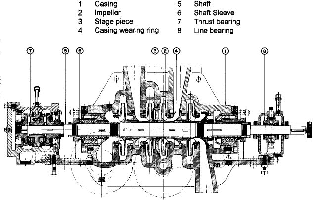
FIGURE 5 Flex-coupled multistage centrifugal main feed pump (Flowserve Corporation)
Motor-driven feed pumps may have grease-lubricated external bearings. Bearings in a
turbine-driven feed pump, however, are usually lubricated with oil that is circulated by a
shaft-driven rotary pump. Oil discharged by this pump also ordinarily lubricates the tur-
bine’s bearings and may be used in the pump’s governor. A strainer, filter, and seawater-
cooled heat exchanger are often installed in the lubricating-oil system. The lubricating oil
used with the turbine-driven feed pumps on many steam-turbine-propelled vessels is the
same grade of oil used in the main propulsion lubricating-oil system.
Although packed stuffing boxes are used to seal shaft penetrations in many marine
feed pump casings, to reduce stuffing-box leakage, some feed pumps are fitted with
mechanical seals. In addition, a condensate-injection shaft seal consisting either of a non-
rotating labyrinth-type fixed breakdown bushing or a series of spring-loaded floating rings
that are stacked axially is sometimes used. When a feed pump that has a condensate-
injection shaft seal is operating, cool condensate is injected into the seal and fills the close
radial clearance between the nonrotating seal parts and a rotating shaft sleeve. A small
portion of this condensate may flow into the pump.The remainder, however, flows outward
and enters a collection chamber that is usually piped back to the vessel’s gland-exhaust
condenser.
During constant-speed operation, the capacity of water delivered to a boiler by a main
feed pump is typically controlled by the throttling action of an automatic feedwater-
regulating valve. However, when steam is used to drive a feed pump, the amount that the
regulating valve must be throttled is often reduced by controlling the amount of steam
supplied to the pump’s driver and, therefore, the pump’s operating speed with either a
constant-pressure or a constant-differential-pressure governor.
A constant-pressure governor automatically regulates a feed pump’s operating speed
to maintain a constant pressure at the pump discharge. If there is a reduction in the boiler
load and the feedwater-regulating valve begins to close, the feed pump’s discharge pres-
sure will rise and the capacity of feedwater that the pump delivers to the boiler will be
reduced. The constant-pressure governor, however, will sense the rise in discharge pres-
sure and will reduce the pump’s speed until this pressure returns to the desired value. As
a result of the speed reduction, the amount that the regulating valve must close to limit
the feedwater flow rate is reduced. An increase in boiler load has the opposite effect.
9.220 CHAPTER NINE
A constant-differential-pressure governor (sometimes referred to as an excess-pressure
governor) regulates a steam-driven feed pump’s operating speed to maintain a set differ-
ence between the pump discharge pressure and the pressure on the boiler-side of the
feedwater-regulating valve. Because changes in the feed flow entering the boiler result,
primarily, from variations in pump speed, the throttling action of the feedwater regulating
valve is greatly reduced.
A relief valve is often installed on the discharge side of a main feed pump to protect the
feed system from overpressurization. In addition, to prevent a feed pump from operating
with too low a capacity, which could occur when the boiler load is low, a recirculation line
is typically connected from the pump discharge to the DFT. An orifice is typically installed
in the recirculation line to limit flow and to reduce the pressure of the water being recir-
culated to match the pressure in the DFT. A valve that can be closed during high-load
operation is also frequently mounted in a feed-pump recirculation line.
Steam turbines that are used to drive feed pumps are generally protected with low-
lubricating-oil-pressure, overspeed, and high-turbine-exhaust-pressure trips. In addition,
a low-suction-pressure trip is sometimes provided to prevent a feed pump from operating
with too low a suction pressure, which can result in cavitation, overheating, and a loss of
load on the pump’s driver.
In addition to the main feed pumps, a smaller capacity feed pump is also installed on
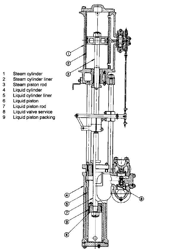
some steam-powered vessels for use in port or during emergencies. Steam-driven direct-
acting piston-type (Figure 6) and motor-driven plunger-type reciprocating pumps, either
vertically or horizontally mounted, are often used for in-port feed service.
Because the feedwater removed from a DFT is normally at its vapor pressure, the net
positive suction head (NPSH) available to a main feed pump is essentially equal to the ele-
vation of the water level within the DFT above the feed pump, less losses in the feed-pump
suction line. On a vessel where the elevation of the DFT is not sufficient to provide an ade-
quate NPSH to the main feed pumps, separate electric-motor-driven centrifugal-type
booster pumps are typically installed between the DFT and the main feed pumps. The
booster pumps, which operate in series with but at a much lower speed than the main feed
pumps, raise the pressure of the feed water entering the main pumps and, therefore,
reduce the potential for cavitation.
MAIN CONDENSATE PUMPS
A typical main condensate pump takes suction from the hotwell
in a main condenser and discharges condensate, through various heat exchangers, to a
deaerating feed tank (DFT). Vertically mounted centrifugal pumps with two or more
stages are frequently used in this application. Although many of these pumps are driven
by electric motors, some main condensate pumps are driven through reduction gears by
steam turbines. Two condensate pumps are generally provided for each main condenser,
with each pump sized to handle full-load requirements.
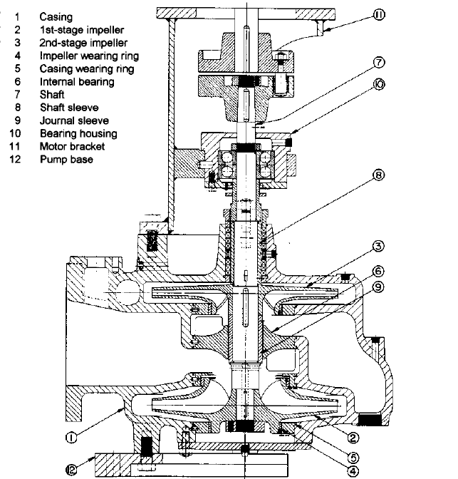
A typical two-stage condensate pump (Figure 7) is fitted with grease-lubricated ball
bearings at the upper end of its shaft to absorb both axial and radial loads. In addition, an
internal water-lubricated radial sleeve bearing is often installed between the two
impellers. The first-stage impeller is usually mounted near the lower end of the shaft,
which increases its submergence. In addition, its suction eye is directed upward, which
enables the impeller to be self-venting. To help facilitate the removal of any air that may
enter the pump, a vent line is ordinarily connected from the suction side of a condensate
pump’s casing to the upper portion of the condenser. The second-stage impeller is ordi-
narily mounted near the upper end of the condensate-pump shaft with its suction eye
directed downward. With this orientation, the hydraulic axial thrust applied the second
stage impeller opposes the axial thrust acting on the first-stage impeller, and the net axial
load that must be absorbed by the pump’s thrust bearing is reduced. In addition, conden-
sate at the base of the shaft seal has already passed through both impellers and is, there-
fore, at an elevated pressure. This helps to prevent air from being drawn into the pump
through the shaft seal. The effectiveness of the shaft seal, which can consist of a packed
stuffing box or a mechanical seal, is also frequently increased by injecting pressurized con-
densate recirculated from the pump’s discharge into the seal area.
The condensate removed from a condenser’s hotwell is normally at or close to its vapor
pressure. Consequently, the net positive suction head (NPSH) available to a condensate
9.11 MARINE PUMPS 9.221
FIGURE 6 Simplex direct-acting reciprocating in-port feed pump (Flowserve Corporation)
pump is essentially equal to the height of the water level in the hotwell above the pump’s
first-stage impeller, which is seldom more than a few feet, less frictional losses in the suc-
tion piping.To help increase the NPSH available to main condensate pumps, they are ordi-
narily installed as low in a vessel as is practicable. They also frequently have special
low-NPSH first-stage impellers.
If a condensate pump is driven by a steam turbine or by a variable-speed electric motor,
its operating speed can be adjusted with plant load. This allows the capacity at which con-
densate is removed from the hotwell to match the rate at which steam is exhausted into
9.222 CHAPTER NINE
FIGURE 7 Two-stage centrifugal main condensate pump (Flowserve Corporation)
the condenser. This is usually accomplished by means of water level control.Alternatively,
when a constant-speed driver is used, the capacity delivered by a main condensate pump
is sometimes regulated by cavitation, which is referred to as submergence control. When
submergence control is utilized, a reduction in plant load will typically result in a reduc-
tion in the main-condenser hotwell level and, therefore, in the NPSH available to the con-
densate pump. After the NPSH available drops below the condensate pump’s NPSH
requirement, the capacity being removed from the hotwell will be reduced by cavitation
within the pump. As the hotwell level continues to drop, the amount of cavitation occur-
ring will increase, and the pumped capacity will continue to be reduced until it eventually
matches the rate at which steam is entering the condenser. When this occurs, the water
level in the hotwell will stabilize at an elevation where the NPSH available to the con-
densate pump is equal to the pump’s NPSH requirement at the new reduced capacity
being pumped. Pumps designed to operate with submergence control need to be of robust
construction and low energy level (per stage) to prevent damage from cavitation and
cavitation-induced vibration.
To avoid operation with excessive cavitation, the capacity delivered by a constant-
speed condensate pump can be regulated by throttling the pump’s discharge valve as
9.11 MARINE PUMPS 9.223
needed to maintain a constant condenser-hotwell level. However, when steam-jet air ejec-
tors are used to deaerate a condenser, condensate-pump operation at too low a capacity
can result in insufficient cooling in the ejector inter- and after-condensers. In addition, low-
capacity operation can lead to surging caused by suction and discharge recirculation
within a condensate pump. To prevent these problems from occurring and to reduce the
need to throttle a condensate pump’s discharge valve, a recirculation line back to the con-
denser is frequently used. This line is connected to a tee in the condensate-pump discharge
piping, downstream from any air-ejector and gland-exhaust condensers. With this
arrangement, if the hotwell level drops, a valve in the recirculation line can be opened,
either manually or automatically, to permit a portion of the water discharged by the con-
densate pump to be returned to the condenser. The hotwell level can be maintained, there-
fore, at a value that is sufficient to suppress cavitation. In addition, because the
condensate pump can always operate at or near its rated capacity, low-flow operation is
avoided. Furthermore, an adequate flow of condensate through air-ejector condensers,
when used, and a vessel’s gland-exhaust condenser can be maintained during plant start-
up and low-load operation. In some cases, the condensate-recirculation line may also be fit-
ted with a thermostatically-controlled valve that opens and permits the condensate flow
rate through the air-ejector condensers to increase when the temperature of the conden-
sate leaving these heat exchangers exceeds a pre-set value.
CONDENSER-EXHAUSTING PUMPS Electric-motor-driven liquid-ring vacuum pumps are some-
times used instead of steam-jet air ejectors to deaerate a main condenser. The vacuum
created by a liquid-ring vacuum pump is limited by the vapor pressure of the liquid com-
pressant (water) within the pump’s casing, which increases with temperature. Therefore,
water separated from the gases discharged by a liquid-ring condenser-exhausting pump
is generally cooled in a heat exchanger before being returned to the pump. Two pumps
that are each capable of maintaining the required vacuum during full-load plant opera-
tion are frequently provided for each main condenser.
FRESHWATER-DRAIN-COLLECTING-TANK PUMPS
A freshwater-drain-collecting-tank (FWDCT)
pump (also sometimes referred to as an atmospheric-drain-tank pump) typically trans-
fers condensate (collected from uncontaminated drains that are above atmospheric
pressure) from a freshwater-drain-collecting tank to a deaerating feed tank (DFT). Elec-
tric-motor-driven single-stage centrifugal pumps are often used in this application. Two
full capacity pumps are usually provided. With this arrangement, the on-line pump is
often started and stopped automatically by a float control in the drain tank. The conden-
sate removed from a freshwater-drain-collecting tank, which is ordinarily at a tempera-
ture of approximately 200 to 210°F (93 to 99°C), is close to its boiling point. To increase
the net positive suction head (NPSH) available to a vessel’s FWDCT pumps, they are fre-
quently installed as far below the drain tank as practicable.
MAIN CIRCULATING PUMPS On a steam-powered vessel, a main circulating pump delivers
seawater to a main condenser that receives steam exhausted from a propulsion turbine.
In addition, a portion of the seawater discharged by a main circulating pump may be
diverted to other seawater-cooled heat exchangers, such as the main lubricating-oil cool-
ers. After passing through the main condenser or another cooler, the seawater is directed
overboard. In addition to the main suction flange, which is connected to a sea chest, some
main circulating pumps also have an auxiliary side-suction connection that can be used
for emergency dewatering of the machinery space bilge.
Typically, one or two main circulating pumps are provided for each of a vessel’s main
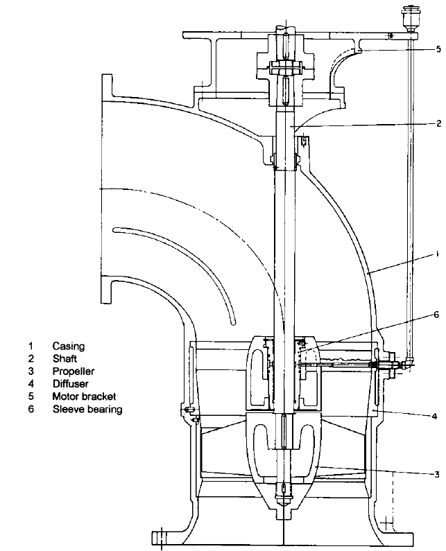
condensers. Single-stage axial-flow propeller pumps (Figure 8) that deliver high flow rates
at relatively low discharge pressures are often used in this application. In many cases, the
pump is not furnished with a thrust bearing. Instead, the pump shaft is rigidly coupled to
the driver’s shaft, and axial loads are absorbed by the driver’s thrust bearing. Radial loads
applied to the pump shaft, however, are generally absorbed by a journal bearing that is
located above the overhung propeller. During operation in harbors and inland waterways,
the water delivered by a main circulating pump will often contain silt, sand, and other
abrasives. Consequently, internal journal bearings that are lubricated by water discharged
9.224 CHAPTER NINE
FIGURE 8 Axial-flow main circulating pump (Flowserve Corporation)
from the propeller are sometimes furnished in abrasion-resistant grades of rubber or com-
posite materials. Alternatively, some main-circulating pump internal bearings are lubri-
cated by grease or clean water supplied through an external connection in the pump’s
casing.
When higher discharge pressures are required, single-stage mixed-flow pumps with
overhung end-suction impellers or single-stage radial-flow pumps with double-suction
impellers mounted between bearings are sometimes used as main circulating pumps.
Main circulating pumps are generally driven either by steam turbines with reduction
gears or by two-speed electric motors. This permits the capacity of seawater discharged
through the condenser to be reduced during system startup and shutdown and other peri-
9.11 MARINE PUMPS 9.225
ods of low-plant-load operation by reducing the speed of the circulating pump’s driver.
Many steam ships are fitted with a scoop-injection system that permits seawater to be
forced through the main condensers by the forward momentum of the vessel. With this
arrangement, the main circulating pumps are usually stopped whenever the vessel is
operating above a certain speed.
FUEL-OIL SERVICE PUMPS A fuel-oil (FO) service pump typically takes suction through
either high- or low-suction ports in the FO service or settling tanks and supplies fuel oil
to the burners in a steam ship’s oil-fired boilers. At least two service pumps each capable
of delivering the vessel’s full-power fuel-oil requirement are generally provided. FO ser-
vice pump suction and discharge lines are generally fitted with duplex strainers. In addi-
tion, one or more flow meters and heaters are frequently installed in a FO service system.
Horizontally and vertically mounted multiple-screw rotary pumps that are driven by
either steam turbines or two-speed electric motors are often used in this application. In
addition, some older ships have steam-driven reciprocating FO service pumps. When a
vessel normally burns heavy (residual) fuel oil, which must be heated before being deliv-
ered to a boiler’s burners, a separate electric-motor-driven rotary pump is also usually pro-
vided to supply unheated distillate fuel oil to the boilers during plant start-up.
The steam flow to a turbine-driven rotary or a direct-acting reciprocating FO service
pump is often regulated with a constant-pressure governor that acts to maintain a con-
stant FO-service-pump discharge pressure. With this arrangement, changes in the flow
rate passing through the FO service pump result from variations in the pump’s operating
speed. When a two-speed electric motor is used to drive a FO service pump, the motor is
ordinarily operated at low speed during low-plant-load periods (for example, in port) and
at high speed during high-plant-load periods. However, during operation at either speed,
a motor-driven FO service pump typically discharges more oil than the amount required
by the burners.The excess oil is usually returned to the suction side of the FO service sys-
tem through a recirculation line. The flow rate through this recirculation line is often reg-
ulated by an automatic valve that maintains a constant FO-service-pump discharge
pressure. An additional recirculation line with a hand-operated valve is frequently pro-
vided to permit fuel oil to be circulated through a FO-service-system heater and a boiler’s
burner manifold prior to lighting-off the boiler. To prevent FO-service-system overpres-
surization, a relief valve should always be installed on the discharge side of each FO ser-
vice pump.
Remote controls are typically provided that enable a vessel’s FO service pumps to be
stopped in an emergency from outside of the machinery space. In addition, flanged FO-
service-pump discharge connections are ordinarily fitted with wrap-around shields to
deflect spray in case of a leak. In addition, a drip pan or similar device is usually installed
under a FO service pump to prevent oil that may leak out of the pump from draining into
a vessel’s bilge.
LUBRICATING-OIL SERVICE PUMPS A lubricating-oil service (LOS) pump removes lubricating
oil from the propulsion-reduction-gear sump and discharges it to the propulsion-turbine
bearings, the reduction gears and their bearings, and the main thrust bearing for each
propulsion shaft. This oil is also usually directed to the inlet side of a speed-limiting gov-
ernor pump mounted on the forward end of each propulsion turbine’s shaft and to the
propulsion-turbine throttle- or nozzle-valve controls. In addition, a portion of the pumped
oil may be sent to an overhead gravity tank that holds enough oil to lubricate the propul-
sion machinery for several minutes following a loss of LOS-pump discharge pressure.
Most steam-powered vessels have two or three LOS pumps. Horizontally and vertically
mounted multiple-screw pumps are frequently used. When mounted vertically, the pumps
may be submerged directly within the lubricating-oil (LO) sump. In most cases, at least
one rotary LOS pump is electric-motor-driven. Remaining units may also be motor driven,
or they may be driven by steam turbines or off the propulsion shafting. In addition, steam-
driven reciprocating-piston pumps are sometimes used as standby LOS pumps. In addi-
tion, some vessels have a battery-operated emergency LOS pump.
LOS pumps are typically installed low in a vessel and close to the LO sump. Suction
and discharge lines are often fitted with duplex strainers. In addition, a relief valve and
9.226 CHAPTER NINE
coolers are generally installed in pump discharge lines. Also, one or more orifices are typ-
ically installed in a LOS system to reduce the pump’s full discharge pressure, which is usu-
ally based on the requirements of the propulsion-turbine governors and controls, down to
the pressure required by the bearings and gears. A pressure-controlled switch or valve
that automatically starts a standby pump if the oil pressure at the discharge of the oper-
ating LOS pump drops below a preset value is often provided. Most steam-turbine-
propelled vessels also have a device that stops the supply of steam to the ahead propulsion
turbines in case of a LOS-system failure.
DIESEL-PROPELLED VESSELS_________________________________________
A propulsion diesel engine that operates below approximately 300 rpm and is directly con-
nected to a propulsion shaft is usually classified as a slow-speed engine. Diesel engines
that are connected to propulsion shafts through reduction gears and have maximum oper-
ating speeds below 900 to 1200 rpm are typically classified as medium-speed engines, and
engines that operate above 900 to 1200 rpm and are used with reduction gears are gener-
ally classified as high-speed engines.
ENGINE FRESHWATER COOLING PUMPS A pump is ordinarily used to circulate freshwater
through jackets in a propulsion diesel engine’s cylinders and cylinder heads, the engine’s
turbocharger, and, on some vessels, an evaporator where the jacket water provides heat
to produce fresh water. The jacket water may also pass through the engine’s lubricating-
oil and charge-air coolers. In addition, a heat exchanger in which the jacket water is cooled
by either freshwater or seawater is frequently included in the system. Alternatively, this
heat exchanger is sometimes eliminated when a vessel has a central freshwater cooling
system. Instead, some freshwater from a separate low-temperature loop is admitted into
the high-temperature jacket-water loop where it mixes with and cools the hot jacket water.
An additional heat exchanger that can be used to preheat the jacket water prior to engine
start-up is often provided as part of a main engine’s jacket-water system.
The pumps that circulate cooling water through a propulsion diesel engine are fre-
quently called jacket-water circulating pumps. Alternatively, however, they may be
referred to as high-temperature freshwater cooling pumps on a vessel that has a central
freshwater cooling system.Two vertically or horizontally mounted single-stage centrifugal
pumps that are each sized to meet normal full-load requirements are often provided for
each propulsion engine. Although each pump may be driven by an electric motor, when
used with a high- or medium-speed propulsion engine, one of the pumps is often mounted
on and driven off the engine.An elevated tank is ordinarily included in the system to allow
for any thermal expansion of the water and to maintain a positive pressure at the pump
suction.
Separate electric-motor-driven pumps may be used to circulate fresh water through a
propulsion engine’s pistons when they are water-cooled.Although single-stage centrifugal
pumps are often used in this application, vertical turbine pumps that are submerged in
the piston-cooling-water drain tank are used on some vessels. When required by the
engine design, an additional pair of electric-motor-driven centrifugal pumps is provided to
circulate fresh water through an independent loop that cools the main-engine fuel valves
or injectors.
ENGINE SEAWATER COOLING PUMPS On some vessels, single-stage centrifugal pumps are
used to supply seawater to diesel-engine charge-air, lubricating-oil, and jacket-water cool-
ers. Two pumps that are each sized to meet normal full-load requirements are often pro-
vided for each propulsion engine. Although both seawater-cooling pumps may be driven
by electric motors, when a medium- and high-speed diesel engine is used, one pump is
sometimes attached to and driven by the engine.
FUEL-OIL SUPPLY AND BOOSTER PUMPS Fuel-oil (FO) pumps used for diesel engines should
be suitable to handle any of the various grades of fuel that may be burned in a vessel’s
9.11 MARINE PUMPS 9.227
engines, which can often include both light distillates that are used during maneuvering
and heavy residual oils that are used while underway at sea. When heavy fuel oil is sup-
plied to an engine, it must generally be heated to reduce its viscosity.
A FO booster pump typically takes suction either directly from a diesel-propelled ves-
sel’s daily service tanks or from a separate mixing tank and supplies fuel oil to the main-
engine injector pumps. Two multiple-screw- or gear-type fuel-oil booster pumps that are
each capable of meeting full-power requirements are often provided for each propulsion
engine. Both FO booster pumps may be electric motor driven.Alternatively, however, when
a medium- and high-speed diesel engine is used, one FO booster pump is sometimes
attached to and driven by the engine. Also, in some high-temperature heavy-fuel-oil sys-
tems, a pair of electric-motor-driven screw- or gear-type FO supply pumps that operate
upstream of and in series with the FO booster pumps are located between the service
tanks and the mixing tank. More oil is typically delivered to an engine than the amount
required for combustion, and the excess oil is ordinarily returned to the service or mixing
tank through a recirculation line. Strainers, filters, flow meters, and heaters are also fre-
quently installed in the FO service system.
LUBRICATING-OIL PUMPS The main-engine lubricating-oil (LO) pump typically removes
lubricating oil from a sump located below a propulsion engine and discharges the oil to
the engine’s bearings, governor controls, turbochargers, and, when they are cooled by oil,
the engine’s pistons. Strainers, filters, and a cooler are also usually included in a LO sys-
tem. Two main LO pumps that are each capable of delivering the oil required during nor-
mal full-load engine operation are usually provided for a propulsion engine. Vertically or
horizontally mounted multiple-screw and gear pumps are frequently used in this appli-
cation. Although both pumps may be driven by electric motors, one pump is sometimes
attached to and driven off a medium- or high-speed engine. Alternatively, some vessels
have electric-motor-driven vertical turbine pumps that are submerged within the LO
sump installed. A device that sounds an alarm following a failure of the LO system is nor-
mally provided.
When a vessel is propelled by a crosshead-type diesel engine, some of the oil discharged
by the main LO pump is often directed to the suction-side of a lower-capacity rotary-type
booster pump that supplies oil to lubricate the engine’s crosshead bearings. In addition, a
separate low-capacity rotary pump is frequently required to fill a head tank that supplies
a different grade of oil to lubricators that inject the oil into each of a crosshead engine’s
cylinders. Also, with some designs, a separate pair of rotary pumps is required to supply
lubricating oil to the engine’s camshaft bearings.
In addition to the pumps that supply lubricating oil to propulsion engines, separate
rotary pumps are generally used to supply lubricating oil to reduction gears and their
bearings on vessels propelled by medium- or high-speed engines.
GAS-TURBINE-PROPELLED VESSELS___________________________________
FUEL-OIL SERVICE PUMPS Typically, fuel oil is delivered to a propulsion gas turbine’s com-
bustion-chamber nozzles by a gear pump that is mounted on and driven by the gas tur-
bine. In addition, a pair of two-speed electric-motor-driven rotary pumps that operate
upstream of and in series with the attached pump are usually provided. Duplex strainers,
filters, and heaters are also ordinarily included in a gas turbine’s fuel-oil service system.
LUBRICATING-OIL PUMPS A typical gas turbine is furnished with an attached gear- or cen-
trifugal-type lubricating-oil (LO) pump that is driven off the gas turbine.This pump takes
suction from a LO reservoir and discharges synthetic oil to the bearings for the gas tur-
bine and to control devices. Filters are also included in the LO system. In addition, electric-
motor-driven gear, vane, or centrifugal pumps are ordinarily used to circulate lubricating
oil through the system during start-up and cool-down periods and to serve as a backup to
the attached pump. Excess oil delivered by a gas turbine’s LO pump is frequently returned
through a pressure regulating valve to the LO reservoir. A device is normally provided
9.228 CHAPTER NINE
that sounds an alarm and, in some cases, automatically stops the flow of fuel to a gas tur-
bine following a failure of the LO system.
Separate rotary scavenge pumps may be used to return oil that drains from a gas tur-
bine’s bearings to the LO reservoir. In addition, multiple-screw pumps are frequently used
to circulate mineral oil through an independent lubrication system for a gas-turbine-
propelled vessel’s reduction gears and their bearings. Although one of these screw pumps
may be driven off the reduction gears, the remaining reduction-gear LO pumps are usually
electric motor driven. Some of the mineral oil in the reduction-gear LO system frequently
passes through a heat exchanger in which it absorbs heat from the synthetic oil that lubri-
cates the gas turbine’s bearings. The reduction-gear lubricating oil also usually passes
through a second heat exchanger in which it is cooled either by freshwater or seawater.
GENERATOR APPLICATIONS __________________________________________
Steam-Turbine-Driven Turbogenerators
AUXILIARY CONDENSATE PUMPS When the steam leaving a steam ship’s turbogenerator
exhausts into an auxiliary condenser, an auxiliary condensate pump is ordinarily used to
remove condensate from the auxiliary condenser’s hotwell and return it to the DFT. A typ-
ical auxiliary condensate pump is a vertical two-stage centrifugal pump that is similar in
configuration to a main condensate pump but is smaller in size. One auxiliary condensate
pump is typically furnished for each auxiliary condenser. Crossover lines are, however,
often provided so each auxiliary condensate pump on a vessel can remove condensate from
any of the vessel’s auxiliary condensers.
AUXILIARY CIRCULATING PUMPS
A single-stage centrifugal pump is often used to circulate
seawater through the tubes of an auxiliary condenser that receives steam exhausted from
a vessel’s turbogenerator. Seawater discharged by this pump may also be directed to the
generator’s lubricating-oil and air coolers. One auxiliary circulating pump is typically fur-
nished for each auxiliary condenser. Crossover lines, however, are often provided so one
generator’s auxiliary circulating pump can supply seawater to any of the vessel’s auxil-
iary condensers. In addition, a line is often installed that permits seawater discharged
from a vessel’s auxiliary circulating pumps to be directed, in case of a main circulating
pump failure, to a main condenser.
LUBRICATING-OIL PUMPS
A typical turbogenerator is fitted with an internal or external
gear-type lubricating-oil (LO) pump that is geared to and driven by the turbine.The pump
ordinarily takes its suction from a sump located below the turbine’s reduction gears and
discharges lubricating oil to bearings, the turbine’s reduction gears, and the governor that
controls the flow of steam to the turbine. A separate hand-operated or electric-motor-
driven gear pump may also be provided to enable lubricating oil to be circulated through
the LO system during generator start-up and shutdown periods.
A duplex strainer, a cooler, and one or more relief valves are often included in a turbo-
generator’s LO system. In addition to protecting the system from overpressurization, the
relief valves act as backpressure valves that maintain the desired LO pressure in various
parts of the system. This arrangement permits lubricating oil sent to the governor to be at
a higher pressure than the oil directed to bearings and reduction gears. A turbogenerator
is ordinarily fitted with a trip that stops the flow of steam to the turbine if the LO pres-
sure drops below a preset value.
DIESEL-DRIVEN GENERATORS_________________________________________
JACKET-WATER CIRCULATING PUMPS A diesel engine that drives a generator is often fur-
nished with an attached centrifugal-type jacket-water circulating pump that circulates