Power electronic handbook
Подождите немного. Документ загружается.

916 M. F. Rahman et al.
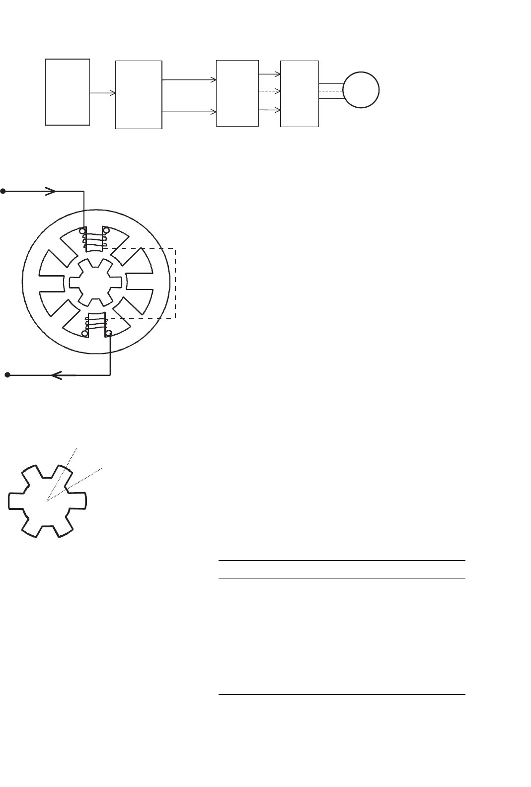
Motion
Controller
Profile
Controller
Translator
Stepping
pulses
Direction
Drive
circuits
Stepper
motor
FIGURE 33.96 Structure of an open-loop motion controller for a stepper motor.
A1
B1
C1
D1
A2
B2
C2
D2
1
2
3
4
5
i
i
+V
dc
O
6
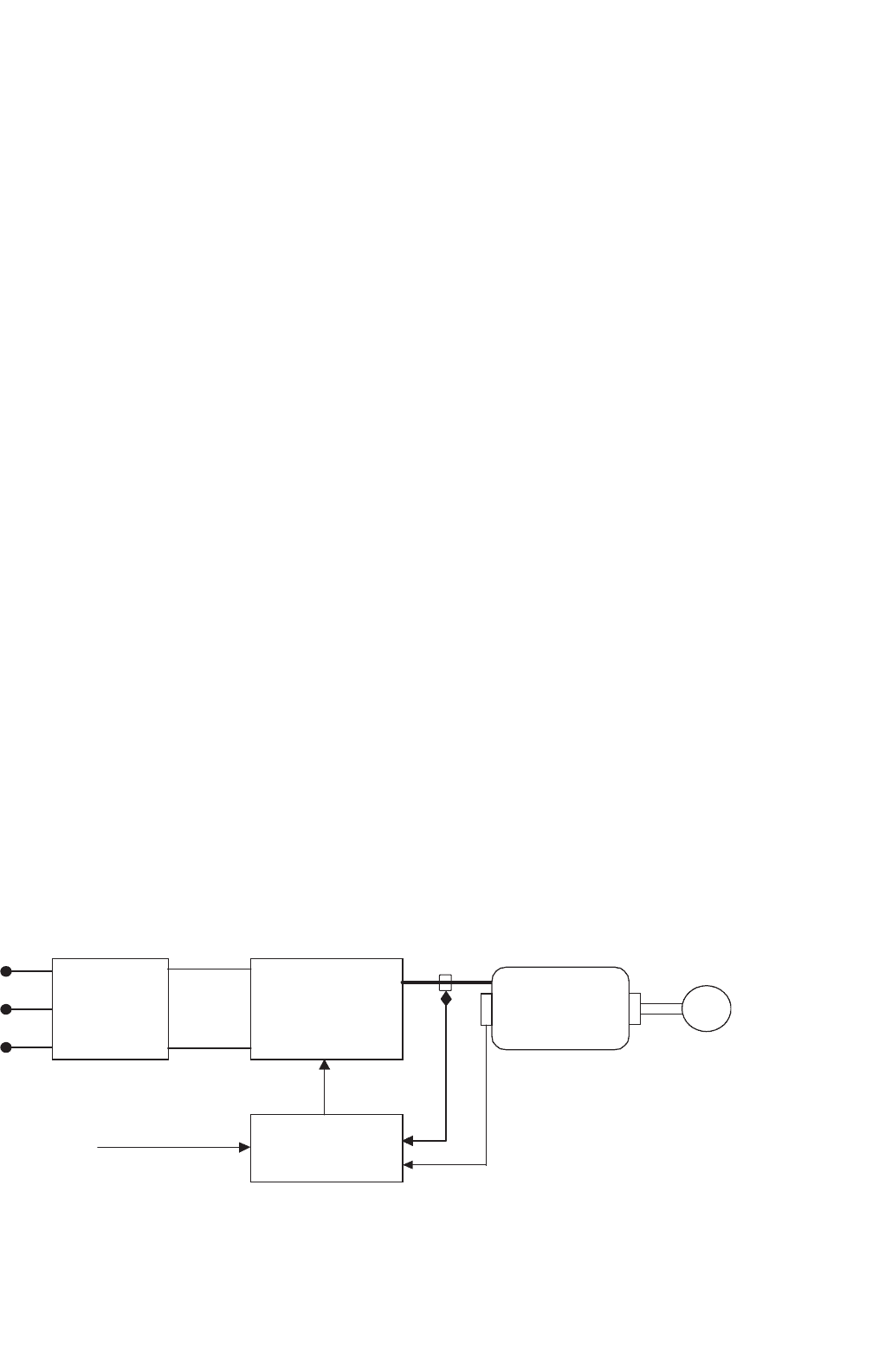
FIGURE 33.97 Four-phase SR motor topology.
Rotor pole center
axis
Inter-pole axis
FIGURE 33.98 Rotor pole axis positions.
stator pole axis. This position corresponds to the position of
minimum inductance. These rotor axis positions are illustrated
in Fig. 33.98.
To achieve continuous rotation, the stator phase currents
are switched on and off in each phase in a sequence according
to the position of the rotor. Consider the motor schematic
illustrated in Fig. 33.97. If coils A1 and A2 of phase A are
excited and produce a magnetic field in a vertical direction,
then poles 1 and 4 on the rotor will align themselves with the
stator poles of phase A. If the coils of phase A now have their
current switched off, and coils B1 and B2 of phase B are now
excited, then in a similar fashion the rotor will move so that
the poles 2 and 5 are aligned with stator poles B1 and B2.
Exciting phases A, B, C, and D in sequence will produce rotor
rotation in the counterclockwise direction.
From the preceding discussion, one may see that the switch-
ing on and off of excitation current to the motor phases is
related to the rotor pole positions. This means that some form
of position sensor is essential for the effective operation of the
SR motor.
33.9.2 Advantages and Disadvantages of
Switched-reluctance Motors
The SR motor has a number of inherent advantages that makes
it suitable for use in certain variable-speed drive applications.
Nevertheless, the motor also has some inherent disadvantages
that must be considered before choosing the motor for a par-
ticular application. In Table 33.6, the main advantages and
disadvantages of the SR motor drive are summarized.
33.9.3 Switched-reluctance Motor
Variable-speed Drive Applications
The main application for SR motors is in variable-speed drive
systems. One application area has been general-purpose indus-
trial drives where speed, acceleration, and torque control are
desired. SR-motor-based industrial drives provide the advan-
tages of a very wide range of operating speeds as well as
TABLE 33.6 Advantages and disadvantages of SR drives
Advantages Disadvantages
Low cost motor. Need for position measurement.
Robust motor construction. Higher torque ripple than other
machine types.
Absence of brushes. Higher noise than other machine types.
No motor short-circuit fault. Nonlinear and complex characteristics.
No shoot-through faults.
Ability to operate with faulted
phase.
High torque to inertia ratio.
Unidirectional currents.
High efficiency.
33 Motor Drives 917
high efficiency and robustness. Other applications of the SR
drive include automotive applications, where the SR motor has
advantages of robustness and fault tolerance. The SR motor in
this application can also be easily controlled for acceleration,
steady speed, and regenerative braking.
The SR motor is also well suited to aerospace applications
where the ability to operate under faulted conditions and its
suitability for operation under harsh environments are critical.
Additionally, the very high-speed capability and high-power
density also make these motors well suited in the aerospace
field. There are also many domestic appliances where cost is of
primary concern. In these products, the SR motor can provide
a low-cost solution for a brushless fully controllable motor
drive. In addition, the motor can be used in battery-powered
applications, where the motor-high efficiency and ability to
use a dc supply are important.
33.9.4 SR Motor and Drive Design Options
The main components of the drive system are shown in
Fig. 33.99. It is important to design the motor and drive
together in an integrated manner. The main criteria that need
to be considered in designing the components of the SR drive
system will be discussed later. It will be seen that certain design
choices, which may be advantageous for one component of
the drive system, may bring about disadvantages in another
component. This highlights the need for a careful, integrated
system approach to be taken when designing the drive system.
33.9.4.1 Number of Motor Phases
There are many possibilities in choosing the number of stator
phases and rotor poles in SR motors. The simplest SR motor
may consist of only one phase; however, to operate the motor
in four quadrants (motoring or generating in both forward
or reverse directions), at least three phases are required. The
most common configuration to date has been the four-phase
SR motor, which has eight rotor poles and six stator poles, as
was shown in Fig. 33.97.
3 Phase
AC Mains
Controlled or
Uncontrolled
Rectifier
Inverter
Controller
SR Motor
Load
DC link
Measured
Currents and
Voltages
Position Feedback
Input Commands
FIGURE 33.99 Main components of an SR drive.
33.9.4.2 Maximum Speed
The SR motor is capable of operating at very high speeds
because of its robust rotor construction, and in most applica-
tions the maximum speed is limited by the inverter switching
speed and not limited by the motor itself. The maximum speed
of the SR motor is itself normally greater than 15,000 rpm for
a standard SR motor.
However, to determine the maximum drive speed, the con-
troller and motor must be considered together. This is because
the power-electronic device switching speed is directly pro-
portional to the commutation frequency, which is in turn
proportional to the motor speed. The maximum switching
frequency of the power devices must therefore be taken into
account in the SR drive design.
33.9.4.3 Number of Power Devices
In general, the number of switches per phase in SR motor
drives will vary according to the inverter topology. A wide
range of different SR drive circuits are available for SR drives,
and these are detailed below. Circuits with only one switch
per phase are possible; however, these have various disadvan-
tages such as control restrictions, a need for extra windings,
or higher switch voltages. However, with two switches per
phase, the motor is fully controllable in four quadrants and has
completely independent motor phase control. Therefore, the
maximum number of power switches required for the motor
operation is normally 2q, where q is the number of phases.
33.9.4.4 Inverter Topology Types for SR Motors
As was mentioned, the torque produced in the SR motor is
independent of the direction of current flow in each motor
phase. This means the inverter is only required to supply uni-
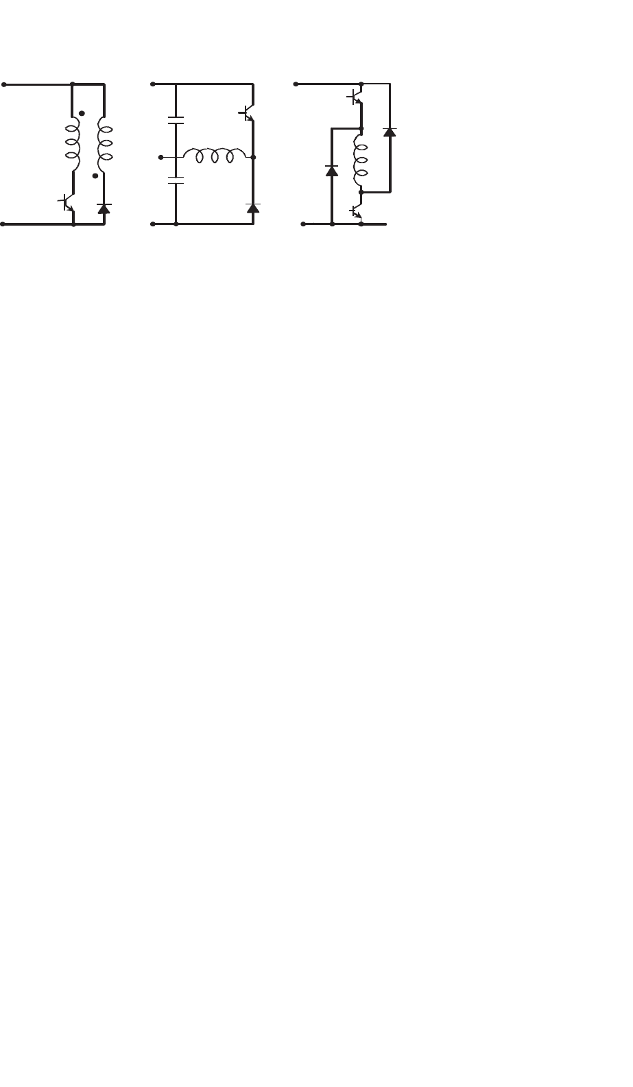
directional currents into the stator windings. The three major
circuit topology types that have been used for each winding
of an SR motor drives are shown in Fig. 33.100. As indicated
in this figure, these are commonly termed the bifilar, split dc
supply, and two-switch type inverter circuits.
918 M. F. Rahman et al.
+
−
+
−
(
a
)(
b
)(
c
)
+
−
FIGURE 33.100 Major SR inverter topology types: (a) bifilar type; (b) split dc supply type; and (c) two switch type.
In the circuits shown in Fig. 33.100, only one or two switch-
ing components per phase are required. Other circuit topology
types that use shared components between the motor phases
have limitations in control flexibility.
33.9.4.4.1 Bifilar Type Inverter Circuit In Fig. 33.100a, a
drive circuit for a bifilar-wound SR motor is shown. The bifilar
windings are closely coupled, with one winding being con-
nected to a switching device while the other is connected to a
freewheeling diode. Current is increased in the winding when
the switching device closes. At turn-off, the current transfers
to the secondary winding through transformer action, and the
inductive energy flows back into the supply via the freewheel-
ing diode. If perfect coupling is assumed, then the voltage
across the switching device will rise to twice the dc supply volt-
age during turn-off. However, in practice this would be higher.
This is because there will be some uncoupled inductance in the
primary that will cause high induced voltages when the cur-
rent in the winding collapses to zero. Thus, snubbing circuits
would almost certainly be required to protect the switching
components from over-voltage.
The advantage of the bifilar circuit is that it requires only
one switching device per phase. However, with the advent of
modern power electronic devices, which have both low cost
and low losses, this advantage quickly disappears.
33.9.4.4.2 Split DC Supply Inverter Circuit The split dc
supply type inverter circuit is in Fig. 33.100b. As in the bifilar
circuit, this configuration also uses only one switching device
and one diode per phase. However, a center-tapped dc source
is required. When the switching device is turned on, current
increases in the phase winding because of the positive capaci-
tor voltage being applied. At turn-off, the current is forced to
flow through the diode and thus decays to zero more quickly
because of the connection to the negative voltage. It is usual
for the dc center tap to be implemented using a split capac-
itor in the dc-link. The voltages across each capacitor must
remain balanced, which means that there can be no significant
power-flow difference between the two capacitors.
Upon examination of the circuit, it can be seen that because
of the split capacitor bank, only half the available dc voltage
can be switched across the phase winding. Thus, for the same
voltage across the motor phases that is supplied by the bifilar
circuit described earlier, the dc supply voltage must be doubled
with respect to the bifilar circuit supply. This means that the
voltage rating of the devices would effectively be the same as
in the bifilar circuit.
This is inherently inefficient. The configuration also has the
need for balanced split capacitive components. In addition, it
will be seen that the soft-chopping form of control described in
Section 33.9.7 is not available in this drive.
33.9.4.4.3 Two-switch Inverter Circuit The two-switch
inverter type circuit, which is shown in Fig. 33.100c, uses
two switching devices and two diodes per phase. Unlike the
previous two circuits, three modes of operation are possible:
Mode 1: Positive phase voltage
A positive phase voltage can be applied by turning both switch-
ing devices on. This will cause the current to increase in the
phase winding.
Mode 2: Zero phase voltage
A zero-voltage loop can be imposed on the motor phases
when one of the two switches is turned off while current is
flowing through the phase winding. This results in current
flow through a freewheeling loop consisting of one switch-
ing device and one diode, with no energy being supplied by
or returned to the dc supply. The current will decay slowly
because of the small resistance of the semiconductors and con-
nections, which leads to small conduction losses. This mode
of operation is used in soft-chopping control, as described in
Section 33.9.7.
Mode 3: Negative phase voltage
When both switches in a motor phase leg are turned off, the
third mode of operation occurs. In this mode, the motor phase
current will transfer to both of the freewheeling diodes and
33 Motor Drives 919
return energy to the supply. When both of the diodes in the
phase circuit are conducting, a negative voltage with amplitude
equal to the dc supply voltage level is imposed on the phase
windings.
In this circuit, the switching devices and diodes must be able
to block the dc supply voltage amplitude when they are turned
off, in addition to any switching transient voltages. However,
because the circuit contains two devices in series, the blocking
voltage is essentially half the value seen in the previous two
circuit types for the same applied motor phase voltage ampli-
tude. Another advantage of the two-switch inverter circuit is
that it offers greater control flexibility with its three modes of
voltage control.
A disadvantage of this inverter type, as compared to the bifi-
lar and split dc supply types, is that it contains twice as many
switching components per phase. However, with the current
wide availability and economy of power semiconductors, in
most applications, the advantages of the two-switch circuit
outweigh the cost of an extra switching device per phase.
33.9.5 Operating Theory of the
Switched-reluctance Motor:
Linear Model
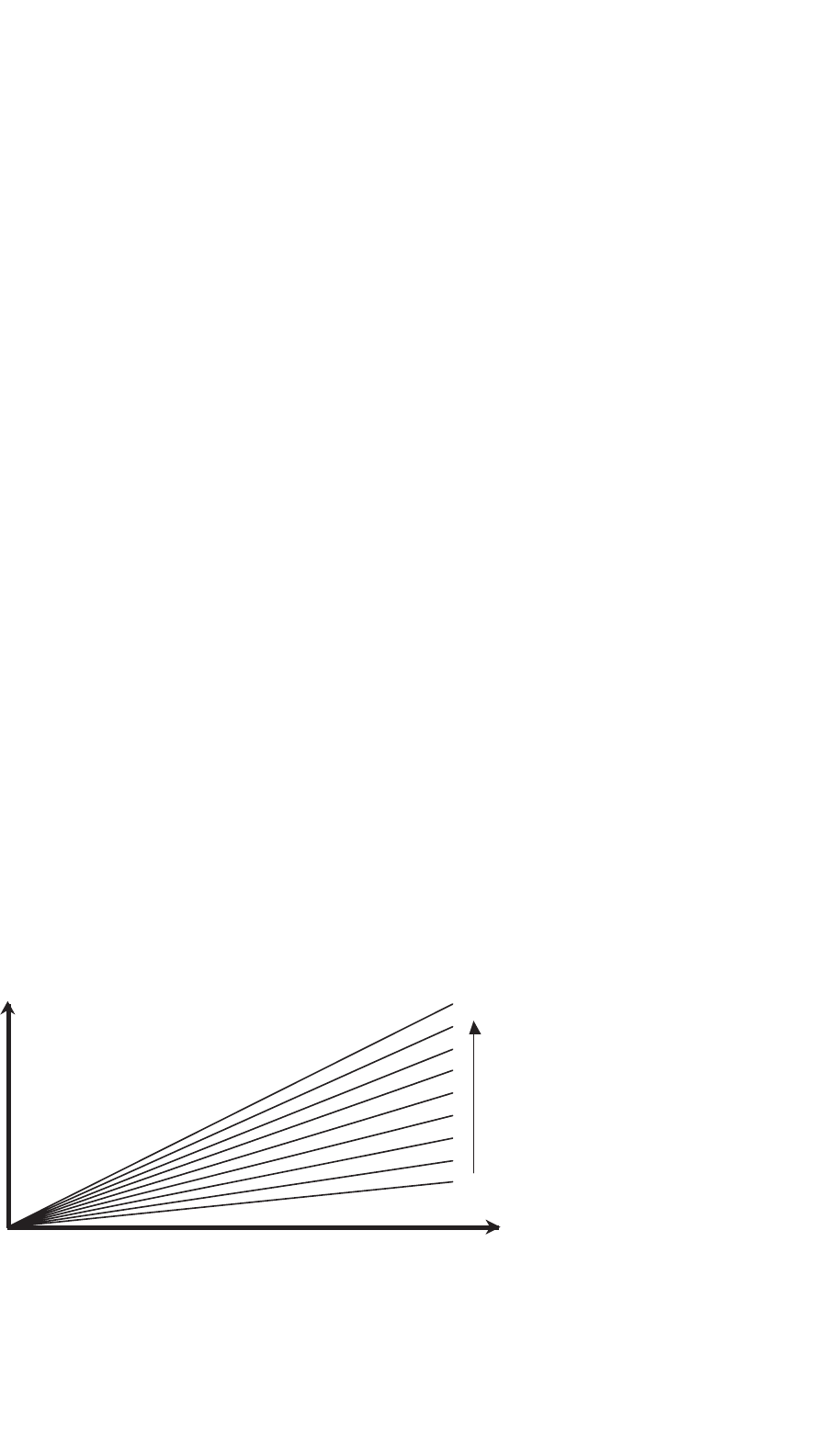
If a linear magnetic circuit is assumed, the flux linkage is pro-
portional to phase current for any rotor position θ. This is
demonstrated in Fig. 33.101, where the magnetization curves
for the linear SR motor for various rotor positions and cur-
rents are shown. In this linear case, the inductance L at any
position θ, which is the slope of these curves, is constant and
independent of current.
As the motor rotates, each stator phase undergoes a cyclic
variation of inductance. As can be seen in Fig. 33.101, in the
fully aligned position (when a rotor pole axis is directly aligned
with the stator pole axis) the reluctance of the magnetic circuit
through the stator and rotor poles will be at a minimum, and
0
Y (Wb)
Rotor
Position
q (degrees)
Unaligned Position
Flux Linkage
Current i (A)
Aligned Position
FIGURE 33.101 Magnetization characteristics of linear SR motor.
thus the inductance of the stator winding will be at a maxi-
mum. The opposite will occur in the fully unaligned position
(when the rotor inter-pole axis is aligned with the stator pole).
Thus, the inductance becomes a function of position only and
is not related to the current level. If it is also assumed that
mutual inductance between the phases is zero, then a typical
inductance variation L(θ) with respect to the rotor position
similar to that shown in Fig. 33.102 arises. Although this is an
idealized inductance variation, it is helpful in the understand-
ing of key operating principles of the machine. One should
note that in the idealized inductance variation there are sharp
corners, which can only arise if flux fringing is completely
ignored.
Four distinct regions can be identified in the plot of the
linear inductance variation shown in Fig. 33.102. These distinct
regions correspond to a ranges of rotor pole positions relative
to the stator pole positions as described below:
Region A
This region begins at rotor angle θ
1
, where the first edge
of the rotor, with respect to the direction of rotation, just
meets the first edge of the stator pole. The inductance will
then rise in a linear fashion until the poles of the stator and
rotor are completely overlapped at angle θ
2
. At this point, the
magnetic reluctance is at a minimum and the phase induc-
tance is at a maximum. These rotor positions are illustrated in
Figs. 33.103a and b, for example, four phase motor with rotor
pole 1 approaching the stator pole of phase A.
Region B
This region spans from rotor positions θ
2
to θ
3
. In this region,
the inductance remains constant because the rotor pole is com-
pletely overlapped by the stator pole (i.e. the overlap area of
the poles remains constant). At rotor angle θ
3
the edge of the
rotor pole leaves the stator pole overlap region, and thus the
area of overlap will again begin to decrease. The position at
which this occurs is illustrated in Fig. 33.103c.
920 M. F. Rahman et al.
ABC D A
L(q)
Torque T
L
max
L
min
0
Constant current
i
T
max
T
min
q
q
q
1
q
2
q
3
q
4
FIGURE 33.102 Typical linear inductance variations and corresponding torque variations for constant phase current.
Region C
When the rotor moves past θ
3
, the rotor pole leading edge
begins to leave the pole overlap region, and region C begins.
At this point, the inductance begins to linearly decrease, until
at θ
4
, the rotor pole has completely left the stator pole face
overlap region. At this point, the inductance is at its minimum
once more. The rotor position at which the rotor pole has
completely left the overlap is indicated in Fig. 33.103d.
Region D
In this region, the rotor and stator have no overlap, and thus
the inductance remains constant at the minimum level, until
region A is reached once again.
It was mentioned earlier that when a stator phase is excited,
the rotor poles will tend to move toward the maximum-
inductance region. Thus, a motoring torque is produced when
a stator phase is provided with a current pulse during the
angles when the inductance is rising (assuming motoring rota-
tion is in the direction of increasing θ in Fig. 33.102). This
means that if positive torque is desired, excitation should be
arranged such that the current flows between the appropriate
rotor angles when the inductance is rising.
Conversely, if current flows during the decreasing induc-
tance region, a negative torque would result. This is because
the rotor will be attracted to the stator pole in such a way that
it rotates in the opposite direction to the motoring rotation,
or in other words, the rotor experiences a torque opposite to
the direction of rotation.
It should be noted that this reluctance-machine torque
always acts to decrease the reluctance. The direction of current
flowing into the stator winding is irrelevant. This signifies that
unidirectional current excitation is possible in the SR motor
drive.
The variation of torque with rotor angle for a constant phase
winding current is as shown in Fig. 33.102. It can be seen
that the torque is constant in the increasing and decreasing
inductance regions, and is zero when the inductance remains
constant.
The preceding physical explanation of the developed torque
is also given by the familiar torque Eq. (33.96) for a variable-
reluctance machine.
T =
1
2
i
2
dL
(
θ
)
dθ
(33.96)
From Eq. (33.96), it is evident that the magnitude of the
instantaneous torque developed in the SR motor is propor-
tional to both i
2
and dL/dθ. If the inductance is increasing
with respect to the angle, and current flows in the phase wind-
ing, then the torque will be positive and the machine will
operate in motoring mode. Hence, from Eq. (33.96), it can
be seen that when the motor phase is excited during a ris-
ing inductance region, part of the energy from the supply is

33 Motor Drives 921
A1
B1
C1
D1
A2
B2
C2
D2
1
3
4
5
6
Direction of rotation
A1
B1
C1
D1
A2
B2
C2
D2
1
2
3
4
5
6
Direction of rotation
A1
B1
C1
D1
A2
B2
C2
D2
1
2
3
4
6
5
Direction of rotation
A1
B1
C1
D1
A2
B2
C2
D2
1
2
3
4
5
6
Direction of rotation
(c) (d)
(a) (b)
q
1
q
2
q
3
q
4
FIGURE 33.103 Rotor pole 1 positions: (a) meeting edge of stator pole A; (b) overlapped by stator pole A; (c) edge of rotor pole leaving overlap
region; and (d) rotor pole completely leaving overlap region. (Note: Airgap space is exaggerated for clarity.)
converted to mechanical energy to produce the torque, and
another part is stored in the magnetic field. If the supply is
turned off during this region, then any stored magnetic energy
is partly converted to mechanical energy and partly returned
to the supply.
However, a negative, or braking torque will be developed by
the motor if the inductance is decreasing with respect to the
rotor angle and current flows in the phase winding. In this case
energy flows back to the supply from both the stored magnetic
energy and the mechanical load, which acts as a generator.
It can also be seen from Eq. (33.96) that the sign (or direc-
tion) of the torque is independent of the direction of the
current and is only dependent on the sign of dL/dθ. This
explains the torque waveforms that were seen in Fig. 33.102,
where for constant current (and constant dL/dθ magnitude),
the magnitude of the torque was constant in the rising or
decreasing inductance regions. However, it was seen that the
torque changes from positive to negative according to the sign
of dL/dθ.
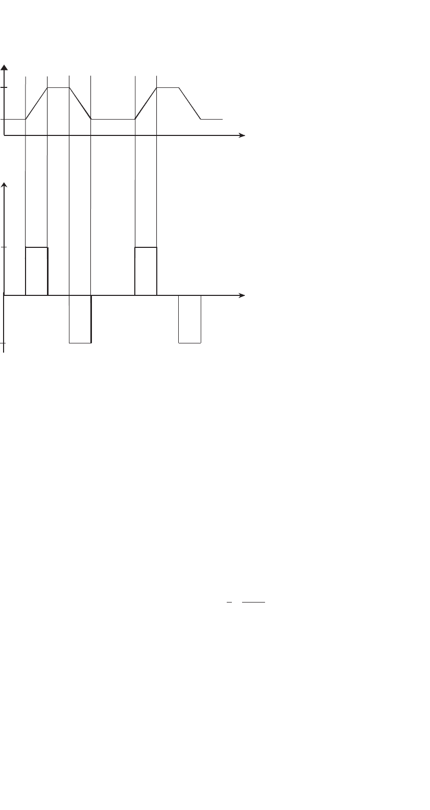
Hence, the ideal waveform for the production of motoring
torque would be a square wave pulse of current (with magni-
tude equal to the maximum possible supply current) flowing
only during the increasing inductance period (Fig. 33.104).
This current waveform is illustrated in Fig. 33.104b. However,
in practice this type of current waveform is difficult to produce
in a motor phase. This is because the motor phase current is
supplied from a finite dc voltage source, and thus inductance
of the stator phase winding would delay the rise and fall of
current at the pulse edges. Instead, a more practical current
waveform is normally used as is illustrated in Fig. 33.104c.
922 M. F. Rahman et al.
(b)
(a)
L(θ)
i(θ)
i(θ)
V (θ)
ψ(θ)
V
s
−V
s
(c)
(θ)
(θ)
(d)
θ
on
θ
on
θ
off
θ
off
θ
q
θ
q
(θ)
(θ)
(θ)
θ
on
θ
off
θ
q
(e)
hysteresis
band
FIGURE 33.104 (a) Linear phase inductance variation; (b) ideal square
wave phase current; (c) chopping-mode phase current; (d) chopping-
mode phase voltage; and (e) flux linkage waveform corresponding to
chopping-mode current.
It can be seen that in this waveform, the ideal square wave-
form is closely approximated by the use of hysteresis current
control. At higher speeds, hysteresis current control can no
longer be used and a current waveform similar to that shown
in Fig. 33.104b is seen in the phase winding. These two types
of practical current waveforms, which approximate the ideal
square pulse waveform (a) at low to medium speeds and (b) at
high speeds, will be discussed next.
33.9.5.1 Low to Medium-speed Approximation to
Square-pulse Current Waveform
At low to medium motor speeds, the ideal square-pulse cur-
rent waveform is approximated in the practical motor drive
using hysteresis current control, as is shown in Fig. 33.104c.
The hysteresis method of controlling the current is termed the
chopping-mode control method in SR motor drives. During the
time of conduction (between the turn-on and turn-off angles),
the current is maintained within the hysteresis band by the
switching off and on of the phase voltage by the inverter when
the phase current reaches the maximum and minimum hys-
teresis band. An example of the voltage waveform used for the
hysteresis current control is shown Fig. 33.104d, where a con-
stant inverter dc supply voltage of magnitude V
s
is used. It can
be seen that the switching frequency of the voltage waveform
decreases as the angle increases. This is due to the fact that the
phase inductance is linearly increasing with angle, which has
the effect of increasing the current rise and fall time within the
hysteresis band.
In the chopping-mode control method, the turn-on region
is defined as the angle between the turn-on angle θ
on
and
the turn-off angle θ
off
, and is chosen to occur during the
rising inductance region for motoring torque. In the prac-
tical chopping current waveform, the current turn-on angle
θ
on
is placed somewhat before the rising-inductance region.
This is to ensure that the current can quickly rise to the
maximum level in the minimum-inductance region before
the rising- inductance, or torque-producing, region. Similarly
the turn-off angle θ
off
is placed a little before the maximum-
inductance region so that the current has time to decay before
the negative-torque, or decreasing-inductance, region. The
angle at which the current decays to zero after turn-off is
labeled as θ
q
in Fig. 33.104c.
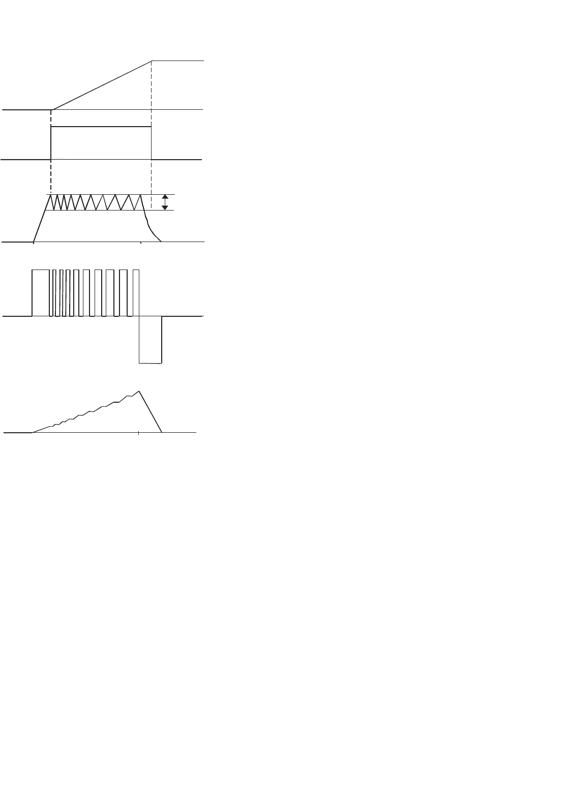
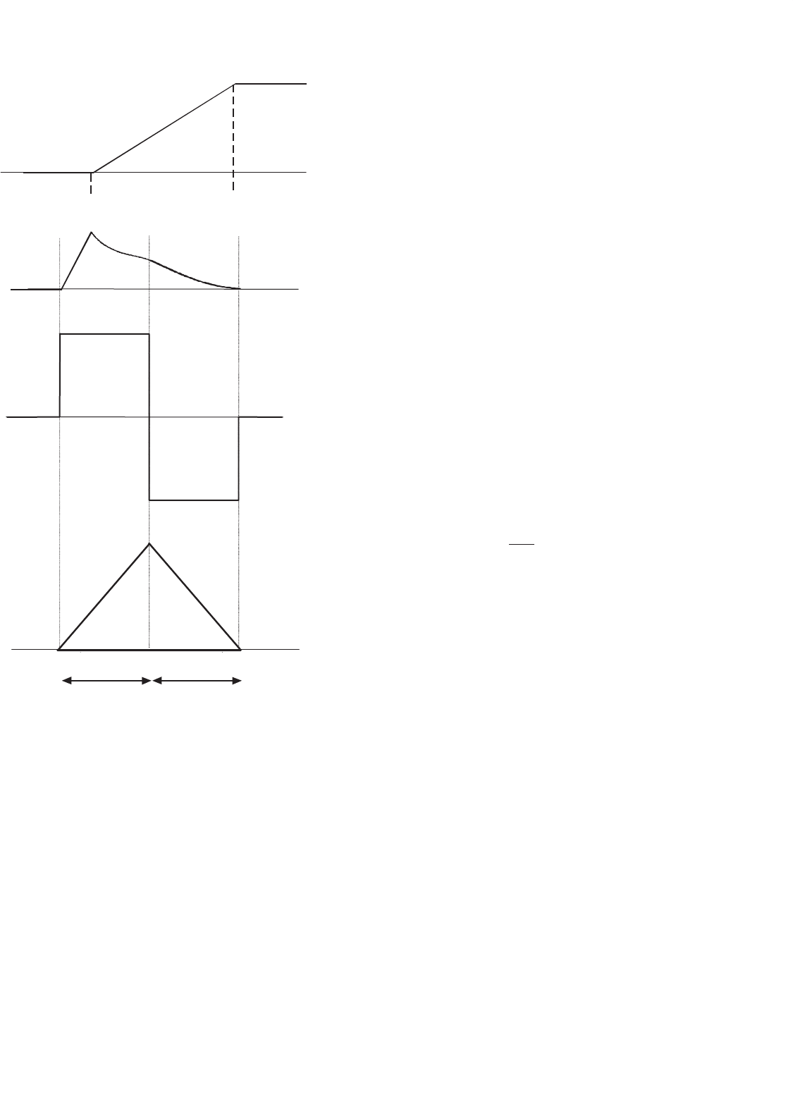
33.9.5.2 High-speed Approximation to Square-pulse
Current Waveform
The chopping-mode of operation cannot be used at higher
speeds, as at these speeds the hysteresis band current level will
not be reached. This is because at high speeds, the back-emf of
the motor becomes equal to or larger than the voltage supply
in the rising-inductance region (Fig. 33.105), which limits the
increase of the motor phase current. In addition, the rise time
of the current will correspond to an ever-increasing angle as
the speed is increased. Eventually, at high speeds, the rise-
time angle will be so large that the turn-off angle θ
off
will be
reached before the hysteresis current level has been exceeded.
Thus, at high speeds, the current is switched on and off only
once per cycle. In SR motor drive control, this is called the
single-pulse mode of operation. An example of the single-pulse
mode current is illustrated in Fig. 33.105b.
In the single-pulse mode of operation, the inverter power
switches turn-on at rotor angle θ
on
, which places the dc volt-
age supply V
s
across the phase winding, as is shown for the
example single-pulse voltage waveform in Fig. 33.105c.
As for the chopping-mode case, in order to maximize
torque, θ
on
must usually be located prior to the rising-
inductance region. This is so that, while the inductance is low,
the current has a chance to rise rapidly to a substantial value
before the torque-producing region begins and the motor
33 Motor Drives 923
(d)
θ
c
θ
r
ψ(θ)
(b)
i(θ)
(θ)
θ
on
θ
on
θ
off
θ
q
(θ)
θ
off
θ
q
θ
on
(θ)
θ
off
θ
q
(a)
L(θ)
(θ)
V
s
V(θ)
(c)
−V
s
FIGURE 33.105 (a) Linear phase inductance variation; (b) single-pulse
mode phase current; (c) single-pulse mode phase voltage, and (d) flux
linkage waveform corresponding to single-pulse mode current.
back-emf increases. At rotor angle θ
off
, the power switches are
turned off, and the phase will have a negative voltage (typically
−V
s
) thrown across it. The current will then decay until it
becomes zero at rotor angle θ
q
.
33.9.6 Operating Theory of the SR Motor (II):
Magnetic Saturation and Nonlinear Model
In the linear model described earlier, it was assumed that
the inductance of a phase winding is independent of current.
However, in a real SR motor, significant saturation of the mag-
netic circuit normally occurs as the phase current increases,
and thus the phase inductance is related to both the phase
current level and position. Because of the magnetic saturation
effect, the actual phase inductances at a given rotor position
can be reduced significantly compared to the inductance given
by linear magnetization characteristics. In addition, the effect
of magnetic saturation becomes larger as the motor current
level increases.
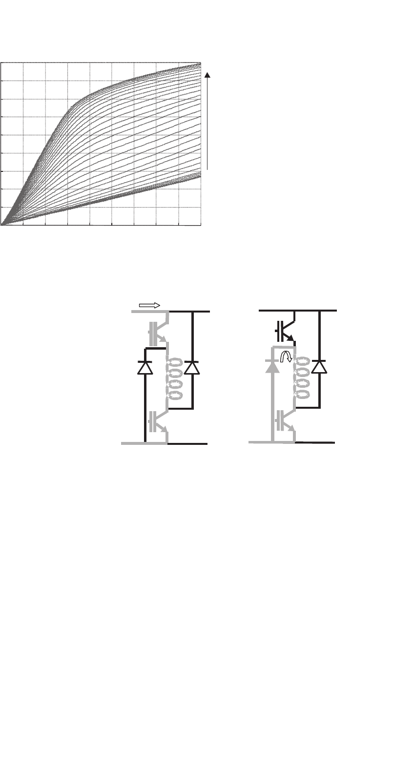
The effects of saturation in an SR motor can be observed in a
plot of its magnetization curves. This shows the relationship of
flux linkage vs current, at rotor positions varying between the
fully aligned and unaligned angles. A typical set of SR motor
magnetization curves is shown in Fig. 33.106, where it can be
seen that there is a nonlinear relationship between the flux
linkage and current for each curve.
Due to the magnetic saturation effect discussed earlier, the
instantaneous torque Eq. (33.96) which was derived assuming
linear conditions, will not be generally valid for calculating
the torque in SR motors. Therefore, for accurate calculations,
the torque must take into account the dependence of phase
inductance with current and position.
If one considers the phase-inductance saturation, the
expression for instantaneous torque production of an SR
motor phase can be written as
T =
∂W
∂θ
i=constant
(33.97)
where the coenergy W
is defined as
W
=
i
0
di (33.98)
33.9.7 Control Parameters of the SR Motor
A variety of performance characteristics can be obtained in the
SR motor by controlling various parameters. These parameters
include the chopping-mode control hysteresis level at low to
medium- speeds, and the turn-on and turn-off angles θ
on
and
θ
off
at all motor speeds. By controlling these parameters, it is
possible to produce any desired characteristic such as constant
torque, constant power, or some other particular characteristic
in between.
As discussed in Section 33.9.5, two distinct modes of oper-
ation apply in the SR motor depending on the nature of the
current waveform. These modes are the chopping-mode con-
trol, which can be used at low to medium motor speeds, and
single-pulse mode of control, which is used at high speeds.
Both of these modes of operation will be further detailed
hereafter, with an explanation of the corresponding inverter
switching operation.
924 M. F. Rahman et al.
0 2 4 6 8 10 12 14 16 18
0
0.1
0.2
0.3
0.4
0.5
0.6
0.7
0.8
0.9
Current (A)
Flux
Linkage
(Wb)
Rotor
Angle
(degrees)
0
30
FIGURE 33.106 Measured four-phase SR motor magnetization characteristics (each curve represents a constant rotor position).
33.9.7.1 Chopping-mode Control
In the chopping-mode control region, the turn-on and turn-
off angles are controlled together with the current level. As
described in Section 33.9.5, the turn-on angle and turn-off
angle are controlled, so that the current flows during the
rising-inductance, or positive torque-producing, region. This
normally means that the turn-on angle is placed shortly before
the place where the rising-inductance angle begins, and the
turn-off angle is placed shortly before this region ends.
In the chopping mode, the current level is controlled to
remain below the maximum allowable level. This involves
switching the voltage across the phase on and off in such a
manner that the current is maintained between some chosen
upper and lower hysteresis current levels. An example of this
form of current chopping control was shown in Fig. 33.104c.
The actual torque production of the motor in the chop-
ping mode is set by the control turn-on and turn-off angles
and the current hysteresis level. Within the chopping-mode
of operation, two current hysteresis control schemes can be
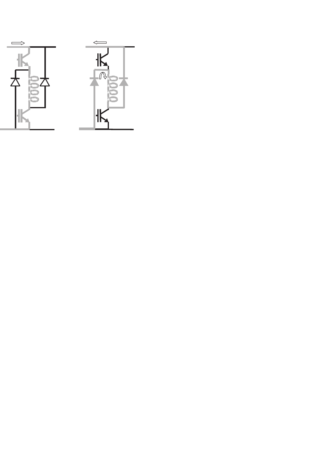
used. These are termed soft and hard chopping. Soft chopping
can only be used in some circuit configurations, such as that
shown in Fig. 33.107. For soft-chopping control, one switch-
ing device remains on during the entire conduction period,
while the other is switched on and off to maintain the desired
current level. This can be seen in Figs. 33.107a and b, where
the two conduction modes during chopping are shown. When
both switches are on, the phase winding receives the full posi-
tive supply, whereas when only one switching device is on, the
phase experiences a zero-voltage freewheeling loop that will
decrease the current.
In the hard-chopping scheme, both devices are switched
simultaneously and have the same switching state at all times.
If both switching devices are turned on, the phase winding
V
dc
T
1
D
2
D
1
T
2
0
i
+V
dc
T
1
D
2
D
1
T
2
0
i
(b)
(a)
FIGURE 33.107 Soft-chopping mode conduction paths: (a) both
devices on: positive voltage applied to motor phase and (b) T1 turned
off: zero voltage freewheeling loop applied to motor phase.
sees the full positive supply. To decrease the current, the full
negative supply is applied by turning both devices off as shown
in Fig. 33.108. In circuit configurations with fewer than two
switches per phase, only hard chopping can be used.
Soft chopping is more advantageous than hard chopping.
This is because of a smaller dc ripple current in the supply,
which can substantially minimize the ripple-current rating of
the dc-link capacitor, as well as lower the hysteresis loss in the
motor. It has also been found that the soft chopping lowers
acoustic noise and electromagnetic radiation.
33.9.7.2 Single-pulse Mode Control
At higher speeds, the back-emf of the SR motor eventually
becomes greater than or equal to the supply voltage during
33 Motor Drives 925
+V
dc
T
1
D
2
D
1
T
2
0
i
+V
dc
T
1
D
2
D
1
T
2
0
i
i
(b)(a)
FIGURE 33.108 Hard-chopping mode conduction paths: (a) both
devices on: positive voltage applied to motor phase and (b) T1 and T2
turned off: negative voltage applied to motor phase.
the rising-inductance region. This means that even if a phase
is excited, the current in the motor phase will not increase
in the rising-inductance region. Therefore, at higher speeds,
the turn-on angle must be placed before the beginning of
the increasing inductance region, so that the phase current
will have an adequate time to increase before the back-emf
becomes high.
In addition, the time available for the current to rise after
turn-on becomes less and less as the speed of the motor
increases. This is due to the fact that the available conduc-
tion time is lower for constant switching angles as the speed of
rotation increases. This can be seen by considering that speed
is the time rate of change of angle. Thus, as the speed increases,
there will be a point when the current level never rises to the
chopping level. At this point, the single-pulse mode of oper-
ation will come into effect and the current will decrease or
remain constant throughout the increasing-inductance zone.
An example of a single-pulse mode current waveform was seen
in Fig. 33.105b.
As the current is not commutated in the single-pulse mode,
the control in this mode consists only of controlling the on and
off angles. The turn-on angle θ
on
can be placed at some point
in advance of the rising-inductance region where the phase
inductance is low, so that the current can increase at a faster
rate before the increasing-inductance region. The angle can be
advanced up until maximum allowable current occurs at the
peak of the waveform (this may even mean switching on in
the previous decreasing-inductance zone). The actual control
turn-on and turn-off angles for the single-pulse mode, for a
given load torque and speed, can be determined by simulating
the motor equations.
The speed at which a changeover between single-pulse and
chopping-mode occurs is called the base speed. Base speed is
defined as the highest speed at which the chopping mode can
be maintained at the rated voltage and with fixed on and
off angles. Below the base speed, the current increases dur-
ing the rising-inductance region, unless it is maintained at the
maximum or a lower level by chopping.
Therefore, it can be seen that at lower speeds that are below
the base speed, the motor is controlled using chopping-mode
control, whereas at speeds above the base speed, the single
pulse mode of control is used. In both the control modes,
the control turn-on and turn-off angles are chosen so that the
motor provides the required load torque.
33.9.8 Position Sensing
It can be seen from the preceding discussion that to control
the SR motor satisfactorily, the motor phases are excited at the
rotor angles determined by the control method. It is therefore
essential to have knowledge of the rotor position. Furthermore,
the rotor-angle information must be accurate and have high
resolution to allow implementation of the more sophisticated
nonlinear control schemes that can minimize torque ripple
and optimize the motor performance.
This means that the performance of an SR drive depends on
the accurate position sensing. The efficiency of the drive and
its torque output can be greatly decreased by the inaccurate
position sensing, and the corresponding inaccurate excitation
angles. It has been demonstrated that at high motor speeds, an
error of only 1
◦
may decrease the torque production by almost
8% of the maximum torque output.
Traditionally, the rotor-position information has been mea-
sured using some form of mechanical angle transducer or
encoder. The position-sensing requirements are in fact similar
to those for brushless PM motors. However, although position
sensing is required for the motor operation, the position-
measurement sensors are often undesirable. The disadvantages
of the electromechanical sensors include the following:
(a) The position sensors have a tendency to be unreliable
because of environmental factors such as dust, high
temperature, humidity, and vibration.
(b) The cost of the sensors rises with the position resolu-
tion. Hence, if high-performance control is required,
an expensive high-resolution encoder needs to be
employed.
(c) There is an additional manufacturing expense and
inconvenience due to the sensor installation on the
motor shaft. In addition, consideration must be given
to maintenance of the motor because of the mechan-
ical mounting of the sensors, which also adds to the
design time and cost.
(d) Mechanical position sensors entail extra electrical
connections to the motor. This increases the quan-
tity of electrical wiring between the motor and the
motor drive. This wire normally needs to be shielded