Power electronic handbook
Подождите немного. Документ загружается.

906 M. F. Rahman et al.
Z
C
(s)
G
A
(s)
(Power
converter
+ motor)
G
L
(s)
(Load)
H
T
(s)
(Sensor)
H
F
(s)
(Filter)
− T
Lm
(s)
w
T
Controller
+
−
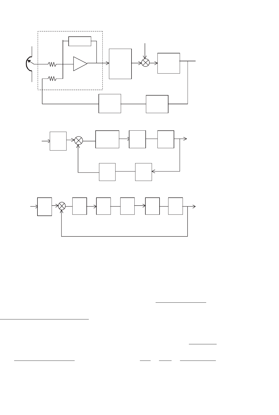
FIGURE 33.75 Block diagram of a speed-control system.
1/R
f
.
Z
C
(s)
R
f
/R
i
+
−
G
A
(s)
G
L
(s)
H
f
(s)
H
T
(s)
E
i
(s)
w
FIGURE 33.76 Simplified representation of Fig. 33.75.
G
C
(s)
R
f
/R
i
G
A
(s) G
L
(s) H
f
(s)H
T
(s)
E
i
(s)
+
−
FIGURE 33.77 Further simplified representation of Fig. 33.75.
The preceding system can be simplified to that shown in
Fig. 33.76, and further to that in Fig. 33.77.
In general, if the individual control blocks are approximated
as first-order systems and are mutually decoupled, meaning
that each block operates in a frequency band that is far outside
the frequency bands of all other blocks, then the foregoing
systems can be represented by a transfer function of the form
G
1
(s) =
K
(
1 +sT
1
)(
1 +sT
2
)(
1 +sT
3
)(
1 +sT
4
)
···
(33.80)
When T
3
and T
4
are much smaller time constants than T
1
and T
2
, the preceding may be approximated by
G
1
(s) ≈
K
(
1 +sT
1
)(
1 +sT
2
)(
1 +sT
s
)
(33.81)
where T
s
= T
3
+T
4
+···etc. A dc-motor speed-control system
with current and speed sensors falls in this category. For such
a system there exist two dominant time constants (poles).
For such a system, a proportional plus integral controller is
of the form
G
c
(s) =
(
1 +sτ
1
)(
1 +sτ
2
)
sτ
0
(
1 +sτ
F1
)(
1 +sτ
F2
)
(33.82)
One optimization criterion (Kessler’s) stipulates that τ
1
≈
T
1
, τ
2
≈ T
2
, and τ
o
≈ 2KT
s
. With this stipulation, the
transfer function of the complete system is given by
G(s) = G
1
(s)G
c
(s) =
1
2sT
s
(
1 +T
s
)
(33.83)
and
V (s)
V
i
(s)
=
G
1 +G
=
1
1 +2sT
s
+2s
2
T
s
(33.84)
33 Motor Drives 907
1
v(t)
t
4.7T
s
0.043
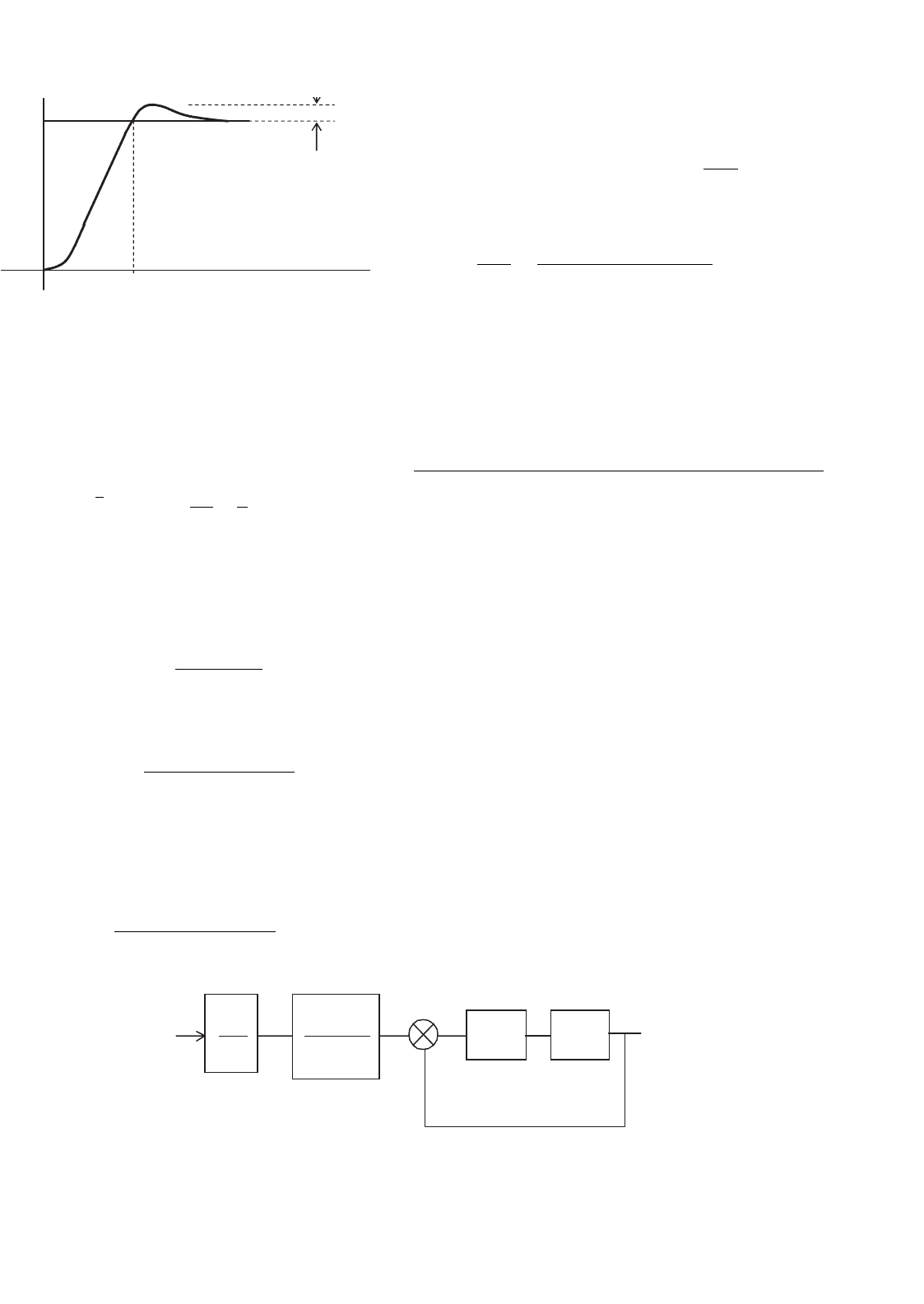
FIGURE 33.78 Response of the optimized system of Fig. 33.75.
Note that the two filter time constants τ
F1
and τ
F2
are
included in G
c
(s) for the sake of its realizability. These can
be relegated to frequencies far higher than the range of inter-
est and can be ignored for further analysis of the system. For
an unit step input of V
i
, the output V is given by
v(t ) = 1 −
√
2 e
−1/2T
s
sin
t
2T
s
+
π
4
for t ≥ 0. (33.85)
A typical output is sketched Fig. 33.78.
If the transfer function G
1
(s) has one dominant time con-
stant T
1
(s), as for the field current control of a dc motor, a
suitable controller is the form
G
c
(s) =
(
1 +sT
1
)
sτ
0
(
1 +sT
F
)
(33.86)
In some cases, the transfer function G
1
(s) is of the form
G
1
(s) =
K
sT
1
(
1 +sT
2
)(
1 +sT
s
)
(33.87)
where T
s
is the sum of a number of short time constants,
associated with sensors, switching frequency, and so on. The
current controller of the dc motor with back-emf has such a
characteristic. A suitable PI controller for this system is
G
c
(s) =
(
1 +sτ
1
)(
1 +sτ
2
)
sτ
0
(
1 +sτ
F1
)(
1 +sτ
F2
)
(33.88)
V
i
1 + 4sT
s
R
f
R
i
G
c
(s) G
1
(s)
+
−
V
1
FIGURE 33.79 Block diagram representation of a typical current controller.
For this system, Kessler’s optimization criterion stipulates
that
τ
1
= 4T
s
, τ
2
= T
2
, and τ
0
=
8KT
s
T
1
The transfer function of the complete system is then
V (s)
V
i
(s)
=
1 +4sT
s
1 +4sT
s
+8s
2
T
2
s
+8s
3
T
3
s
(33.89)
The peak overshoot of this system to a unit step unit is usu-
ally unacceptable, as indicated by the response of Fig. 33.79.
This overshoot is usually reduced by inserting a first-order fil-
ter in the reference circuit. The filter network and the responses
are given in Fig. 33.80.
33.8 Stepper Motor Drives
33.8.1 Introduction
A stepper motor is a positioning device that increments its
shaft position in direct proportion to the number of current
pulses supplied to its windings. A digital positioning system
without any position or speed feedback is thus easily imple-
mented at a much lower cost than with the other types of
motors, simply by delivering a counted number of switch-
ing signals to the motor. Typically, a 200 steps-per-revolution
stepper motor with 5% stepping accuracy will be equivalent
to a dc motor with a 12-bit (or 4000 counts/rev) encoder
plus the closed-loop speed and position controllers for obtain-
ing similar positioning resolution. This advantage, however, is
obtained at a cost of increased complexity of the drive circuits.
A disadvantage of the motor is perhaps its inability to reach
an absolute position, since the final position reached is only
relative to its arbitrary initial position. Nevertheless, the true
digital nature of this motor makes it a very suitable candi-
date for digital positioning systems in many manufacturing,
automation, and indexing systems.
The working principle of stepper motors is based on the
tendency of the rotor to align with the position where the
stator flux becomes maximum (i.e. seeking of the minimum-
reluctance position, also called the detent position). The rotor
908 M. F. Rahman et al.
1
v
Time, msec
0.43
0.08
Without input filter
With input filter
3.1T
s
7.6T
s
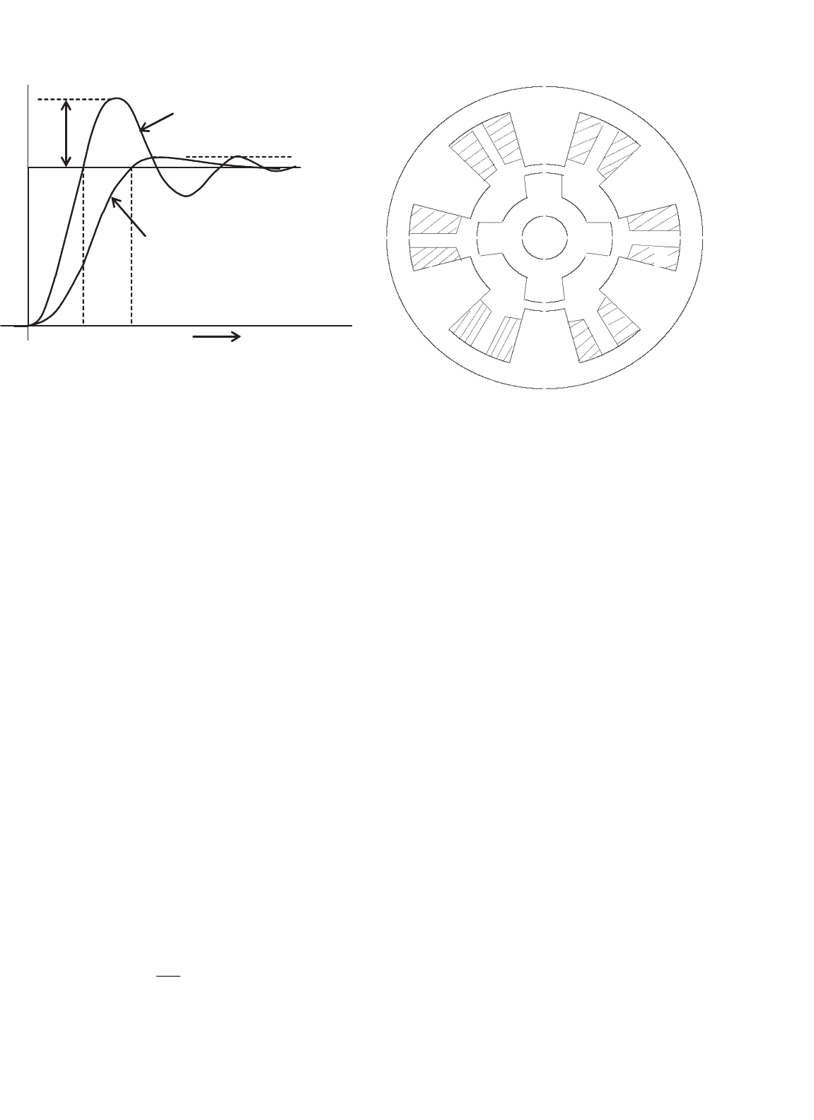
FIGURE 33.80 Optimized response of the system of Fig. 33.80.
and the stator are both toothed structures, and the stator nor-
mally has more than two windings to step the rotor in the
desired direction when they are energized in certain combina-
tions with current. Some motors additionally have permanent
magnets embedded in the rotor that accentuate an already
existing, zero-excitation detent torque. These motors hold
their positions even when the stator excitations are removed
completely, a feature desirable for some applications.
In addition to the point-to-point stepping action, these
motors can also be operated at high slewing speed, simply by
increasing the pulsing rate of phase currents. Since the motor
is inherently a synchronous actuator, the pulsing rate has to
be increased and decreased properly, so that the rotor may
follow it. At the end of a complete run, the motor always
stops at the desired incremental position or angle without any
accumulated error. The only error that may be encountered
is mainly due to the machining accuracy of the teeth in the
stator and rotor. This error is of the order of about 5% of one
step position/angle and it is nonaccumulative.
33.8.2 Motor Types and Characteristics
33.8.2.1 Single-stack Variable-reluctance
Stepper Motor
Single-stack motors are normally of the variable-reluctance
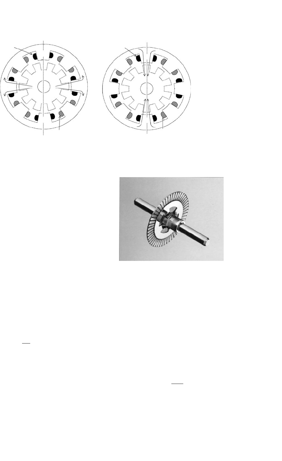
type with no excitation in the rotor. The cross section of a
three-phase motor with two stator poles/phase and four rotor
poles are indicated in Fig. 33.81. The motor can be stepped
clock or anticlockwise by energizing the phase winding in the
ABCA or ACBA sequence, respectively. The step angle, i.e.
the angle moved by the rotor for each change in excitation
sequence, of the motor is given by
θ
s
=
360
NP
degrees (33.90)
A
A
C
A
B
B
A
C
C
C
B
B
FIGURE 33.81 Cross section of a single-stack variable-reluctance
stepper motor.
where N is the number of phases in the stator and P is the
number of poles in the stator. Single stack motors typically
has larger step angles than other types because of limitations
of space for the windings. The step angle of these motor tend
to be larger than the multistack and hybrid stepper motors.
For each excited winding, the motor develops a torque angle
(T–θ) characteristic as indicated in Fig. 33.82. Note that there
are two equilibrium positions of the rotor, namely, X and Y ,
where the motor develops zero torque.
The position X is referred to as the stable detent position,
around which the rotor develops a restoring torque when dis-
placed. The restoring torque increases as the rotor is moved
from its detent position, becoming a maximum T
max
on either
side of this position. The slope of the T–θ characteristic around
this detent position and the maximum torque, both of which
depend on the level of excitation, indicate how far the rotor
will be displaced under load torque. This means that the level
of excitation also affects the position holding accuracy of the
motor.
The motor may also be excited in the sequence: AB–BC–CA
or AB–CA–BC for forward and reverse stepping, respectively.
The two phases-on scheme develops more torque around the
detent positions at the expense of twice the resistive losses.
Yet another excitation scheme is AB–B–BC–C–CA–A–AB
for forward stepping and AB–A–AC–C–BC–B–AB for reverse
stepping. In this scheme, the step size is halved as opposed to
the full-step size of the previous sequences. Two different levels
of torque is produced for alternate detent positions. However,
the reduced step size and the more damped nature of each step
may outweigh this disadvantage.
33 Motor Drives 909
XYY
−T
max
T
max
q, rad
T, Nm
Stable detent
Unstable detent
dT
dq
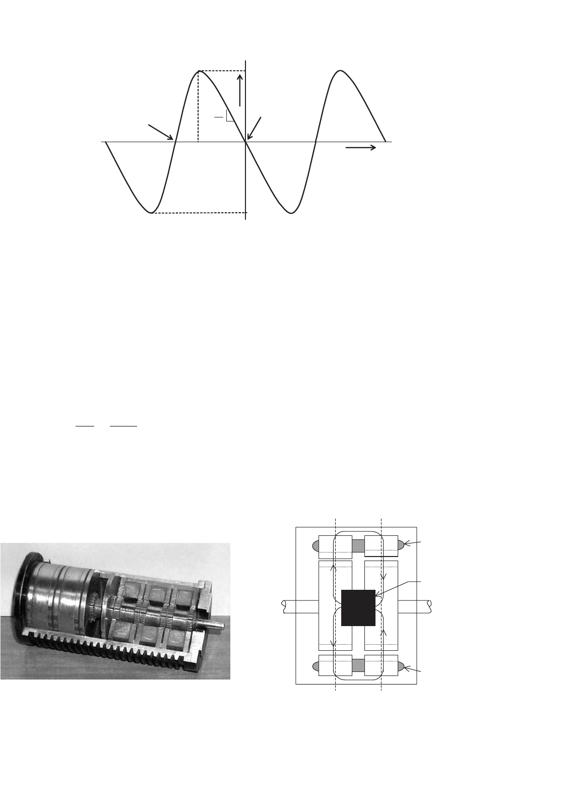
FIGURE 33.82 Static torque characteristic of a stepper motor.
33.8.2.2 Multi Stack Variable-Reluctance
Stepping Motor
In a multi stack variable-reluctance motor, the stator windings
are stacked along the shaft. Each stack section now has the
same number of poles in the stator and the rotor. Normally
each stator stack is staggered with respect to its neighbor by
one/Nth of a pole pitch, where N is the number of stator/rotor
phases or sections. The cut out view of Fig. 33.83 shows some
internal details of a six-phase multi stack motor, in which
each stack has a phase winding between two rings, each with
32 stator and rotor poles. The step size of this motor is
θ
s
=
360
◦
Np
=
360
◦
6 ×32
= 1.875
◦
(33.91)
The excitation sequence of this motor is similar to the ones
mentioned in Section 33.8.2.1, except that more excitation
sequences are available. When a stator winding is energized,
the rotor poles of that section tend to align with those defined
FIGURE 33.83 Cut out view of a six-phase, multi stack, variable-
reluctance stepper motor. Courtesy: Pratt Hydraulics, UK.
by the stator excitation. The stator and rotor teeth in the
other sections are not aligned. By changing the combination
of excited phases to the next in sequence, the rotor is made to
move by one step angle.
33.8.2.3 Hybrid Stepping Motor
A hybrid stepper motor has an axially oriented permanent
magnet sandwiched between two sections of the stator and
rotor, as indicated in Fig. 33.84. The magnetic flux distributes
radially through the two stator and rotor sections, both of
which are toothed, and axially through the back iron of the
stator and the shaft. The stator has two phase windings, each
of which creates alternate polarities of magnetic poles in both
sections of the stator. Stator windings are excited with bipolar
Rotor magnet
Stator and
Rotor sections
YX
Stator winding
Stator winding
FIGURE 33.84 Axial section of the hybrid motor.
910 M. F. Rahman et al.
Phase A
Phase B
X
8
3
2
6
4
7
1
5
(
a
)
2
3
4
8
7
6
Phase A
Phase B
Y
5
1
(
b
)
FIGURE 33.85 Cross section of the hybrid motor: (a) section X and (b) section Y.
currents, as opposed to the unipolar currents in the variable-
reluctance motors of the two preceding sections. The magnetic
flux produced by the stator windings is circumferential in each
stator and rotor section, but also crosses the airgap radially.
It does not, however, pass through the rotor magnet. The two
rotor sections are offset by half its tooth pitch.
The rotor magnet causes to the stator and rotor teeth to set-
tle at the minimum reluctance position with a modest amount
of detent torque to keep the rotor in position, when the
stator windings are not energized. The rotor magnetic flux
distributes outward through stator poles 3 and 7 in section X
and inward through poles 1 and 5 in section Y , as shown
in Figs. 33.85a and b. When the stator windings A and B
(indicated as dark and faint shaded, respectively) are energized
with positive and negative currents, respectively, the resulting
stator flux also distributes through these same poles, so that
the rotor then develops a much higher detent torque (T–θ)
characteristic. The motor can be stepped forward or backward
by energizing windings in sequence A
¯
B −AB −
¯
AB −
¯
A
¯
B or
A
¯
B−
¯
A
¯
B−
¯
AB−A
¯
B respectively, where the over bar indicates
the polarity of currents in phases A and B.
The stepping angle of a hybrid stepper motor is given by
θ
s
=
90
◦
P
(33.92)
where P is the number of rotor poles.
33.8.2.4 Permanent-magnet Stepping Motor
Permanent-magnet stepper motors have alternate polarities of
permanent magnets on the rotor surface while the rotor iron,
if it is used, has no teeth. In one type of construction, the
rotor has no iron, and the stator consists of two windings that
FIGURE 33.86 Rotor of a PM stepper motor. Courtesy: Escap Motors.
setup alternate poles when energized, just as in the case of
the hybrid motor. The rotor consists of permanent magnets,
alternately polarized, attached to the surface of a nonmagnetic
disk, as shown in Fig. 33.86. The stator and rotor fluxes cross
the airgap, one on either side of the disk, axially.
33.8.3 Mechanism of Torque Production
33.8.3.1 Variable-reluctance Motor
If it is assumed that the current in the excited wind-
ing remains constant, the production of static torque of a
variable-reluctance motor around a detent position is given by
T =
dW
m
dθ
(33.93)
This torque expression may also be expressed as in Eq. 33.94,
when it is further assumed that the inductance of the excited
33 Motor Drives 911
FIGURE 33.87 Stator and rotor teeth alignment: (a) aligned position,
θ = X and (b) unaligned position, θ = Y .
winding at any given position remains constant for all
currents.
T =
1
2
i
2
dL
dθ
(33.94)
The developed torque is due to the variation of induc-
tance (or reluctance) with position. Note that the direction
of current has no bearing on the developed torque. When
the stator and rotor poles are perfectly aligned, as indicated in
Fig. 33.87a, the inductance L changes little with a small change
in θ. The developed torque is thus very small around this posi-
tion, corresponding to the position X in Fig. 33.82. When
the stator and rotor teeth are unaligned, as in Fig. 33.87b,
L changes more significantly with θ, and the restoring torque
becomes much larger. As θ increases, dL/dθ goes through a
maximum, producing T
max
. It should be noted that around a
stable detent, L reduces as θ increases, so that the slope of the
T–θ characteristic is negative at the origin. Beyond the position
where T
max
is developed, L increases as a result of the next set
of rotor teeth coming under the stator teeth. This explains the
drop in T
max
and the positive slope of the T–θ characteris-
tic in the region between where T
max
is developed and Y in
Fig. 33.82.
If stepper motors are operated in magnetically linear region
where L remains constant with the current for a given angu-
lar position, the developed torque per unit volume is small.
Because of this, steppers motors are normally driven far
into saturation. Equation (33.94) then does not represent the
torque characteristic adequately.
For a saturated stepper motor, the calculation of the T–θ
characteristic for any given current involves complex com-
putation of stored energy, or coenergy, for each position of
the rotor. This requires the magnetization characteristics of
the motor for different levels of stator currents and rotor posi-
tions to be known. Reference [33] may be consulted for further
reading on this.
33.8.3.2 Hybrid and PM Motors
In hybrid stepper motors, most of the developed torque is con-
tributed by the variable-reluctance principle explained earlier.
The rest is developed by the rotor magnet in striving to
find the minimum-reluctance position. It should be noted
that the alternate polarities of the magnetic poles created by
each winding may be reversed by the direction of its current.
Consequently, the polarity of the winding currents also deter-
mines the direction in which the developed torque increases
positively around a detent position.
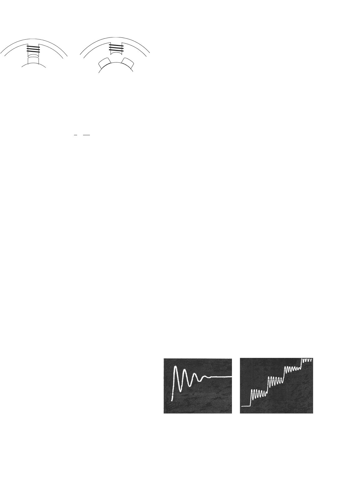
33.8.4 Single- and Multi-step Responses
When the rotor is at a detent position and phase currents are
changed to a new value, the detent position is moved and
the rotor proceeds towards it and settles down at the new
detent position. The movement of the rotor is influenced by
the shape of the T–θ characteristic and the load friction. The
rotor stepping is normally quite under-damped. The final posi-
tioning error is also determined largely by the load torque. For
instance, if the T–θ characteristic is assumed to be a sinusoidal
function of θ, the error in stepping is given by Eq. (33.95),
where T
max
is the peak of the T–θ characteristic and T
L
is the
load friction torque.
θ
e
=
sin
−1
(
T
L
/T
max
)
(33.95)
However, this error does not accumulate as further stepping
is performed. If the phase currents are switched in succession,
the rotor makes multiple steps. Typical single and multi step
responses are as indicated in Fig. 33.88.
The maximum rate at which the rotor can be moved
depends on several factors. The rise and fall times of the wind-
ing currents, which are largely determined by the electrical
parameters of the windings and the type of drive circuits used,
and the combined inertia and friction parameters of the motor
and load are important factors.
The discrete signals to step the motor in the forward or
reverse direction are translated into current-switching sig-
nals for the drive circuits. This translator is a simple logical
operation that is embedded in most of the integrated circuits
available for driving stepper motors.
In many applications, the stepper motor is operated at far
higher speeds than which it can start/stop from. The perfor-
mance of a stepper motor at high speed is normally given
in terms of its pull-out torque-speed (T–ω) characteristic.
(a) (b)
FIGURE 33.88 Typical step responses of a stepper motor: (a) single step
response and (b) multi step response.
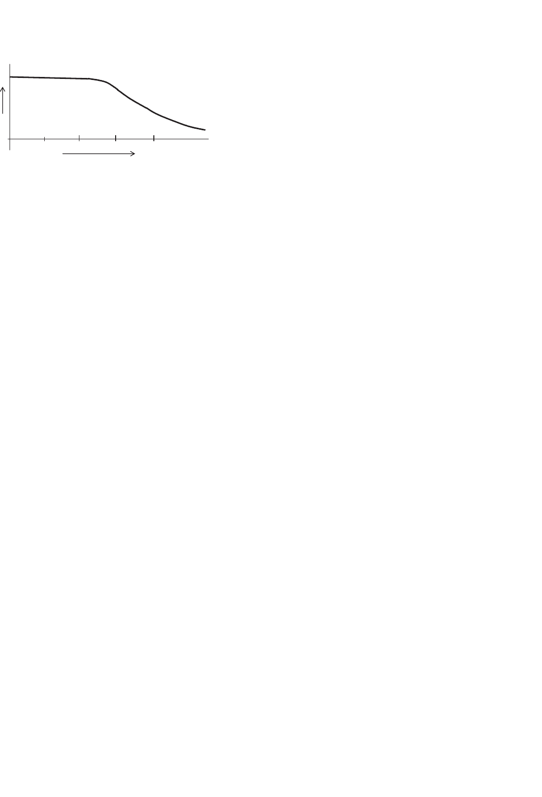
912 M. F. Rahman et al.
Ste
pp
in
g
rate in ste
p
s/sec
Pull-out
torque, Nm
10
10,0001000 100
FIGURE 33.89 Typical pull-out torque characteristic of a stepper
motor.
This characteristic indicates the maximum average torque, the
motor may develop while stepping continuously at a given
rate. This torque is also largely determined by the parameters
of the motor and its drive circuits. Figure 33.89 indicates the
typical shape of the pull-out T–ω characteristic of a stepper
motor drive.
At low speed, the pull-out torque is roughly equal to the
average value of the positive half-cycle of the T–θ waveforms of
Fig. 33.82. At high speed, the finite but fixed rise and fall times
of the currents and the back-emf of the winding reduces the
extent to which the windings are energized during each switch-
ing period. Consequently, the pull-out torque of the motors
falls as the stepping rate (speed) increases.
For operation at high speed, the stepping rate is gradually
increased and decreased from one speed to another. With-
out careful acceleration and deceleration to and from a high
speed, the motor will not be able to follow the stepping com-
mands and will lose its synchronism with the stepping pulses
or winding excitations. The acceleration and deceleration rates
of a stepper motor are also determined largely by the pull-out
torque characteristic.
Stepper motors are known to suffer from mechanically
induced resonance and consequent mis-stepping when its
switching rate falls within certain bands, which are largely
determined by the way the developed torque varies with
time, as the motor steps. Careful selection of stepping rate
is normally employed to overcome the problem. Some shaft-
mounted external damping measures may also be used when
the stepping rate needs to be continuously varied, such as in
the case of machine-tool profile following.
33.8.5 Drive Circuits
Two types of drive circuits are in general use for stepper
motors. The unipolar drive is suitable for variable-reluctance
stepper motors, for which the developed torque is deter-
mined by the level of current, not its polarity. For hybrid
and permanent-magnet motors, the direction of current is also
important, so that the bipolar drive circuits are more suitable.
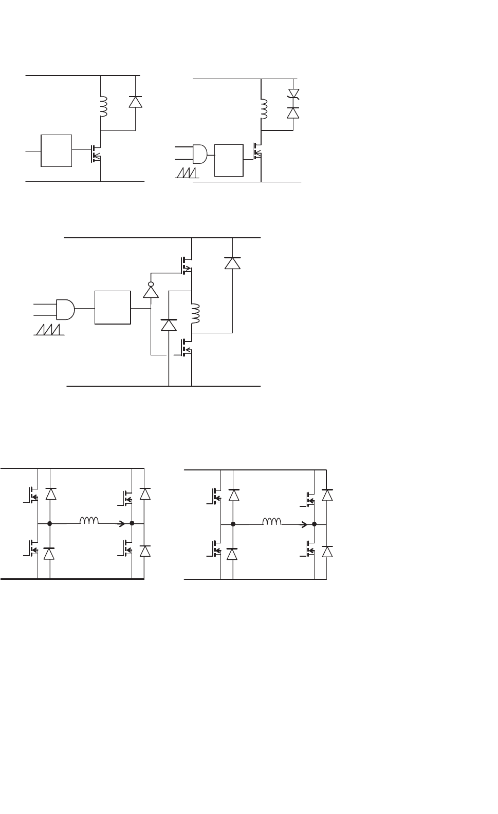
33.8.5.1 Unipolar Drive Circuits
In its simplest form, the unipolar drive circuits, one for
each winding, are as indicated in Fig. 33.90. The transistor
(MOSFET) is turned on to energize the winding, with a current
that is limited either by the winding resistance or by hysteresis
or PWM current controllers. The freewheeling diode allows
the winding current a circulating path when the transistor is
turned off.
The drive circuit of Fig. 33.90a is a basic one. A better drive
circuit is shown in Fig. 33.90b, which includes a zener diode
in the freewheeling path. A pulse-width modulator is also
included in the gate driving circuit. The pulse-width mod-
ulator allows a higher dc supply voltage (typically 5–10 times
the voltage for the resistance-limited drive) to be used, thereby
reducing the rise time of current at switch-on by 5–10 times.
The zener diode allows a fast fall time for the current when the
transistor is turned off by dissipating the trapped energy of the
winding at switch-off faster. Yet another scheme is shown in
Fig. 33.90c which allows the trapped energy of the winding at
switch-off to be returned to the dc source when the transistor
is turned off, rather than being dissipated in the winding or
the freewheeling circuits. This circuit is by far the most effi-
cient, and at the same time gives the fastest possible rise and
fall times for the winding currents.
33.8.5.2 Bipolar Drive Circuits
The bipolar drive allows the motor windings to be driven
with bidirectional currents. The four-transistor bridge drive
circuit of Fig. 33.91, one for each winding, is the most popu-
lar. The circuit can cater to the required rise and fall times of
the winding by properly selecting the dc supply voltage V
dc
,
the pulse-width modulator, and the current controller gains.
Some hybrid and PM motors come with four windings, two
for each phase. These may be connected in series or parallel,
depending on the torque characteristics desired. In any case,
only two drive circuits of the type indicated in Fig. 33.91 are
required.
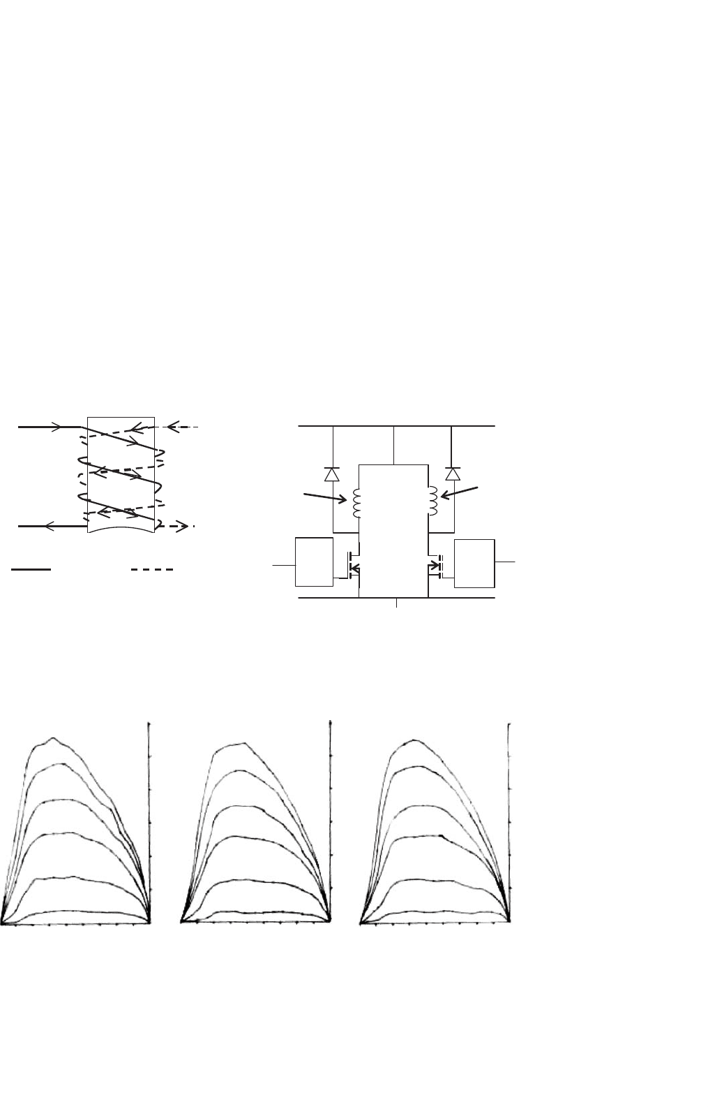
33.8.5.3 Drive Circuits for Bifilar Wound Motors
Hybrid stepping motors may also come with bifilar windings,
which allow the simpler unipolar drive circuits to be used.
These motors have two tightly coupled windings for each
phase. Figure 33.92 illustrates two bifilar windings on stator
pole and their unipolar drives. The two windings on each pole
have opposite sense, so that the magnetic polarity is reversed by
simply switching the other winding. Since only unidirectional
current is involved, the unipolar drive circuits of Fig. 33.90a
or b may be used at a considerable savings in terms of the drive
circuits. This benefit is, however, derived at the cost of extra
winding space, and hence larger volume, for the same torque.
33 Motor Drives 913
V
dc
GND
A
Winding
A
T
A1
D
A1
D
A2
T
A2
Gate
Drive
Circuit
(c)
V
dc
GND
A
Winding A
T
A
D
A
Gate
Drive
Circuit
(a)
V
dc
GND
A
Winding A
T
A
D
A
Gate
Drive
Circuit
Z
DA
(b)
FIGURE 33.90 Three commonly used unipolar drive circuits: (a) the basic unipolar drive; (b) unipolar drive with PWM current limiting and zener
diode turn-off; and (c) unipolar drive with regenerative turn-off.
D
2
T
2
T
4
T
3
T
1
D
3
D
4
D
1
V
dc
Winding A
GND
D
2
T
2
T
4
T
3
T
1
D
3
D
4
D
1
V
dc
Winding B
GND
FIGURE 33.91 Bipolar drive circuit (gate-drive circuits omitted).
33.8.6 Micro Stepping
The drive sequences mentioned in Section 33.8.2 normally
switch rated current through the motor windings. These pro-
duce regular step angles. The half-stepping operation also uses
rated motor currents. Halving of the step angle is arranged
mainly through the selection of the windings switched.
In micro stepping, the regular step angle of the motor is
subdivided further by a factor, typically from 10 to 100, by
energizing the windings partially, with combinations of cur-
rents ranging from zero to full rated value in more than one
windings simultaneously. This does not lead to any sacrifice of
the developed torque, since the phase currents are so selected
914 M. F. Rahman et al.
that the peak of total torque contributed by two partially ener-
gized windings is not lower than the peak detent torque T
max
obtained in regular stepping.
The idea behind micro stepping is readily understood when
it is considered that by increasing the current in phase A of a
two-phase hybrid in 10 equal steps to full value and decreasing
the current in phase B in a similar manner, the motor step size
may be divided by a factor of 10. If the closed-loop current
controllers are added to the two drive circuits of Fig. 33.91
and distinct current references are obtained from a reference
generator, a complete micro stepping drive is realized.
In micro stepping, the two current references must have
values such that the motor does the following:
1. Develops the same T
max
for every combination of
winding currents.
2. Develops the same torque slope, i.e. dt/dθ at every
micro stepping detent position.
V
dc
Gate
Drive
Circuit
Gate
Drive
Circuit
GND
A
m+
A
mz−
A
BF−
A
BF+
Main
Winding
(phase A)
Bifilar
Winding
(phase A)
(a) (b)
A
m+
A
m−
A
BF+
Main
winding
Bifilar
winding
A
BF−
FIGURE 33.92 Drive circuits for one phase of a bifilar-wound motor: (a) bifilar pole windings and (b) drive circuits.
T, Nm
1
T, Nm
6
5
4
3
2
T, Nm
Phase A Phase B Phase C
6A
5A
4A
3A
2A
1A
6A
5A
4A
3A
2A
1A
6A
5A
4A
3A
2A
1A
98 7 6 5 4 3 2 1
1
2
3
4
5
6
0 9876543210 9876543210
0
0
1
6
5
4
3
2
0
FIGURE 33.93 T–θ characteristics of a three-phase variable-reluctance motor.
3. Dissipates no more than the rated power loss (I
2
R) for
every combination of winding currents.
The preceding conditions are necessary if the motor is
to retain its static accuracy, maximum torque, and power
dissipation characteristics.
The static torque characteristics (Fig. 33.92) of stepper
motors are close to, but not exactly, sinusoidal functions of
angle θ. The required current references for all windings of a
stepper motor, including the variable-reluctance motor of
three or more phases, can easily be calculated from the data of
the T–θ characteristics of the motor for each phase for various
currents and rotor positions. A typical set of T–θ data for a
three-phase variable-reluctance motor is shown in Fig. 33.93.
The application of the three conditions mentioned earlier leads
to an unique set of current references for each phase of the
motor for each micro step. Figure 33.94 shows the current
references for this motor for micro stepping.
33 Motor Drives 915
FIGURE 33.94 Micro stepping current references for the VR motor of
Fig. 33.93. Stepping rate: 28,800 steps/s., I = 6 A (maximum).
In multi stepping operation, these micro stepping current
references have to be issued to the current controllers for each
phase, at a rate determined by the commanded stepping rate.
Care has to be taken in designing the phase-current con-
trollers so that the actual winding currents match the current
references in both single and multi stepping operation up to
the maximum stepping rate desired. Since the current refer-
ences are time varying, high-bandwidth current controllers are
normally required to cover the desired speed range.
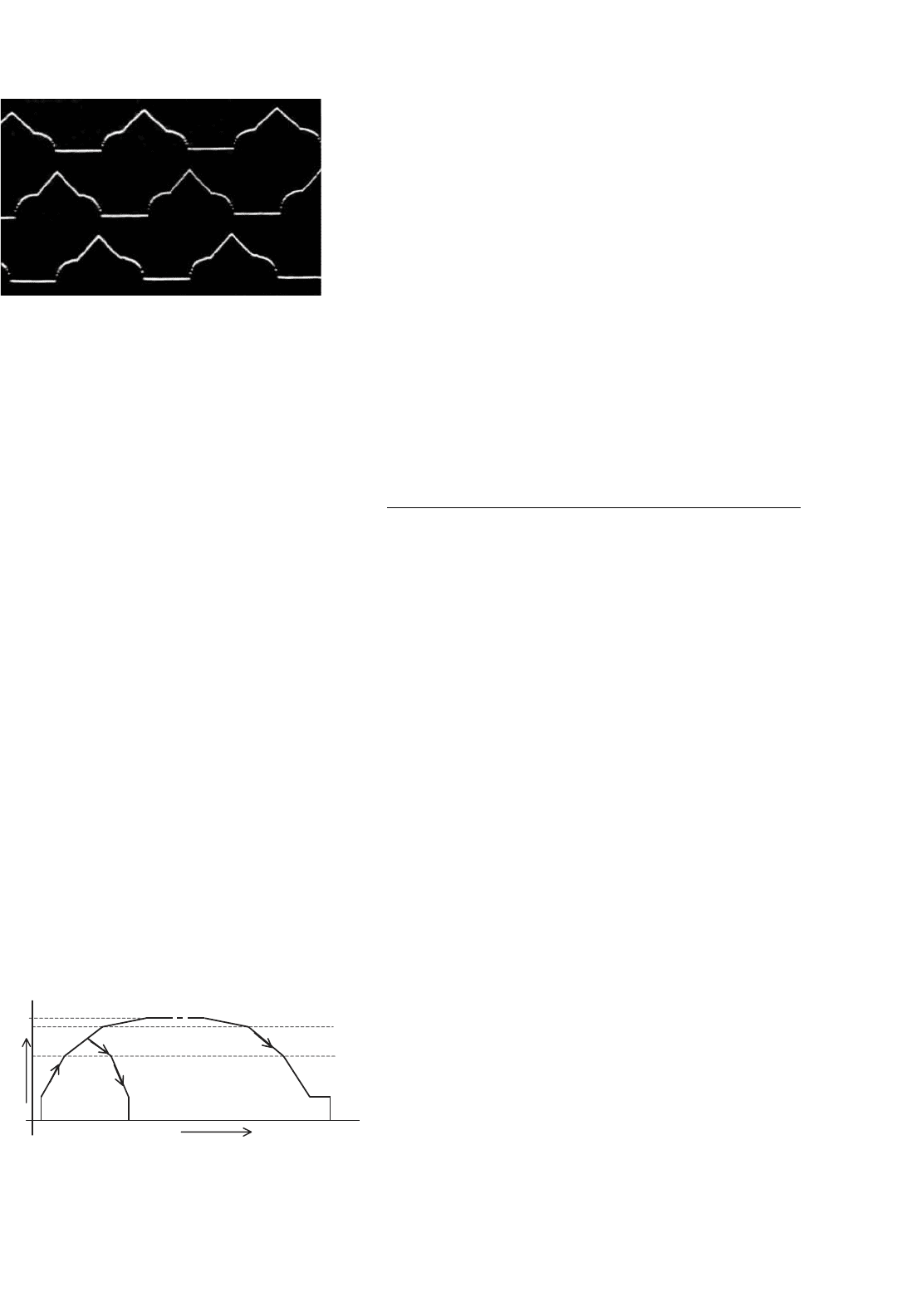
33.8.7 Open-loop Acceleration–Deceleration
Profiles
As mentioned in Section 33.8.4, many applications require the
stepper motors to be driven far above the stepping rates to and
from which the motor can start and stop abruptly without
losing or gaining any step. This calls for carefully designed
acceleration–deceleration profiles that the stepping pulse rate
must not exceed.
The number of steps the motor is to be stepped and its
direction are normally under the control of the motion con-
troller. Once this reference is known, a digital timer/counter
circuit can be used in the controller to progressively adjust
the time between the stepping pulses such that a prescribed
acceleration–deceleration profile, as indicated in Fig. 33.95, is
followed. The timer/counter and the pulsing sequence con-
troller (the translator) need to be managed in realtime to
execute the motion-control task at hand.
Stepping
rate
Time, tt = 0
f
max
,
ksteps/sec
FIGURE 33.95 Typical acceleration–deceleration profiles.
The fastest acceleration–deceleration profile, a stepper
motor is capable of is largely determined by its pull-out (T–ω)
characteristic, which in turn is determined by the motor wind-
ing parameters and the drive circuit. An optimized stepping
profile to and from the top speed may have a number of
segments as indicated in Fig. 33.95. These profiles are easily
computed from the pull-out (T–ω) characteristic by integrat-
ing the dynamic torque balance equation of the drive. For
a large positioning angle, the entire profile, including some
constant-speed running at the top speed, may be used. For
short positioning angles, only part of the profile may be tra-
versed. In general, a single segment acceleration–deceleration
profile is used in commercial stepper motor controllers, so as
to avoid a great deal of realtime number crunching by the
profile controller.
The overall stepper motor controller thus consists of the
blocks depicted in Fig. 33.96.
33.9 Switched-reluctance Motor Drives
33.9.1 Introduction
The switched-reluctance (SR) motor is a doubly salient elec-
tric machine with salient-poles on both the stator and rotor.
The machine is operated by switching current pulses to each
stator winding on and off in a continuous switching sequence.
The rotor poles have no excitation. Figure 33.97 shows the
physical topology of a typical SR motor. The diagram illus-
trates a motor with eight salient stator poles (numbered A1 to
D2) and six salient rotor poles (numbered 1 to 6). Although
many combinations of the number of stator and rotor poles
are possible, this particular type has found widespread use.
The phase windings on the stator of the SR motor consist
of concentrated windings wrapped around the stator poles.
In the conventional arrangement, each stator pole winding is
connected with that of the diametrically opposite pole to form
a stator phase. In Fig. 33.97, the connected stator pole pairs
are indicated by the same prefix letter.
The general principle of operation of the SR motor is the
same as all types of reluctance machines, i.e. the stator and
the rotor poles seek the minimum-reluctance position, so
that the stator excited flux becomes maximum. Hence, when
current flows in an SR motor stator phase and produces a
magnetic field, the nearest rotor pole will tend to position
itself with the direction of the developed magnetic field. This
position, which is termed the aligned position, is reached when
the rotor pole center axis is aligned with the stator pole cen-
ter axis (assuming symmetrical poles). The aligned position
also corresponds to the position of minimum reluctance, and
hence the position of maximum inductance.
It should be noted that the unaligned position is defined
as the position when the inter-pole axis, or the axis of the
center of the inter-polar space in the rotor, is aligned with a