Power electronic handbook
Подождите немного. Документ загружается.

896 M. F. Rahman et al.
When starting, or at a low speed, the current in a winding
is limited only by the very low resistance and, for the machine
above by Ohm’s law, I = E/R would result in more than
2000 amperes.
The most common requirement for a steady current in
the windings is to provide a steady torque. There is always
a back-emf generated in the windings whenever the motor is
rotating, which is proportional to speed and subtracts from
the applied voltage. Thus currents cannot be determined just
by terminal voltage. The winding does however have induc-
tance. Whenever the copper conductors are put in coils in an
iron structure, particularly if there are low reluctance mag-
netic paths with only small airgaps, the creation of quite large
inductances cannot be avoided. These are used to very good
effect.
The nature of inductance is that when a voltage is applied to
an inductor, instantaneous current does not result, rather the
current begins to increase and ramps up in a quite controlled
fashion. If the voltage across the inductor is reversed the cur-
rent does not immediately reverse, rather it ramps down, will
go through zero and reverses if the reversed voltage is left there
long enough. However, if the voltage is alternated by switch-
ing rapidly, as can be done with power electronics, the current
can be controlled to ramp-up and ramp-down either side of
a desired current, staying within any determined tolerance of
that desired current.
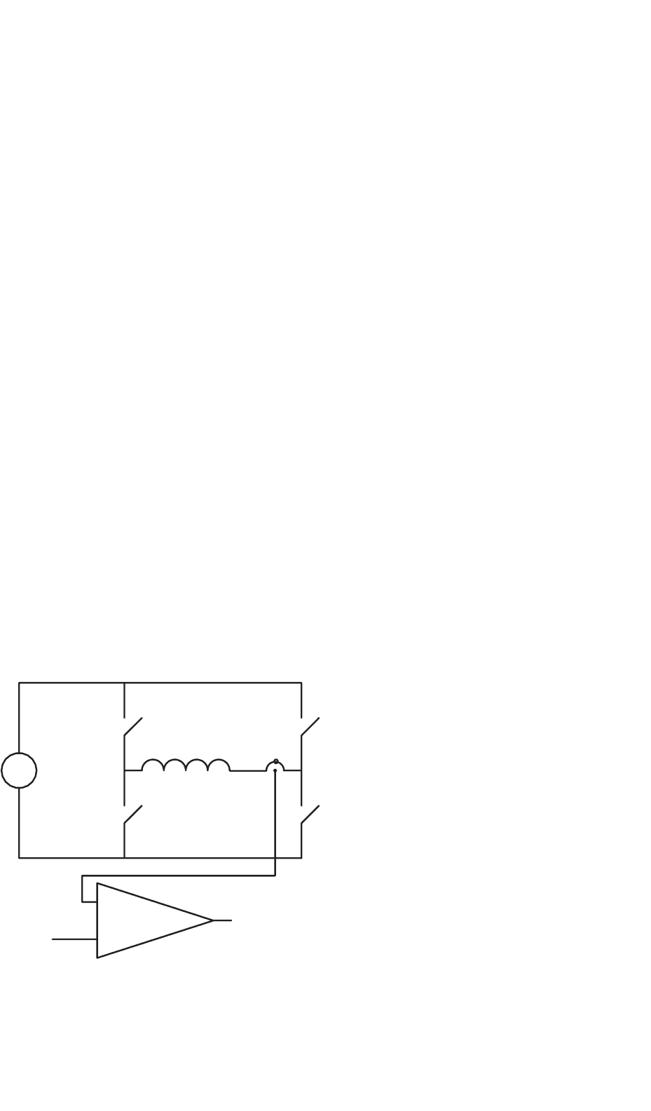
Figure 33.63 looks very much like the simple “H” bridge
commutation circuit, but is performing a very different func-
tion. It is controlling the current amplitude to stay within a
desired band. If S1 and S4 are turned on then the current will
begin to increase from left to right in the winding. The current
sensor in the circuit detects when the current reaches a value
of half the hysteresis band of the comparator above the desired
Desired Current (torque),
eg ±5V represents maximum
positive or negative torque.
+
a
a′
S1
S2
S3
S4
−
V
in
Comparator
with hysteresis, eg
±100 mV
+
−
PWM logic signal output.
Turns on S1 and S4 if high (current below reference),
or S2 and S3 if low (current above reference)
Current sensor,
voltage output
proportional
to current
FIGURE 33.63 Hysteresis band current control using pulse-width modulation (PWM).
current level and initiates turn-off of S1 and S4 and turn-on
of S2 and S3. (If they were all turned off at once, the inductive
nature of the circuit would produce very high voltages which
would cause arcing in mechanical switches, or breakdown and
failure of semiconductor switches, see later.) The current then
begins to reduce. It reduces a small amount, down to half the
hysteresis band of the comparator below the desired current
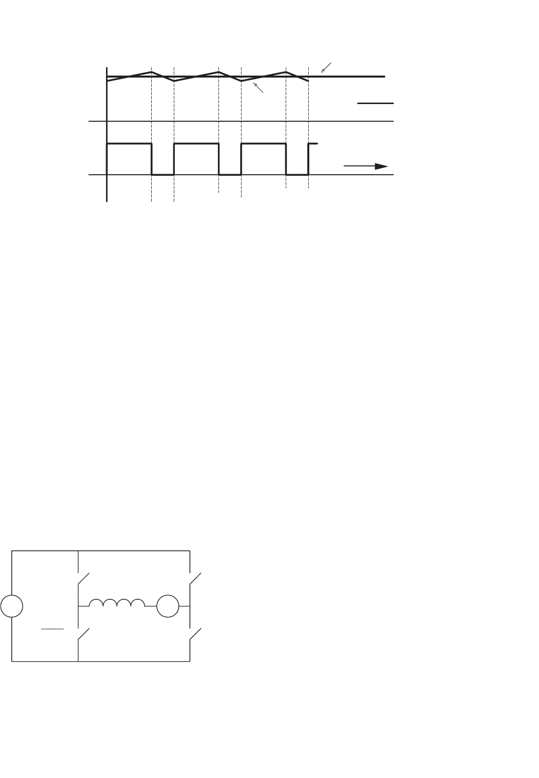
level and then the switches reverse again. Thus a desired cur-
rent level is achieved, with an arbitrarily small triangular ripple
superimposed, as shown in Fig. 33.64.
The general process of controlling by switching a voltage
fully on or fully off at high speed is called pulse width mod-
ulation (PWM) and the specific method of current control
achieved above with PWM, is called hysteresis band current
control (HBCC).
Of course to keep this current ripple small, the switching
may need to be very fast, but with the modern semicon-
ductor switches there is no great problem up to 100 kHz for
small machines and typically above 15 kHz for acoustic noise
reasons, for machines rated up to several hundred kilowatts.
A perceived “drawback” of HBCC is that the switching fre-
quency is determined by the circuit inductance, the width of
hysteresis band, the back-emf, and the applied voltage, ranging
very widely in normal operation. It is not difficult, but it is a
little more complicated, to use a fixed frequency, and a linear
analog of the current error to modify the pulse width of the
PWM signal.
33.6.3.1 Switching Losses
There is a practical limit to how often semiconductor switches
can be operated. At every change of state, if the switch is carry-
ing current as it is opened, then as the voltage rises across the
33 Motor Drives 897
Current
PWM
Logic signal
output
Time
Desired current
Actual current
1
0
FIGURE 33.64 Hysteresis band current control and PWM waveforms.
switch and the current through it falls, there is a short pulse
of power dissipated in the switch. Similarly, as the switch is
closed, the voltage will take some time to fall and the current
will take some time to rise, again producing a pulse of power
dissipation. This loss is called switching loss. Fairly obviously
it will represent a power loss proportional to the switching
frequency and so the switching frequency is generally set as
low as it can be without impinging on the effective operation
of the circuit. “Effective operation” might well include criteria
for acoustic noise and levels of vibration.
33.6.3.2 High Efficiency Method of Managing the
Switching in the H Bridge
A very common way to control the current with the smallest
number of switching transitions is to combine HBCC with,
for example, alternating only S1 and S2 in Fig. 33.65 leaving
S4 on all the time, on the understanding that there will be a
back-emf in the winding and the current can still be increased
or decreased as desired.
Thus when the motor is rotating and the back-emf is
somewhere between zero and the rail voltage, alternating two
switches rather than four will still allow current control in the
coil, using for example HBCC, exactly as before.
+
a
a′
S1
S2
−
+−
Ea
Vin
On
Off
S3
S4
PWM
PWM
FIGURE 33.65 H-bridge switching with one switch steadily on and a
back-emf.
This is a very common control scheme and will need some
extra logic to reverse the direction of rotation of the motor, by
either turning S4 off and S3 on continuously, or by swapping
the control signals to the left and right “legs.” For full-servo
operation normal H-bridge switching can be used and the logic
is slightly different, but not significantly more complicated.
However, following the discussion above, the switching losses
will be higher.
33.6.3.3 Combining Commutation and PWM Current
Control
The real break-through is that one set of six switches can be
used for both PWM and commutation. That is the clever part
and also the confusing part when one first tries to understand
what is going on.
Thus, in a controller there are two control loops. The first
is an inner current loop switching at, for example, 15 kHz to
control carefully and exactly the current in two of the coils.
Then at a much lower rate, for example at 50 times per second
at 3000 rpm, the two coils doing the work are changed accord-
ing to Table 33.2, controlled by an outer commutation loop,
using information from the Hall effect shaft position sensors.
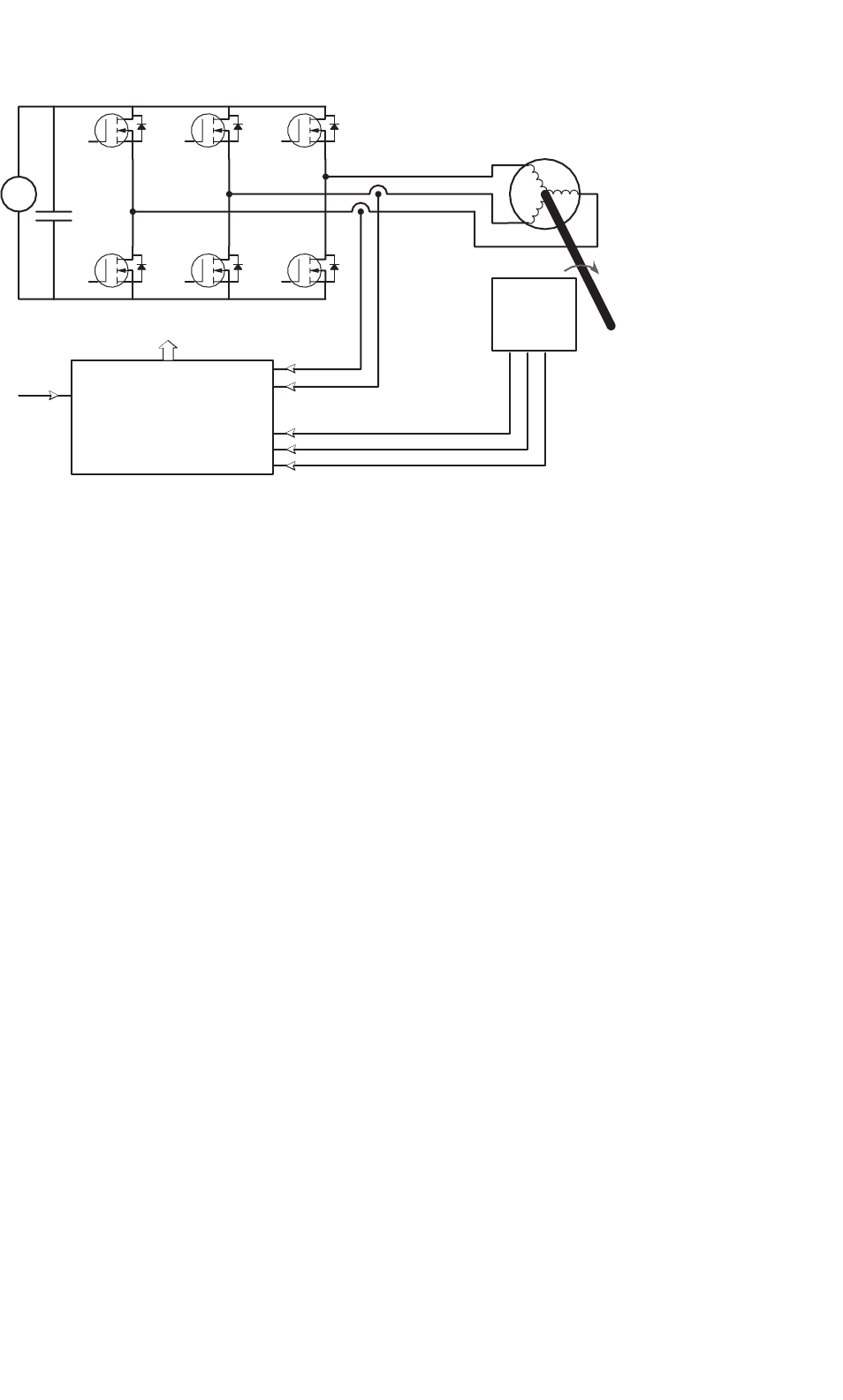
A complete controller is shown in the block diagram form
in Fig. 33.66. Various aspects of this block diagram will now
be examined and explained in detail.
33.6.3.3.1 Hardware Details – Semiconductor Switches The
three most likely semiconductor switches for a six step
controller are the bipolar junction transistor (BJT), the
metal-oxide silicon field effect transistor (MOSFET) and the
insulated gate bipolar transistor (IGBT). Older controllers
used BJTs, however contemporary controllers tend to use
MOSFETs for lower voltages and powers and IGBTs for higher
voltages and powers. Both of these devices are controlled by a
gate signal and will turn-on when the voltage of the gate above
898 M. F. Rahman et al.
+
−
G1
G2 G4
G5
G6
C
in
G3
Hall effect
shaft
position
sensors
Analog and digital
signal processing
Gate drives G1 to G6
Desired current
(torque) command
Current
sensors
S1
S2
S3
S4
S5
S6
FIGURE 33.66 A complete controller showing the two feedback paths, one for the position sensors and one for the current sensors.
the source or emitter is greater than a threshold, which is typ-
ically about 5 V. Use of about 10 V is common. The devices
are thus off when the gate voltage below the threshold. Sys-
tems typically use zero volts for the off state. The controller of
Fig. 33.66 shows MOSFETs used for the six switches.
The trick is that the voltage at terminal a, also S1’s source, is
either ground or the positive potential of the battery, depend-
ing on which switches are on. Driving S2, S4, and S6 is easy
since the MOSFET sources are all at the potential of the neg-
ative rail and the lower gate drive signals are referred to this
rail.
There is a range of dedicated integrated circuits which can
drive the switches S1, S3, and S5, and which use a “charge
pump” principle to generate the drive signal and the drive
power internally, all related to the MOSFET source potential.
Various approaches to this technical challenge of providing a
floating gate drive are commonly discussed under the generic
heading of “high side drives.”
For the most sophisticated drives, transformer coupling is
used to provide a tiny power supply especially for the isolated
gate drive and send the control signals either through an opto-
coupler or a separate transformer coupling. The high-side
drive problems here are exactly the same as those encountered
in the traditional buck converter, or in drives for induction
motors and PMSMs.
33.6.3.3.2 Dead Time and Flyback Diodes Two issues have
been mentioned above that must be addressed when using
high-speed electronic switches in inductive circuits.
The first, in Section 33.6.2 “Electronic Commutation,” was
that care should be taken to ensure that the upper and lower
switches in the same “leg,” (e.g. S1 and S2) are never turned
on at the same time. If the controller attempts to turn one
off and the other on at the same instant and switch turn-off
is slower than turn-on (as it is with BJTs and IGBTs), then
a short circuit will result for a brief time. The bus capaci-
tor is usually very large to provide ripple current (see later)
and usually of very high quality being fabricated especially for
power-electronic applications, and can easily provide thou-
sands of amperes for a few microseconds, which is enough to
destroy the semiconductor switches.
The second issue, discussed in Section 33.6.3 “Current/
Torque control,” is that one cannot turn-off both switches in
a leg at the same time, even for a few nanoseconds, since the
voltages resulting from attempting to interrupt current in an
inductor will cause avalanche breakdown and failure of the
semiconductors. This sounds like quite a dilemma.
There is actually a very simple and effective solution. At
any transition, the control circuitry ensures that the active
switches are all turned off before any switch is turned on,
usually for a few microseconds. This is known as “dead time”
and its provision is an essential part of most of the dedicated
integrated circuits in use. Then a “flyback”/“freewheel” diode
is put in anti-parallel with each semiconductor switch and this
provides the current path during dead time. These diodes are
shown in Fig. 33.66.
The diode has a little more loss than the switch, since the
diode forward drop is more than the switch drop. This is sig-
nificant in a low voltage controller. However, as stated above,
for a low voltage controller, MOSFETs are the device of choice.
They have a lesser known property, that when gated on, they
can carry current in both directions. Intriguingly the “on” state
resistance is lower in reverse than in the forward direction!

33 Motor Drives 899
PWM
logic signal
output
1
0
I up logic
signal
I down logic
signal
Dead time
Time
FIGURE 33.67 Dead time introduced into the PWM logic signal, for switch drive.
Thus for low voltage controllers, when the switch forward drop
represents a significant contribution to losses, the MOSFET is
turned on after dead time for both the current directions. Thus
the higher loss in the diode is only for a few microseconds.
It is not difficult to produce from the PWM signal an “I up”
logic signal which is used to cause the current to increase and
an “I down” logic signal used to decrease it, with the timing as
shown in Fig. 33.67. The function can be executed in sequential
logic, or with the simple analog timing circuits.
A. Semiconductor Detail
In MOSFETs and most IGBTs, there is a diode already within
the device; it is unavoidable and results from the fabrication
processes. In modern power semiconductors, this intrinsic
diode is optimized to be a good switching diode. The seri-
ous designer, however, will check the specifications for reverse
recovery of this diode, since in highly optimized controller
designs, reverse recovery losses in the intrinsic diode can be
significant and are very difficult to control. In low voltage
controllers, you can put a Schottky diode in parallel with the
intrinsic body diode. The Schottky diode, with its lower for-
ward voltage drop will tend to take the current and has no
reverse recovery problems, but the current must commutate
to it from the semiconductor die and the inductance of the
connections is critical.
B. The Smoothing Capacitor on the Input to the Controller
This is a substantial capacitor, often very expensive, (it is
shown in Fig. 33.66 as C in) and its design is quite chal-
lenging. The issue of smoothing is quite serious. If there are
high-frequency or sudden current changes in the leads from
the dc supply to the controller, they will radiate electromag-
netic energy. Good design will limit the length of conductors
in which the current is changing rapidly. Thus, a very large
capacitor is placed physically as close to the positive bus of
the switches as possible, aiming to have a steady current in
the longer conductors from the dc supply, up to the capacitor.
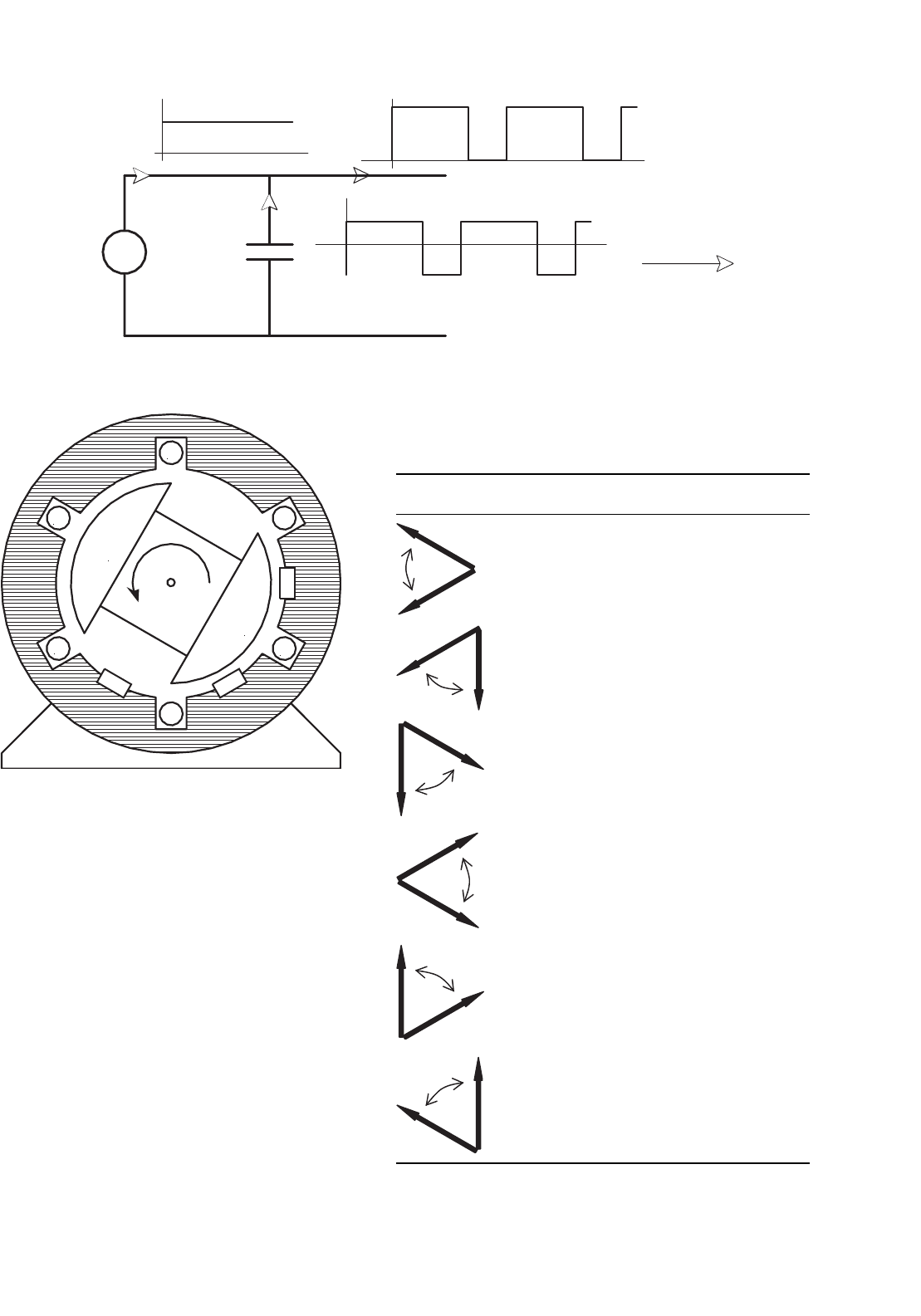
When the motor is running at, say, half speed and providing
large torques, a very high level of ripple current is carried by
this capacitor. Kirchhoff’s current law (KCL) must be applied
at node A, as shown in Fig. 33.68. Good capacitors have a rip-
ple current maximum buried away in their specification sheet.
It turns out that in general, the size of the capacitor in a given
design has very little to do with how much voltage ripple you
can tolerate at the bus, but rather is determined by the ability
to carry the ripple current without the capacitor heating up
and failing. It has been known that the small electrolytics in
prototype controllers mysteriously explode. On searching, it
is found that they are in parallel with the main capacitor and
quite close to it, so they carry a lot of ripple current, then heat
up and explode!
33.6.4 The Signal Processing for Producing
Switch Drive Signals from Hall Effect
Sensors and Current Sensors
33.6.4.1 Operation of the Hall Sensors
The flux density directly under a magnet pole can be anywhere
from 500 to 800 millitesla with Nd–Fe–B magnets. Hall effect
(HE) sensors with a digital output, called Hall effect switches,
change state at very close to zero flux density. Thus, they will
change state when the north and south pole are equidistant
900 M. F. Rahman et al.
I controller
I capacitor
I supply
A
Voltage source
To controller switches
FIGURE 33.68 Kirchhoff’s current law at node A.
a
a′
b
b′
c
c′
N
S
HE1
HE3
HE2
FIGURE 33.69 Possible Hall effect switch positions in a three-phase
machine.
from them, so that for example, in Fig. 33.69, the switch HE1
is just changing state with the rotor as shown.
In practice, a motor designer needs to consider what magne-
tomotive force comes from the current in the windings which
might result in flux which would trip the HE sensor at a slightly
different time. If you follow all the above logic about six step
switching, you will see that you only need the magnet poles to
have a span of a bit more than 120
◦
. Using 180
◦
magnet poles
can add considerably to the cost, as well as having an impact
on such things as cogging torque. Actual designs often add
extra “sense” magnets to cover 180
◦
just at the circumferential
strip where the HE switches are located, adding minimally to
the magnet mass and ensuring good and accurate triggering.
However, if the switches operate as above, then Table 33.3
will result for the HE switches located as shown in Fig. 33.69.
TABLE 33.3 Hall effect switch outputs for rotor positions as shown, HE
switches placed as in Fig. 33.69
When the center of the rotor
north pole is in this sector
HE1 outputs HE2 outputs HE3 outputs
100
110
111
011
001
000

33 Motor Drives 901
33.6.4.2 Sensing the Current in the Motor Windings
Figure 33.66 shows two current sensors. In the most sophisti-
cated systems, there are two current sensors, one in each of the
two motor phases. The current sensing is done at the winding
and isolated with either an HE sensor in a soft ferromagnetic
magnetic core surrounding the conductor (commercial items
are available), or by using a resistive shunt sensor and some
accurate analog signal isolation/coupling through transformers
or opto-couplers. The isolation is necessary since the poten-
tial at points a, b, and c is either the dc bus voltage or zero,
depending on which switches are on, so that any current mea-
sure such as the small voltage across a shunt is superimposed
on these very large voltage changes. This is a very similar prob-
lem to that for the high side gate drives discussed earlier. The
current in the third winding is determined by the algebraic
application of KCL, given the other two readings.
Simple controllers sometimes avoid the complexities of iso-
lated current measurement and instead measure the current
in the return negative supply, for example from the bottom of
the three lower switches to the bottom of the supply smooth-
ing capacitor. This arrangement senses current when an upper
and a lower switch is on, but not when the current is being
carried in flyback diodes or by two lower switches. While it
is inexpensive, it does not provide fully accurate control. The
system works because the current should be decreasing when
a measure is not available, heading towards zero, so switch or
system failure due to over-current should not occur.
33.6.4.3 Management of Current Sensing
The controller must select the right current to increase or
decrease, dependent on rotor position. The following con-
vention is adopted. Positive current provides torque in the
counterclockwise direction and therefore goes into winding a,
b,orc.
All systems are capable of regeneration, which implies that
negative torque can be commanded (without reversing the
direction of rotation) to make the machine operate as a
generator, developing retarding torque.
Thus for the above sequence of sector determinations, refer-
ring back to Table 33.2, the output of current sensors should
be directed to the current controller as shown in Table 33.4.
The addition and negation required can be carried out
with the standard operational-amplifier circuitry. The three
required analog measures are then fed to a three to one ana-
log multiplexer, gated from the HE switch signals suitably
processed in combinational logic. The resulting single analog
output is fed to the current comparator.
33.6.4.4 Distribution of Control Signals
to the Switches
Given that the dead time is introduced elsewhere in sequential
logic, or with timing circuits, it is a simple matter to develop
TABLE 33.4 Current sensors to use as input to the current
controller, for each of the six rotor position sectors
Hall effect switch outputs
(HE1, HE2, HE3)
Monitor current as read by
100 Negative of (sensor a+ sensor b)
110 Negative of (sensor a+ sensor b)
111 Sensor b
011 Sensor b
001 Sensor a
000 Sensor a
TABLE 33.5 Distribution of control signals to the switches using “High
Efficiency Method of Managing the Switching in the H Bridge”
HE states(1,2,3) S1 S2 S3 S4 S5 S6
100 0 0 0 1 I up I down
011 0 1 0 0 I up I down
001 0 1 I up I down 0 0
000 0 0 I up I down 0 1
100 I up I down 0 0 0 1
110 I up I down 0 1 0 0
the combinational logic for directing, or steering, the switching
signals to the right switches. A typical scheme for a specific
controller is shown in Table 33.5.
It is usual also to include some shutdown logic from ded-
icated protection circuits, for example sensing over-current,
over-bus voltage, under voltage for gate drive and over-
temperature both in the motor and in the controller power
stage. For simplicity, this is not shown in the table.
33.6.5 Summary
What is Discussed in the above
The physical principles of the operation of a PMBDCM have
been discussed which lead to the development of the necessary
parts of a power electronic controller. One specific type of
current control, hysteresis band current control was explained
in detail, and one specific type of switch logic pattern was
developed. The exposition has included many of the issues
that can cause difficulties for controller designers if they are
not careful.
What is Not Discussed in the above
Many PMBDCMs have more than one pair of poles. The
arguments above can all be extended to higher pole count
machines, by taking any mention of degrees to be electrical
degrees rather than mechanical degrees. The controller dis-
cussed in detail only manages one direction of rotation. It
is an excellent exercise, and straightforward, but not trivial,
to repeat the above steps, preparing the tables for clock-
wise rotation of the simple machine discussed above. Then,

902 M. F. Rahman et al.
following the discussion in the first part of Section 33.6.3,
Current/Torque Control about H bridge switching, prepare the
logic tables again for full bidirectional control, using the I up
and I down logic signals exactly as above, but applying them to
both “legs” determined by the rotor position. Only one form
of current sensing was discussed in detail. There are many sim-
pler schemes in use which do not have quite the flexibility and
accuracy of the above, but which can suit certain applications.
Similarly, there are other forms of current control such as
the constant-frequency linear method briefly discussed. Shaft
position sensors take many forms. Adherence to the HE sensor
was for simplicity, and to reinforce the magnetic field aspects
of the machine operation.
33.7 Servo Drives
33.7.1 Introduction
Servo drives are motor drives that operate with high dynamic
response. Historically, servo drives have implied motion-
control systems in which sophisticated motor design, drive,
and control techniques have been employed to obtain very
much shorter positioning times than is possible with con-
ventional drive systems. Examples are in machine tool drives,
robotic actuators, computer disk drives, and so on. The power
range for these drives has typically been in the range of a few
kilowatts or less. This range has steadily increased in recent
years as a result of advances in magnetic materials, machine
design, power and signal electronic devices, and sensors.
Apart from the fast positioning times, “high dynamic
response” also means that the drive operates with the follow-
ing:
1. Very smooth torque up to a very low speed,
2. Very high reliability and little maintenance,
3. Immunity from load disturbances.
The last of the foregoing items is brought about by robust
and intelligent control algorithms; the first two items are
brought about by innovative and often costly motor and con-
troller designs. As a result of these, the cost of a servo motor
drive is usually much higher than the equivalent power rated
industrial drives.
The distinctions just mentioned may be easily recognized
by noting, for example, that the drives that bring material to
a mill may not require high performance, but the drives that
take part in shaping, milling, or reducing the material should
have high dynamic response in order to increase throughput
and meet the accuracy requirements of the final product.
33.7.2 Servo Drive Performance Criteria
The performance of a servo drive can be expressed in terms
of a number or factors such as servo bandwidth, accuracy,
percentage regulation, and stiffness. While servo bandwidth
indicates the ability of the drive to track a moving or cyclic
reference, the percentage regulation and stiffness stipulates the
drive’s static holding performance for speed or position, in the
face of disturbances from the load and in the supply condi-
tions. The servo bandwidth, specified as a frequency in Hertz
or rad/sec, is often found from the system frequency response
plot, such as the Bode diagram.
The percentage regulation of a speed-controlled system
often refers to the percentage change in speed from no load
to full load. In a type-zero system, this figure will have a finite
value. Many systems are type zero, albeit with a high gain so
that the regulation is acceptably low. For such systems, the
regulation is often necessary for operational reasons. In some
applications, zero percentage error is required, which calls for
type 1 or integral type control system.
The servo stiffness is similar to the percentage error men-
tioned earlier, but it applies mainly for the position servo. It
specifies the deflection of the load from its reference position,
when full load torque is applied. It is usually the slope of the
deflection versus the applied load torque in rad/Nm around
the reference position.
33.7.3 Servo Motors, Shaft Sensors, and
Coupling
Servo drives use motors which allow the desired goals of high
dynamic response to be achieved. The important parameters/
attributes of a servo motor are:
1. High torque-to-inertia ratio,
2. High torque-to-volume ratio,
3. Low inductance of the motor windings,
4. Low cogging torque at low speed,
5. Efficient heat dissipation,
6. Low coefficient of shaft compliance,
7. Direct-coupled, high-resolution, shaft-mounted sensors
for position and speed.
High torque-to-inertia ratio allows fast acceleration or
deceleration of the drive when motion references are changed.
This is often achieved through innovative low-inertia rotor
design and low inductance in the stator winding. One example
of a dc servo motor is the pancake printed armature dc motor
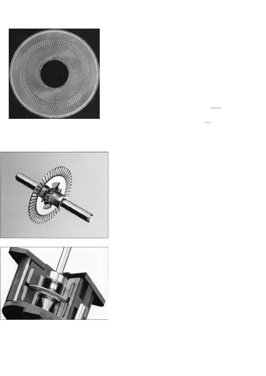
with no iron in the rotor, as indicated in Fig. 33.70. The rotor
is sandwiched between axially mounted stator poles. The com-
mutator is also on the printed armature. Another example is
the disk rotor stepping motor, also without iron in the rotor,
as indicated in Fig. 33.71.
The PM ac synchronous motors with modern high-energy-
density magnets in the rotor, as described in Section 33.6, are
also examples where the motor designer strives to minimize the
rotor inertia. Modern permanent magnets allow the required
airgap flux to be developed with a much reduced volume of
the magnets, consequently reducing the diameter of the rotor.
33 Motor Drives 903
FIGURE 33.70 Pancake armature of a dc servo motor. Courtesy:
Printed Motors Ltd., UK.
FIGURE 33.71 A disk rotor stepping motor with ironless rotor for low
inertia and inductance. Courtesy: Escap Motors.
It is well-known that the moment of inertia of a motor
increases as the fourth power of its outer radius!
Another benefit of the modern permanent-magnet material
is that the motor volume is also reduced. Servo motors often
have to be located in a very confined space, and this reduction
in volume is an important attribute.
The ironless designs mentioned earlier bring other bene-
fits in the form of reduced inductance and cogging torque.
Brushed pancake ironless motors are available with armature
inductance as low as 100 µH.
From Section 33.2.2, the mechanical and electrical time
constants of a brushed dc motor are given by
τ
m
= mechanical time constant =
R
a
J
K
E
K
T
s
and τ
a
= electrical time constant =
L
a
R
a
s.
It is well known that for the highest load acceleration, the
load inertia referred to the motor should be equal to the rotor
inertia. Thus, in a matched system, the total inertia the
motor accelerates is twice its own inertia. In other words, the
motor inertia should also be minimized.
For a good servo motor, the ratio between the mechanical
and the electrical time constants is often of the order of five or
more. This allows the speed and the current-control loops to
be decoupled and noninteracting. The electrical time constant
of a motor determines how quickly the motor current may be
changed and hence how quickly the torque can be changed.
As also mentioned in Section 33.2, drives with a reasonable
dynamic performance should have an inner torque loop. This
torque loop is built around current loops, for the armature for
the brushed dc motor, or for the d- and q-axes currents for
the induction and synchronous motor drives. Having a low
inductance in the winding allows these currents to be followed
dynamically changing current or the torque references with
higher accuracy and bandwidth.
The cogging torque, if appreciable, causes the rotor to have
preferential positions. As a result, the position accuracy of the
motor may suffer. Another problem is the ripple in speed as
the motor is operated at low speed. At high speed, these ripples
due to cogging torque may be filtered out by the motor inertia;
however, the extra loss due to cogging remains. The ironless or
toothless rotor obviously produce very small cogging torque
because of the absence of preferential paths for the airgap flux
to establish through the rotor iron of the brushed dc motor.
The surface-magnet synchronous motor also has this feature.
The interior-magnet motor normally has skewed stator slots
to avoid the production of cogging torque.
Servo motors often operate with frequent start-and-stop
duty, with the fastest allowable acceleration and deceleration
during which the motor current is allowed to reach about
2–3 times the continuously rated current. The increased I
2
R

904 M. F. Rahman et al.
loss in such duty must be dissipated. This calls for adequate
cooling measures to be incorporated in the motor housing.
With such operation, it is sometimes possible to excite the
mechanical resonance due to shaft compliance. This is avoided
through proper arrangement of the shaft position/speed sensor
and the coupling between the motor and the sensor. A belt-
driven speed sensor may be acceptable for an industrial drive;
however, for servo applications, a rigid, direct-coupled sensor
mounted as close as possible to the motor armature is prefer-
able. Additionally, the speed sensor is also required to have
negligible noise. Speed signal from analog tachogenerators,
which were used for speed sensing until recently, invariably
needed to be filtered to remove the cyclic ripple/noise that
existed. Such filtering often limits the maximum speed-control
bandwidth of a drive.
33.7.4 The Inner Current/Torque Loop
The inner current loop(s) in a servo motor drive play a
more important role than just limiting the current in case
of overload. These loops operate continuously to regulate
the motor-developed torque so as to meet the load demand,
and for meeting the speed trajectory specified by the motion
controller. Motor drives of high dynamic response currently
employ PWM current sources. These sources use MOSFET
or IGBT switching devices that allow the modulator to be
operated with a switching frequency between 10 and 25 kHz.
At these frequencies, the inherent switching delay, which is
equivalent to half of the PWM switching period, is made
rather small for the bandwidth of the torque control loop.
The bandwidth of the current control loops closely repre-
sents the bandwidth of the torque control. This is because
the motor-developed torque generally is proportional to these
currents. Servo drives up to a few kilowatts presently have
torque/current control-loop bandwidths in excess of 1 kHz.
For higher power, fast-response drives, such as those used
in the metal-processing industries, thyristor converters have
been used for many years. The switching frequencies of these
converters are rather low, being some multiple of the mains
frequency, according to the converter chosen. Fortunately, the
larger mechanical time constant of the larger power motor
and the nature of the applications have allowed the 300 Hz
(360 Hz in the United States) switch frequency of the three-
phase thyristor bridge converter to be used satisfactorily in
many applications requiring high dynamic response. The
growing availability of faster and higher power IGBT devices
is continually enhancing the dynamic performance of larger
drives.
Fast-response, inner torque control loops have in recent
years been extended to ac induction and synchronous motors.
These motors were hitherto considered only for industrial
drives. The vector methods described in Sections 33.3 and 33.4,
which employ inner quadrature axis current controllers in the
synchronous (for the induction motor) or the rotor (for the
synchronous motor) reference frame, have transformed the
prospects of ac motor drives in servo applications.
Because of the fast dynamic response requirement of servo
drives, the servo motor is nearly always driven with the
maximum torque per ampere (MTPA) characteristic. Field
weakening is normally not used. In other words, field con-
trol either directly for a brushed dc motor or a synchronous
motor or indirectly through armature reaction (i.e. through i
d
current control) for induction or PM ac synchronous motors
is not used for field weakening. It is nevertheless used for regu-
lating the field at the desired level. Field weakening are mainly
used for drives where the operation at higher than base speed
with constant-power characteristic is desirable.
33.7.5 Sensors for Servo Drives
Servo drives require high-bandwidth current sensors for the
inner torque loop and high-accuracy, noise-free speed and
position sensors for the outer loops. The current sensor is
often a Hall device with an amplifier, which can have band-
widths as high as 100 kHz. The inner current loop both limits
and continuously regulates the motor current in all operating
modes of the drive, including acceleration and deceleration.
About 2–3 times, the continuous rated current of the motor
is tolerated during acceleration and deceleration. This entails
limiting the speed controller output to the level corresponding
to the current sensor output for the limiting values of motor
currents.
The current-sensor output has to be filtered to adequately
remove the switching frequency noise. Otherwise, certain
switching devices in converter may be overloaded. This task
is more important for the thyristor converters for dc drives
for which the switching frequency is rather low. This filter-
ing of the current-sensor output limits the bandwidth of the
current-control system, i.e. the inner torque-control loop.
Performance of servo-motor drives depends critically on the
noise and accuracy of the speed and position sensors. Synchro-
resolvers with 12 bit or higher digital accuracy were used in
many servo-drive systems until recently. The advent of cheaper
incremental and absolute optical encoders has altered this
situation completely. These digital sensors are actually posi-
tion sensors. The speed information is derived from positions
measured by discrete differentiation. Such differentiation is
not feasible with analog position sensors, because of the noise.
Analog tachogenerators are also avoided for speed servo
systems. This is because of the tachogenerator ripples inherent
in the sensor.
Modern discrete position sensors provide for virtually noise-
free speed and position sensing. This allows very fast dynamic
response to be achieved if the switching frequency of the
converter allows it.
33 Motor Drives 905
33.7.6 Servo Control-loop Design Issues
33.7.6.1 Typical Controllers
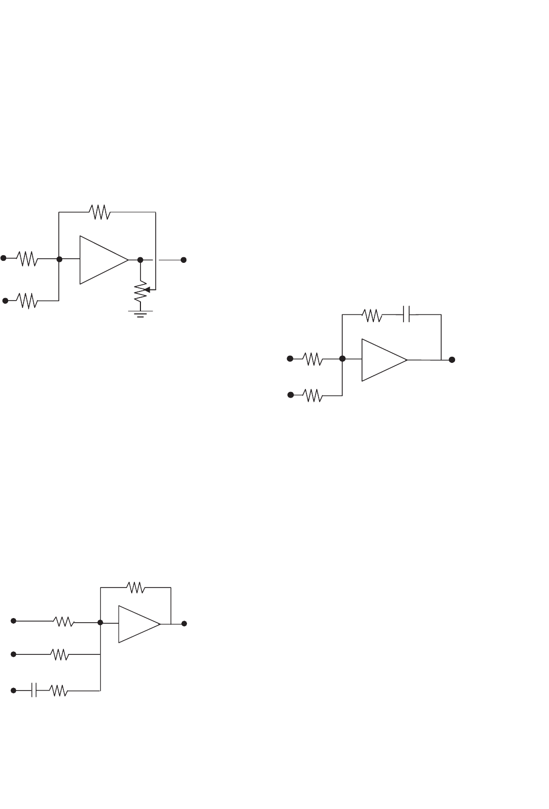
33.7.6.1.1 Proportional Controller A proportional con-
troller provides for a straight gain to amplify the error signal.
It has no discriminatory properties. With the input and feed-
resistance values indicated in Fig. 33.72, the total gain of the
controller is (K + 1).
For this controller, v
c
=
(
K + 1
)(
θ
i
−θ
)
(33.79)
K
c
q
i
q
v
c
FIGURE 33.72 Proportional controller.
33.7.6.1.2 Transient Velocity Feedback Controller It is well-
known that a following error will exist in the preceding system
when a moving or ramp reference is tracked. If a rate feedback,
such as the speed feedback in a position-control system, is used
to damp the system, this error is further increased. To over-
come this following error due to velocity feedback, transient
velocity feedback can be used as indicated in Fig. 33.73.
The speed (velocity) signal is passed through an RC circuit
at the input of the amplifier circuit. An input current occurs
only when the speed signal changes. In the steady state, the
capacitor is fully charged, so that no following error in the
steady state due to the velocity feedback can exist.
In the steady state when the velocities are equal, the output
may lag or lead depending on the relative values of R
1
and R
2
.
It can be shown that in the absence of frictional load torque,
K
c
R
−K
3
w
R
R
R
C
v
c
FIGURE 33.73 Transient velocity feedback controller.
as is often the case in servo applications, no following error is
introduced if R
1
= R
2
.
33.7.6.1.3 Integral Controller In the transient-velocity and
error-rate feedback schemes, the following error will exist if
viscous friction and load torque are present. If such loads
are present, the system gain has to be infinity to have a zero
error. Very large gains will make any physical systems unstable,
unless bandwidth limitations exist. One way to employ infinite
gain in the steady state is to use an integrator. This amplifies
the steady-state error until it is eliminated.
Normally, a proportional plus integral (PI) action is used.
A derivative term is normally not used in the control system of
a drive system, since the drive feedback signals are very noisy.
Instead, derivative signals are obtained through sensors such
as tachogenerators. The structure of a PI controller is indicated
in Fig. 33.74.
K
c
RC
R
R
e
i
= K
1
q
i
e
o
= K
1
q
v
c
FIGURE 33.74 Integral controller.
It can be shown that there will be no steady-state error even
in the presence of frictional or other load torque.
Many types of more complex controllers are available,
such as the variable structure controller. Drives with fuzzy
controllers have also been in the marketplace for some years.
The controller circuits just described are usually imple-
mented in analog circuits using operational amplifiers. Digital
implementations are also being gradually introduced using the
embedded microcontrollers and digital signal processors.
33.7.6.2 Simplified Drive Representations
and Control
Consider the block diagram of Fig. 33.75 in which the individ-
ual elements (blocks) are represented in terms of their transfer
functions in terms of the Laplace operators.
Here, G
A
(s), G
C
(s), G
L
(s), H
T
(s), and H
F
(s) represent the
transfer functions of the power converter plus the motor, the
controller, the load, the sensor (of speed in this example), and
the filter following the sensor respectively. The reference input
for speed and the feedback signal are connected to a summing
junction of an operational amplifier through resistors R
i
and
R
f
, respectively.