Power electronic handbook
Подождите немного. Документ загружается.

866 M. F. Rahman et al.
V
1
s
R
1
L
1
L
m
I
m
E
1
V
2
L
2
R
2
I
1
I
2
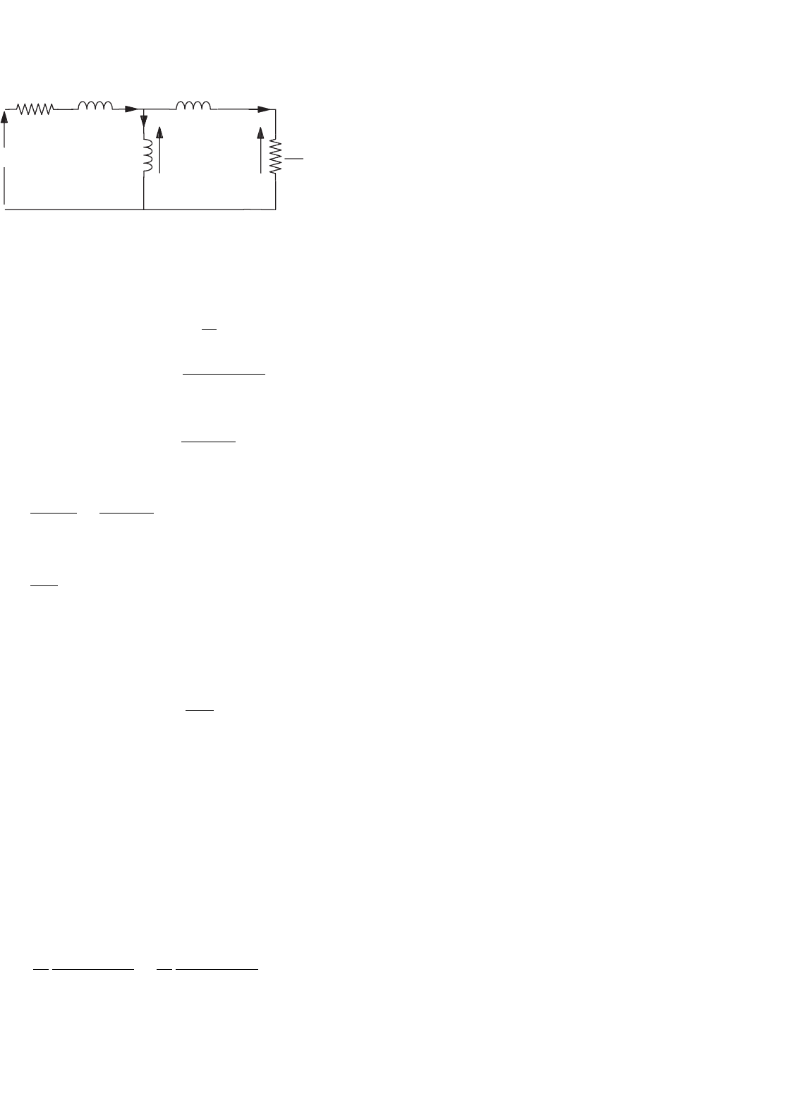
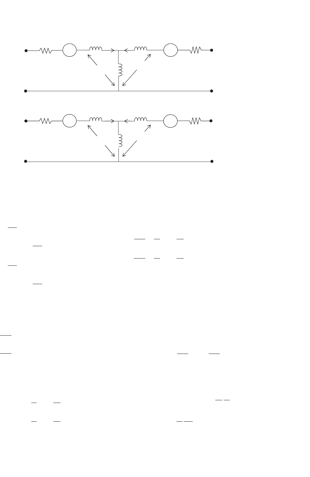
FIGURE 33.13 Steady-state equivalent circuit of an induction motor.
From this representation, the following power relationships
in terms of motor parameters and the rotor slip can be found.
Power in the rotor circuit, P
2
= 3I
2
2
R
2
s
=
3sR
2
E
2
1
R
2
2
+
(
sω
1
L
2
)
2
(33.13)
Output power, P
o
= P
2
−3I
2
2
R
2
= (1 −s)P
2
= ω
0
T =
(1 −s)ω
1
P
T (33.14)
where
slip, s =
ω
1
−ω
r
ω
1
=
ω
1
−pω
o
ω
1
(33.15)
P = number of pole pairs
ω
o
=
2πN
60
rad/s; N is the rotor speed in rev/min,
ω
r
= rotor speed in electrical rad/s,
and
ω
1
= 2πf
1
rad/s (electrical), f
1
being the supply frequency.
The developed torque, T =
P
2
ω
1
/P
Nm (33.16)
The slip frequency, sf
1
, is the frequency of the rotor current
and the airgap voltage E
1
is given by
E
1
= ω
1
L
m
I
m
= ω
1
λ
m
(33.17)
where λ
m
is the stator flux linkage due to the airgap flux. If the
stator impedance is negligible compared to E
1
, which is true
when f
1
is near the rated frequency f
o
,
V
1
≈ E
1
= 2πf
1
λ
m
(33.18)
and
T =
3P
ω
1
sR
2
V
2
1
R
2
2
+
(
sω
1
L
2
)
2
=
3P
ω
1
sR
2
2πf
1
2
λ
2
m
R
2
2
+
(
sω
1
L
2
)
2
(33.19)
33.3.3 Characteristics and Methods of Control
The above analysis suggests several speed-control methods.
The following are the widely used methods:
(1) Stator voltage control,
(2) Slip power control,
(3) Variable-voltage, variable-frequency (V–f ) control,
(4) Variable-current, variable-frequency (I–f ) control.
These methods are sometimes called scalar controls to dis-
tinguish them from vector controls, which are described in
Section 33.3.4. The torque–speed characteristics of the motor
differ significantly under different types of control, as will be
evident in the following sections.
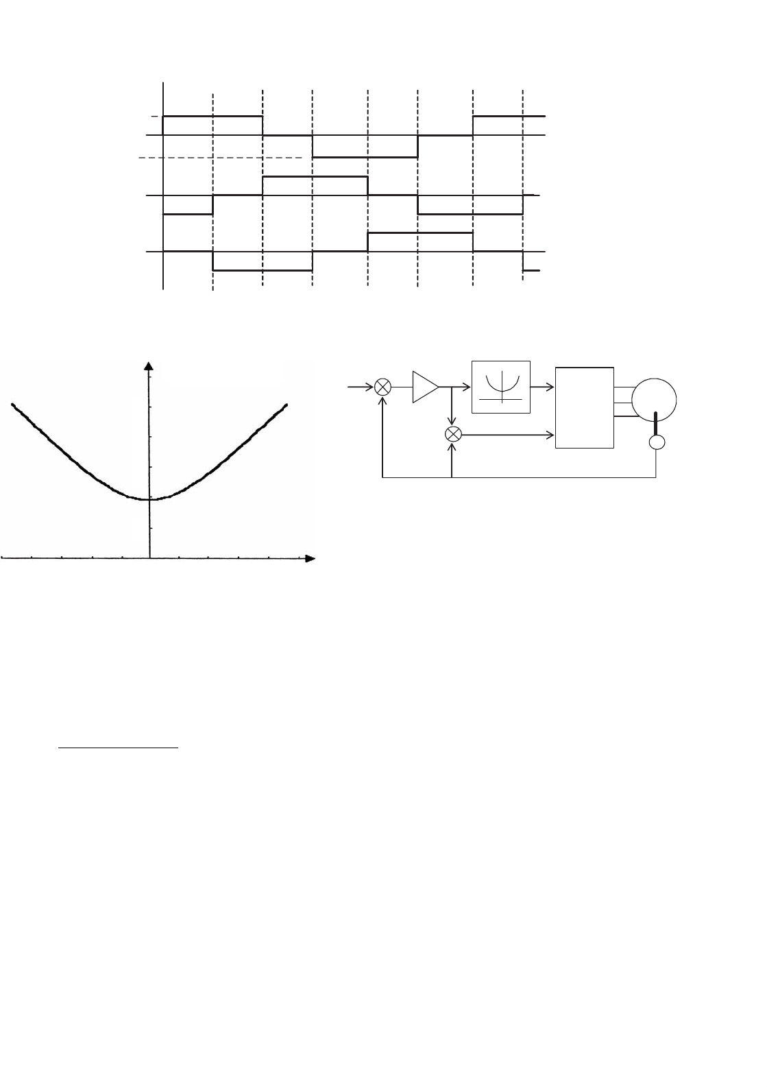
33.3.3.1 Stator Voltage Control
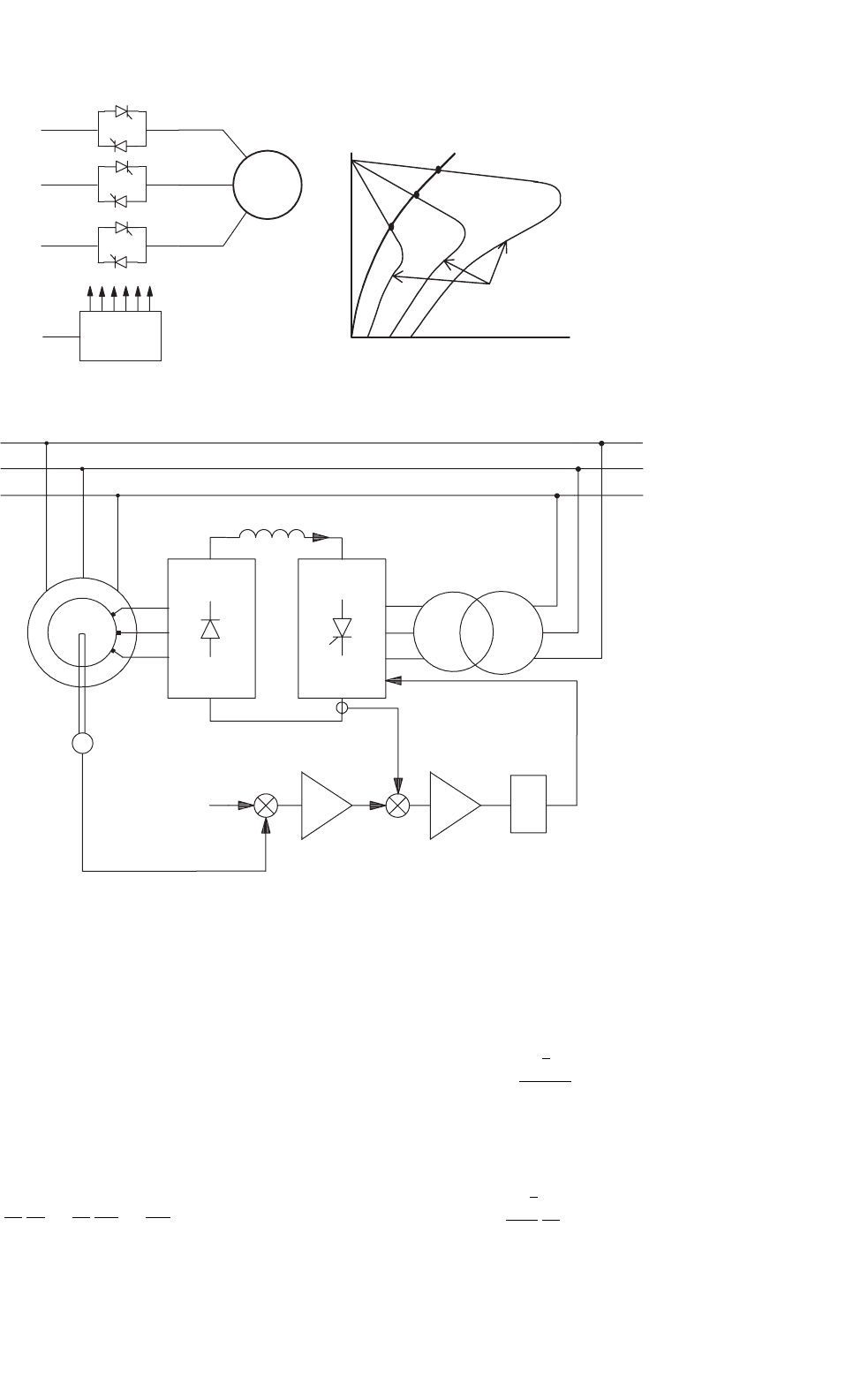
In this method of control, back-to-back thyristors are used to
supply the motor with variable ac voltage, as indicated in the
converter circuit diagram of Fig. 33.14a.
The analysis of Section 33.3.1 implies that the developed
torque varies inversely as the square of the input root mean
square (RMS) voltage to the motor, as indicated in Fig. 33.14b.
This makes such a drive suitable for fan- and impeller-type
loads for which the torque demand rises faster with speed. For
other type of loads, the suitable speed range is very limited.
Motors with high rotor resistance may offer an extended speed
range. It should be noted that this type of drive with back-to-
back thyristors with the firing-angle control suffers from poor
power and harmonic distortion factors when operated at low
speed.
If unbalanced operation is acceptable, the thyristors in one
or two supply lines to the motor may be bypassed. This offers
the possibility of dynamic braking or plugging, desirable in
some applications.
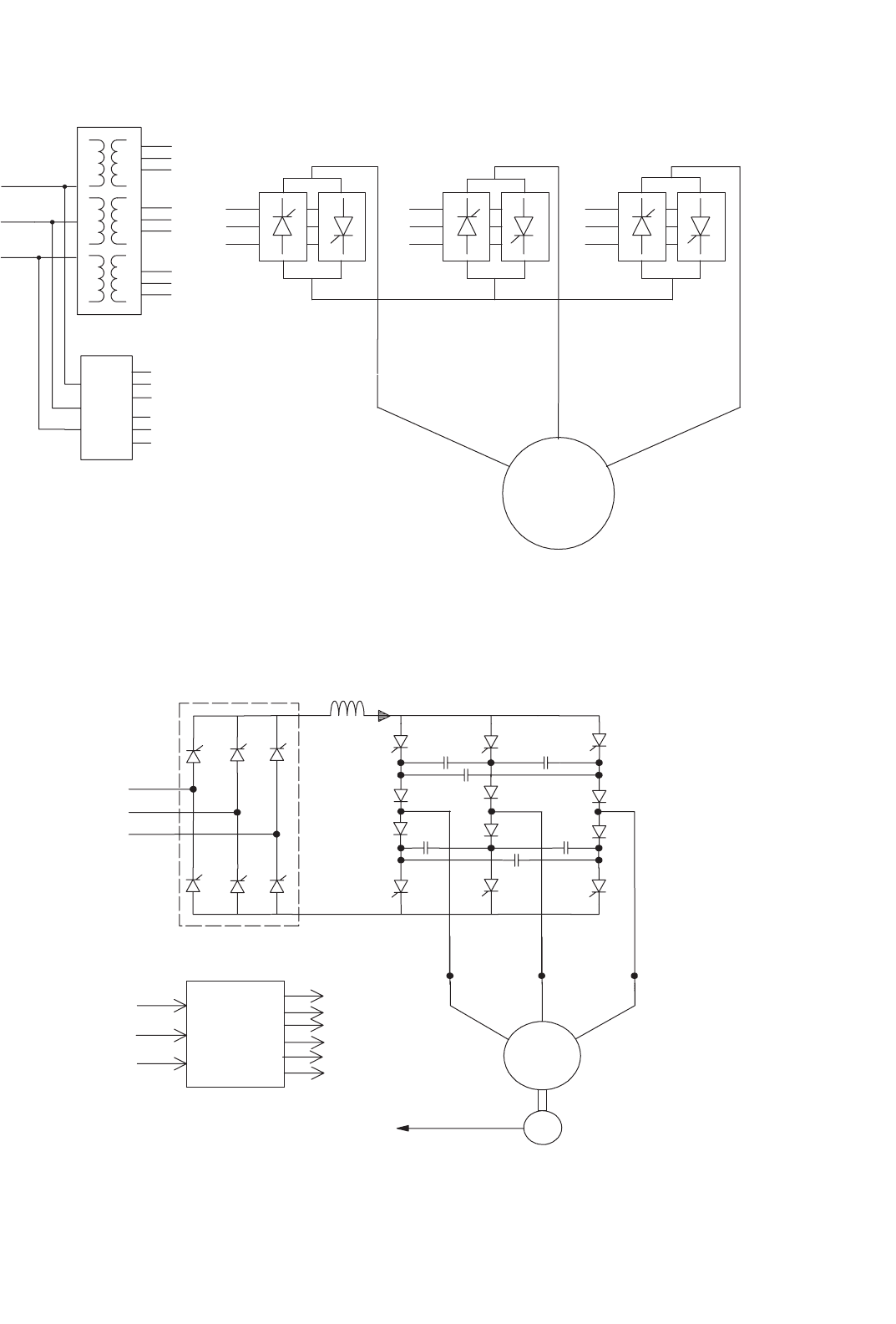
33.3.3.2 Slip Power Control
Variable-speed, three-phase, wound-rotor (or slip-ring)
induction motor drives with slip power control may take sev-
eral forms. In a passive scheme, the rotor power is rectified
and dissipated in a liquid resistor or in a multi-tapped resistor
that may be adjustable and forced cooled. In a more popular
scheme, which is widely used in medium- to large-capacity
pumping installations, the rectified rotor power is returned to
the ac mains by a thyristor converter operating in a naturally
commutated inversion mode. This static Scherbius scheme is
indicated in Fig. 33.15. In this scheme, the rotor terminals are
connected to a three-phase diode bridge which rectifies the
rotor voltage. This rotor output is then inverted into mains
frequency ac by a fully controlled thyristor converter operating
from the same mains as the motor stator.
The converter in the rotor circuit handles only the rotor slip
power, so that the cost of the power converter circuit can be
much less than that of an equivalent inverter drive, albeit at
33 Motor Drives 867
Torque, Nm
V =1 pu
V =0.75 pu
V =0.5 pu
Load T-w
Motor T-w
(a) (b)
IM
V
A
V
B
V
C
e
c
FCC
Speed,
rev/min
FIGURE 33.14 (a) Stator voltage controller and (b) motor and load torque–speed characteristics under voltage control.
T
AC
MAINS
α
ω
ω
ref
e
c
I
d
DC Reactor
FCC
SC
CC
+
+
−
−
FIGURE 33.15 The static Scherbius drive scheme of slip power control.
the cost of the more expensive motor. The dc link current,
smoothed by a reactor, may be regulated by controlling the
firing angle of the converter in order to maintain the developed
torque at the level required by the load. The current controller
(CC) and speed controller (SC) are also indicated in Fig. 33.15.
The current controller output determines the converter firing
angle α from the firing control circuit (FCC).
From the equivalent circuit of Fig. 33.13 and ignoring the
stator impedance, the RMS voltage per phase in the rotor
circuit is given by
V
R
=
V
s
n
ω
r
ω
s
=
V
s
n
sω
s
ω
s
=
V
s
s
n
(33.20)
where ω
s
and ω
r
are the angular frequencies of the voltages in
the stator and rotor circuits, respectively, and n is the ratio of
the equivalent stator to rotor turns. The dc-link voltage at the
rectifier terminals of the rotor, v
d,
is given by
v
d
=
3
√
6V
R
π
Assuming that the transformer interposed between the
inverter output is and the ac supply has the same turns ratio
n as the effective stator-to-rotor turns of the motor,
v
d
=−
3
√
6
π
V
s
n
cos α (33.21)
868 M. F. Rahman et al.
The negative sign arises because the thyristor converter
develops negative dc voltage in the inverter mode of oper-
ation. The dc-link inductor is mainly to ensure continuous
current through the converter so that the expression (33.21)
holds for all conditions of operation. Combining the preceding
three equations gives
sω
s
=−ω
s
cos α so that, s =−n cos α
and the rotor speed
ω
o
=
1
P
(
1 −s
)
ω
s
=
1
P
ω
s
(
1 +n cos α
)
rad/s (33.22)
Thus, the motor speed can be controlled by adjusting the
firing angle α. By varying α between 180
◦
and 90
◦
, the speed of
the motor can be varied from zero to full speed, respectively.
For a motor with low rotor resistance and with the assump-
tions taken earlier, it can be shown that the developed torque
of the motor is given by
T = 3P
V
s
ω
s
i
d
≈ 3Pλ
m
i
d
Nm (33.23)
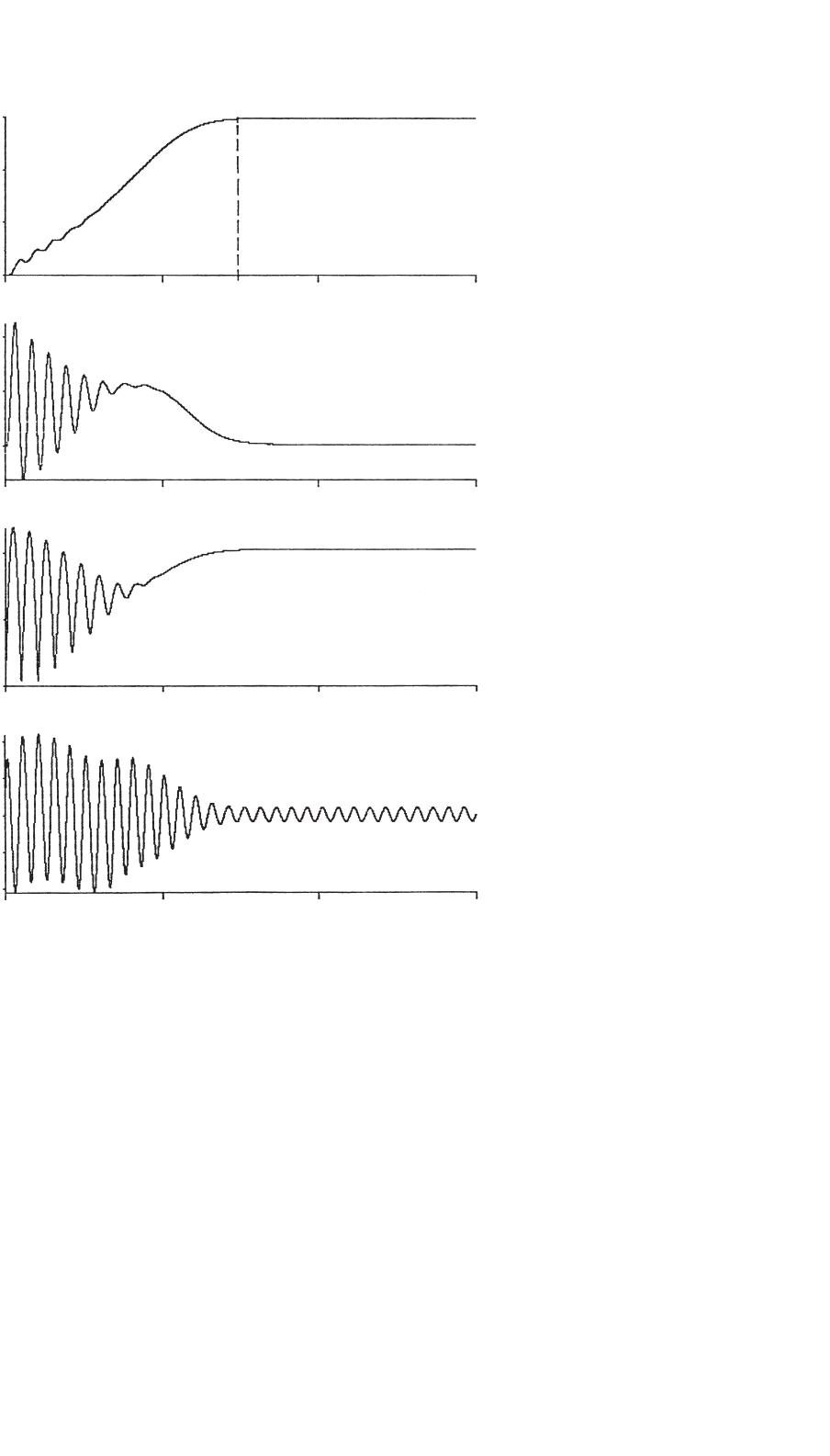
where i
d
is the dc-link current. Thus, the inner torque control
loop of a variable-speed drive using the Scherbius scheme nor-
mally employs a dc-link current loop as the innermost torque
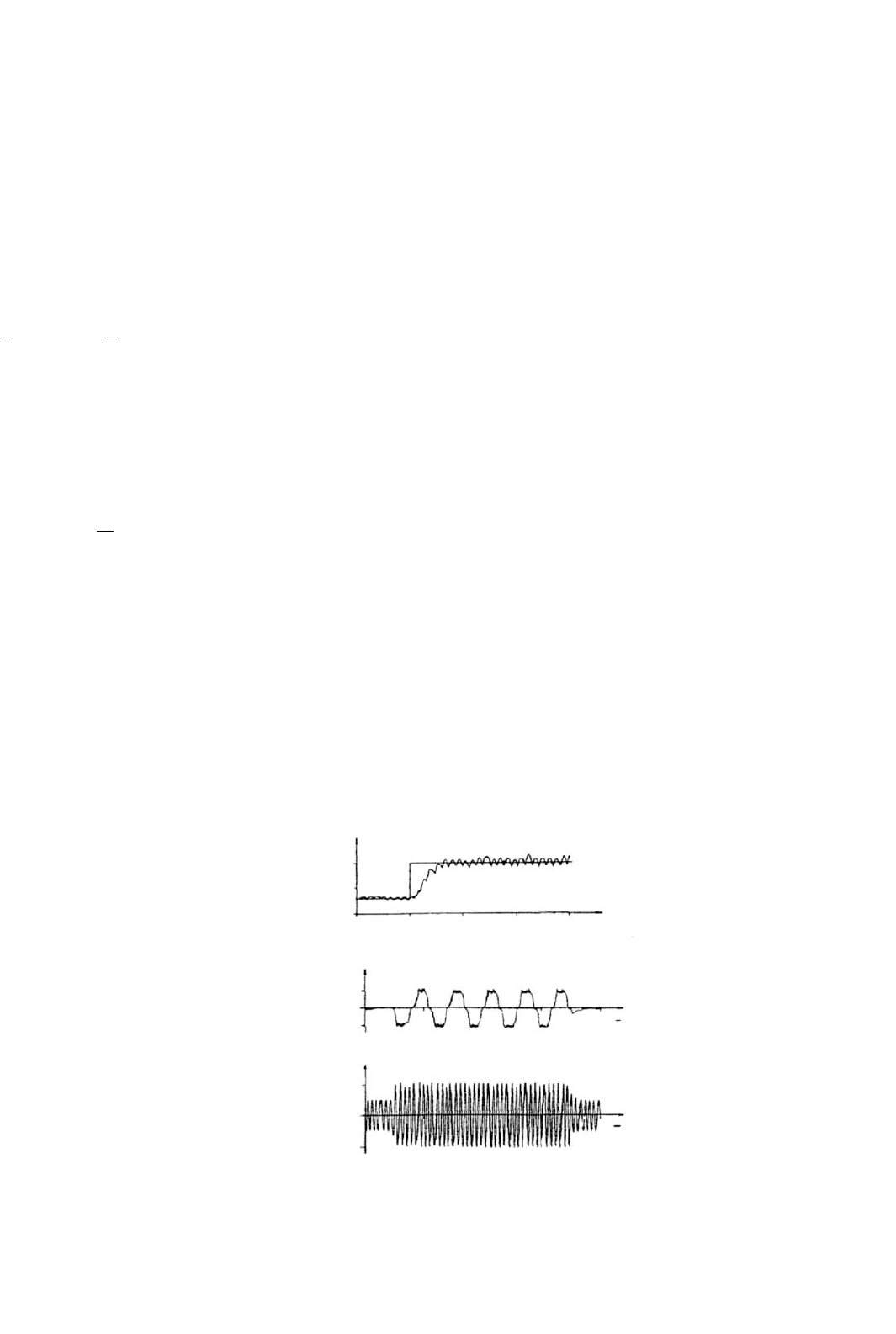
loop. Figure 33.16 shows the transient responses of the dc-
link, rotor and stator currents of such a drive when the motor
is accelerated between two speeds.
The drive is normally started with a short-time-rated liquid
resistor, and the thyristor speed controller is started when the
drive reaches a certain speed.
By replacing the diode rectifier of Fig. 33.16 with another
thyristor bridge, power can be made to flow to and from the
Step response of dc link current
control loop
Rotor current during step change
Stator current during step change
i
D
/A
50
25
0
i
R
/A
50
0
−50
i
S
/A
44
0
−44
025
0.25 0.5 0.75 1.0
t
s
t
s
50 75 100
t/ms
FIGURE 33.16 Transient responses of a slip power controlled drive under acceleration.
rotor circuit, allowing the motor to operate at a rate higher
than synchronous speed. For very large drives, a cycloconverter
may also be used in the rotor circuit with direct conversion of
frequency between the ac supply and the rotor and driving the
motor above and below synchronous speed.
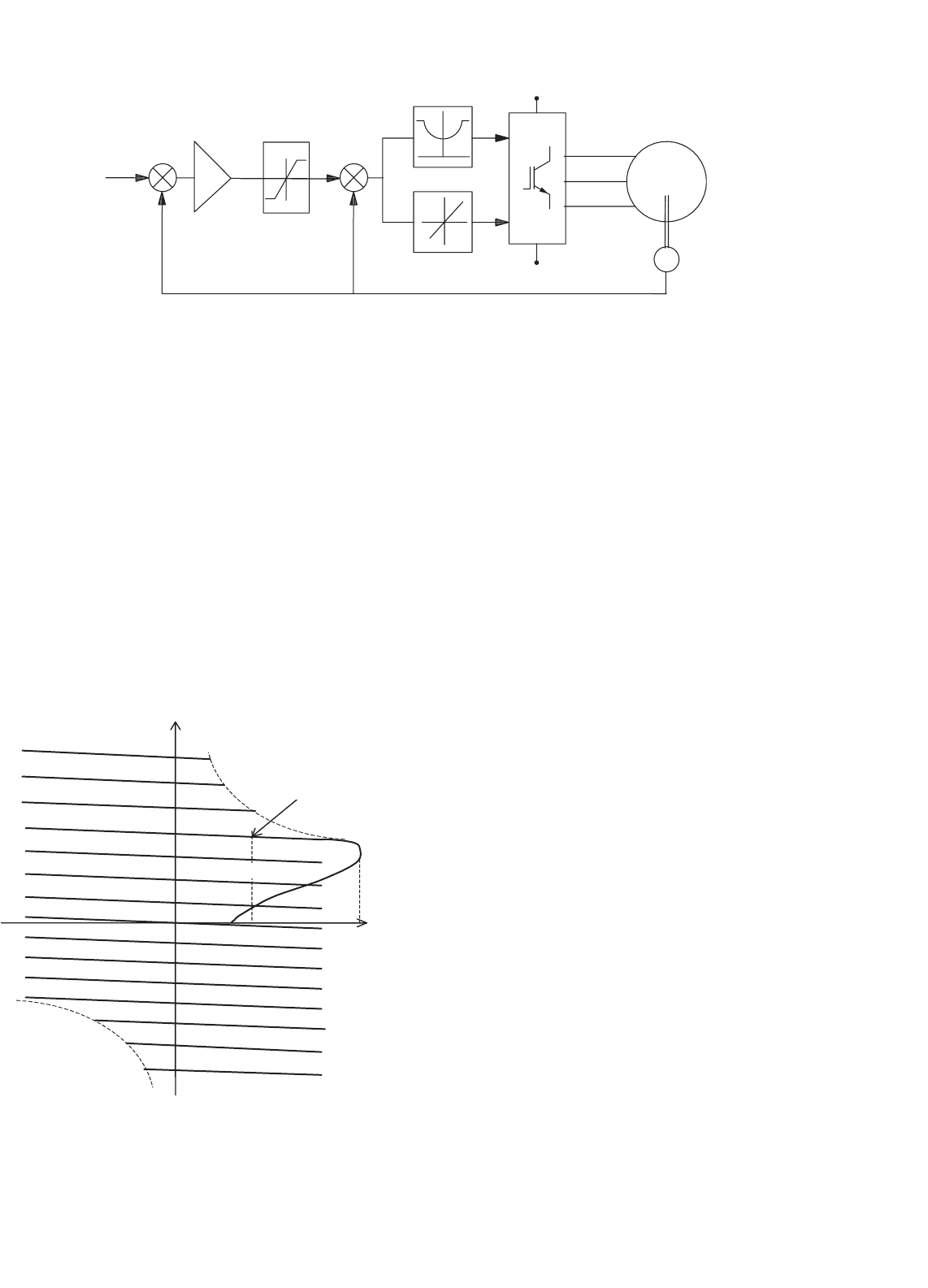
33.3.3.3 Variable-voltage, Variable-frequency (V–f )
Control
33.3.3.3.1 SPWM Inverter Drive When an induction motor
is driven from an ideal ac voltage source, its normal operating
speed is less than 5% below the synchronous speed, which
is determined by the ac source frequency and the number of
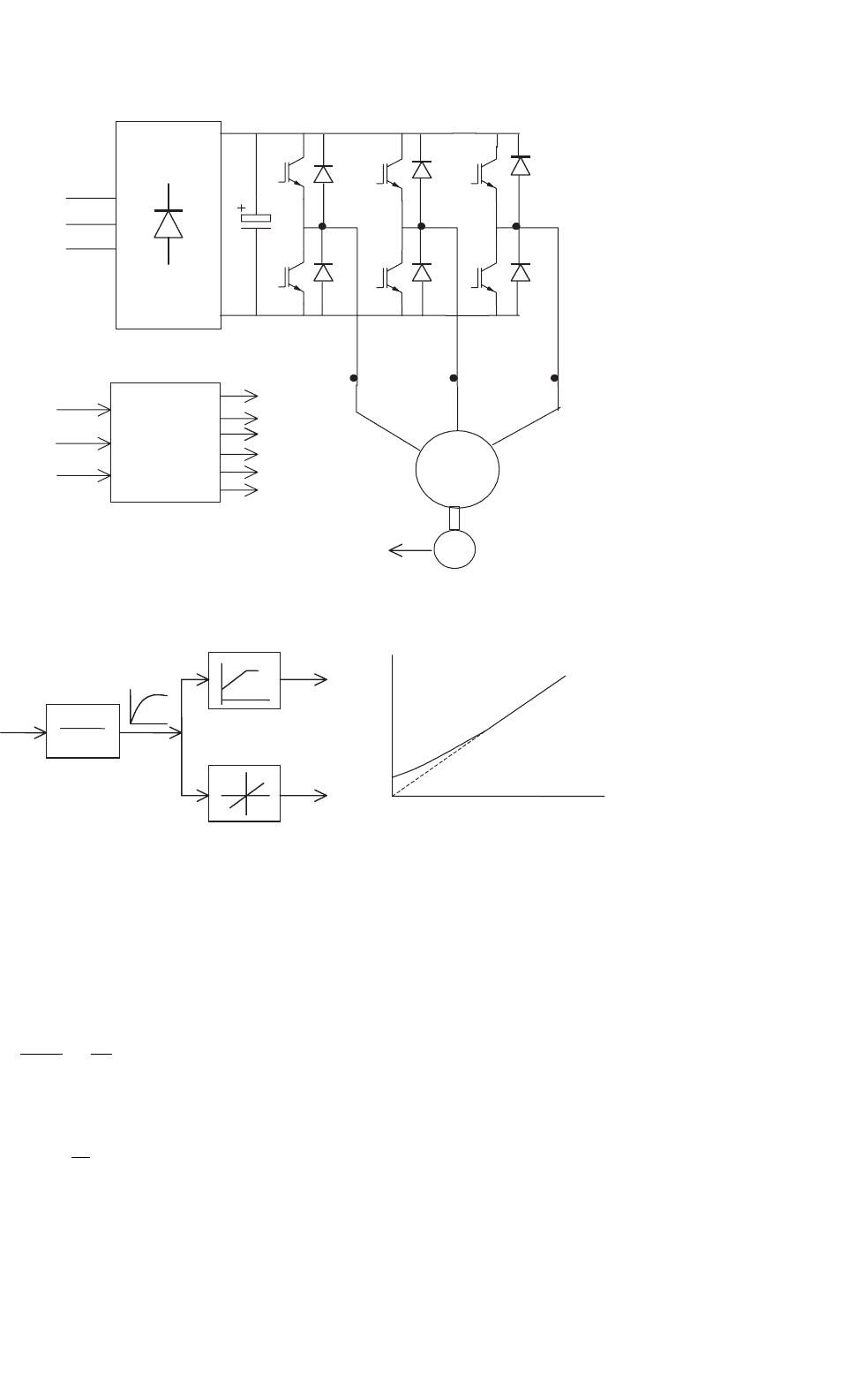
motor poles. With a sinusoidally modulated (SPWM) inverter,
indicated in Fig. 33.17, the supply frequency to the motor can
be easily adjusted for variable speed. Equation (33.18) implies
that, if rated airgap flux is to be maintained at its rated value
at all speeds, the supply voltage V
1
to the motor should be
varied in proportion to the frequency f
1
. The block diagram of
Fig. 33.18a shows how the frequency f
1
and the output voltage
V
1
of the SPWM inverter are proportionately adjusted with
the speed reference. The speed reference signal is normally
passed through a filter that only allows a gradual change in
the frequency f
1
. This type of control is widely referred to as
the V–f inverter drive. Control of the stator input voltage V
1
as a function of the frequency f
1
is readily arranged within
the inverter by modulating the switches T
1
–T
6
. At low speed,
however, where the input voltage V
1
is low, most of the input
voltage may drop across the stator impedance, leading to a
reduction in airgap flux and loss of torque.
Compensation for the stator resistance drop, as indicated in
Fig. 33.18b, is often employed. However, if the motor becomes
lightly loaded at low speed, the airgap flux may exceed the rated
value, causing the motor to overheat.
33 Motor Drives 869
AC
Mains
T
1
D
1
D
4
D
6
D
2
D
3
D
5
T
1
T
4
T
3
T
6
T
5
T
2
T
3
T
5
T
6
T
2
T
4
M
T
P
W
M
e
c1
e
c2
e
c3
−V
DC
+V
DC
w
FIGURE 33.17 V–f drive with SPWM inverter.
1+T
f
s
1
Speed
reference
V
1
V
1
reference
f
1
reference
Compensated
(a) (b)
Ideal
f
1
FIGURE 33.18 (a) Input reference filter and voltage and frequency reference generation for the V–f inverter drive and (b) voltage compensation at
low speed.
From the equivalent circuit of Fig. 33.13 and neglecting the
rotor leakage inductance, the developed torque T and the rotor
current I
2
are given by
I
2
=
E
1
sω
1
R
2
ω
1
=
λ
m
R
2
sω
1
(33.24)
and
T = 3P
R
2
ω
r
I
2
2
(33.25)
where sω
1
is the slip frequency, which is also the frequency of
the voltages and currents in the rotor. Equation (33.24) implies
that by limiting the slip s, the rotor current can be limited,
which in turn limits the developed torque Eq. (33.25). Con-
sequently, a slip-limited drive is also a torque-limited drive.
Note that this is true only in steady state. A speed-control sys-
tem with such a slip limiter is shown in Fig. 33.19. In this
scheme, the motor speed is sensed and added to a limited
speed error (or limited slip speed) to obtain the frequency (or
speed reference for the V–f drive).
Many applications of the V–f controller, however are open-
loop schemes, in which any demanded variation in V
1
is passed
through a ramp limiter (or filter) so that sudden changes in
the slip speed ω
r
are precluded, thereby allowing the motor to
follow the change in the supply frequency without exceeding
the rotor current and torque limits.
870 M. F. Rahman et al.
+
−
ω
ref
ω
ω
ω
∗
2
IM
T
v
1
f
1
+
+
Speed Controller
FIGURE 33.19 Closed-loop speed controller with an inner slip loop.
From the foregoing analyses, it is obvious that the V–f
inverter drive essentially operates in all four quadrants, with
rotor speed dropping slightly with the load, and develop-
ing full torque at the same slip speed at all speeds. This
assumes that the stator input voltage is properly compensated,
so that the motor is operated with constant (or rated) air-
gap flux at all speed. The motor can be operated above the
base speed by keeping the input voltage V
1
constant, while
increasing the stator frequency above base frequency in order
to run the motor at speeds higher than the base speed. The
airgap flux and hence the maximum developed torque now
fall with speed, leading to constant power type characteristic.
Figure 33.20 depicts the T–ω characteristics of such a voltage-
and frequency-controlled drive for various operating frequen-
cies. In this figure, the T–ω characteristic for base speed has
been drawn in full, indicating the maximum developed torque
ω, rad/sec
T, Nm
T
max
T
rated
Sequence: a-b-c
Sequence: a-c-b
Base speed
with rated V
1
and base f
1
Q
1
Q
2
Q
3
Q
4
FIGURE 33.20 Typical T–ω characteristics of V–f drive with the input
frequency f
1
and voltage V
1
below and above base speed.
T
max
and the rated torque. Below base speed, the V
1
–f
1
ratio is
maintained to keep the airgap flux constant. Above base speed,
V
1
is kept constant, while f
1
increases with speed, thus weaken-
ing the airgap flux. Forward driving in quadrant 1 takes place
with the inverter output voltage sequence of a–b–c, whereas
reverse driving in quadrant 3 takes place with the sequence
a–c–b. Regenerative braking while forward driving takes place
by adjusting the input frequency f
1
in such a way that the
motor operates in quadrant 2 (quadrant 4 for reverse braking)
with the desired braking characteristic.
Note that the characteristics in Fig. 33.20 are based on the
steady-state equivalent circuit model of the motor. Such a
drive suffers from the poor torque response during transient
operation because of time-dependent interactions between the
stator and rotor fluxes. Figure 33.21 indicates the machine air-
gap flux during acceleration with V-f control obtained from
a dynamic model. Clearly, the airgap flux does not remain
constant during the dynamic operation.
33.3.3.3.2 Cycloconverter Drive For large-capacity induc-
tion motor drives, the variable-frequency supply at variable
voltage is effectively obtained from a cycloconverter in which
a back-to-back thyristor converter pairs are used, one for each
phase of the motor, as indicated in Fig. 33.22. Each thyristor
block in this figure represents a fully controlled thyristor ac–dc
converter. The maximum output frequency of such a con-
verter can be as high as about 40% of the supply frequency. In
view of the large number of thyristor switches required, cyclo-
converter drives are suitable for large capacity but low-speed
applications.
33.3.3.4 Variable Current–Variable Frequency (I–f)
Control
In this scheme, medium- to large-capacity induction motors
are driven from a variable but stiff current supply that may
be obtained from a thyristor converter and a dc-link induc-
tor as indicated in Fig. 33.23. The frequency of the current
supply to the motor is adjusted by a thyristor converter with
33 Motor Drives 871
Speed, r/minTorque, NmAirgap flux, TeslaStator current, A
1500
100
1
0.5
0
40
20
0
−20
−40
50
0
1000
500
0
0 0.2 0.314 0.4 0.6
0 0.2 0.4 0.6
0 0.2 0.4 0.6
0 0.2 0.4 0.6
T, Sec.
(a)
(b)
(c)
(d)
FIGURE 33.21 Transient response of torque, speed, current, and airgap flux during acceleration from standstill using a V–f inverter drive.
auxiliary diodes and capacitors. The diodes in each inverter
leg and the capacitors across them are needed for turning off
the thyristors when current is to be commutated from one to
the next in sequence. The motor current waveforms are nor-
mally six-step, or quasi-square, as indicated in Fig. 33.24. The
switching states of the inverter thyristors are also indicated in
this figure. The motor voltage waveforms are determined by
the load. These waveforms are more nearly sinusoidal than the
current waveforms.
The thyristor converter supplying the quasi-square current
waveforms to the motor has firing-angle control, in order to
regulate the dc-link current to the inverter. The dynamics
of the dc-link current control is such that this current may
be considered to be constant during the time, the inverter
switches commutate the dc-link current from one switch to the
next. Such a current-source drive offers four-quadrant oper-
ation, with independent control of the dc-link current and
output frequency. One drawback is that the motor voltage
waveforms have voltage spikes due to commutation.
From the analysis of Section 33.3.2, if the higher order har-
monics of the current waveforms in Fig. 33.24 are neglected,
and it is assumed that the motor voltage and current wave-
forms are taken to be sinusoidal, the magnetizing current I
m
in Fig. 33.13 can be kept constant (for constant-airgap flux
872 M. F. Rahman et al.
V
SA
V
SA
V
SB
V
SB
V
SC
V
SC
TRANSFORMER BANK
A
B
C
FCC
MOTOR
AC SUPPLY
FIGURE 33.22 V–f drive with cycloconverter drive.
T
1
T
6
T
3
T
5
T
2
T
4
T
1
T
4
T
3
T
6
T
5
T
2
M
T
e
c1
e
c2
e
c3
FCC
C
C
C
C
C
C
L
Inverter
Rectifier
AC
Mains
w
FIGURE 33.23 DC-link current-source thyristor inverter drive.
33 Motor Drives 873
T
1
T
6
T
3
T
3
T
4
T
4
T
5
T
5
T
6
T
6
T
1
T
2
T
2
T
1
i
a
i
b
i
c
−I
d
−I
d
+I
d
+I
d
FIGURE 33.24 Motor-current waveforms and the thyristor switching states for a current-source drive.
Stator current (A)
10
8
6
4
2
−5 −4 −3 −2 −10
Rotor frequency (Hz)
12345
FIGURE 33.25 Stator current vs rotor (slip) frequency for constant-
airgap flux operation.
operation) if the RMS value of the stator supply current I
1
is defined according to Eq. (33.26). This relationship is also
shown in graphical form in Fig. 33.25.
I
m
= I
1
R
2
2
+
2πf
1
sL
2
2
R
2
2
+2πf
1
(
L
2
+L
m
)
2
1/2
= constant (33.26)
The control scheme for variable-speed operation with a
current-source drive is indicated in the block diagram of
Fig. 33.26. The speed reference defines the stator current ref-
erence according to Eq. (33.26) and the frequency reference
is obtained by adding the rotor frequency to the actual speed
of the motor. The inverter drive may consist of the thyris-
tor current source and the inverter of Fig. 33.23 or a diode
rectifier supplied SPWM transistor inverter of Fig. 33.17 with
independent current regulators, one for each phase.
The dynamic performance of such current-controlled
induction motor drives is not very satisfactory, just as for
M
I
1
f
1
+
−
+
+
INVERTER
w
ref
w
w
r
w
FIGURE 33.26 Variable-current–variable-frequency inverter drive
scheme.
the voltage-source inverters. Furthermore, the current-source
inverter drive cannot normally be operated open-loop, like
the V–f inverter drive. For high dynamic performance, vector-
controlled drives are becoming popular.
33.3.4 Vector Controls
The foregoing scalar control methods are only suitable for
adjustable speed applications in which the load speed or posi-
tion is not controlled like in a servo system. Instantaneous
frequency control with a view to control motor speed or posi-
tion cannot be defined, and therefore, instantaneous torque
control cannot be addressed by scalar control methods. Vec-
tor control technique allows a squirrel-cage induction motor
to be driven with high dynamic performance, comparable to
that of a dc motor. In vector control, machine dynamic model
rather than steady-state model (on which scalar controllers are
based on), is used to design the controller. For this, the con-
troller needs to know the rotor speed (in the indirect method)
or the airgap flux vector (in the direct method) accurately,
using sensors. The latter method is not practical because of
the requirement of attaching airgap flux sensors. The indi-
rect method, which is being widely accepted in recent years,
requires the controller to be matched with the motor being
driven. This is because the controller also needs to know

874 M. F. Rahman et al.
some rotor parameter(s), which may vary according to the
conditions of operation, continuously.
33.3.4.1 Basic Principles
The methods of vector control are based on the dynamic equiv-
alent circuit of the induction motor. There are at least three
fluxes (rotor, airgap, and stator) and three currents or mmfs
(stator, rotor, and magnetizing) in an induction motor. For
high dynamic response, interactions among current, fluxes,
and speed, must be taken into account in determining appro-
priate control strategies. These interactions are understood
only via the dynamic model of the motor.
All fluxes rotate at synchronous speed. The three-phase
currents create mmfs (stator and rotor) that also rotate at
synchronous speed. Vector control aligns axes of an mmf and
a flux orthogonally at all times. It is easier to align the stator
current mmf orthogonally to the rotor flux.
Any three-phase sinusoidal set of quantities in the stator can
be transformed to an orthogonal reference frame by
f
αs
f
βs
f
o
=
2
3
cos θ cos(θ −
2π
3
) cos(θ −
4π
3
)
sin θ sin(θ −
2π
3
) sin(θ −
4π
3
)
1
2
1
2
1
2
f
as
f
bs
f
cs
(33.27)
where θ is the angle of the orthogonal set α–β–0 with respect
to any arbitrary reference. If the α–β–0 axes are stationary and
the α-axis is aligned with the stator a-axis, then θ = 0atall
times, Thus
f
αs
f
βs
f
os
=
2
3
1 −
1
2
−
1
2
0
√
3
2
√
3
2
1
2
1
2
1
2
f
as
f
bs
f
cs
(33.28)
If the orthogonal set of reference rotates at the synchronous
speed ω
1
, its angular position at any instant is given by
θ =
t
0
ω
1
t +θ
o
(33.29)
The orthogonal set is then referred to as d–q–0 axes. The
three-phase rotor variables, transformed to the synchronously
rotating frame, are
f
dr
f
qr
f
o
=
2
3
cos
(
ω
e
−ω
r
)
t cos
(
ω
e
−ω
r
)
t −
2π
3
cos
(
ω
e
−ω
r
)
t −
4π
3
sin
(
ω
e
−ω
r
)
t sin
(
ω
e
−ω
r
)
t −
2π
3
sin
(
ω
e
−ω
r
)
t −
4π
3
1
2
1
2
1
2
×
f
ar
f
br
f
cr
(33.30)
It should be noted that the difference ω
e
−ω
r
is the relative
speed between the synchronously rotating reference frame and
the frame attached to the rotor. This difference is also the slip
frequency, ω
sl
, which is the frequency of the rotor variables.
By applying these transformations, voltage equations of the
motor in the synchronously rotating frame reduce to
v
qs
v
ds
v
qr
v
dr
=
R
s
+pL
s
ω
e
L
s
pL
m
ω
e
L
m
−ω
e
L
s
R
s
+pL
s
−ω
e
L
m
pL
m
pL
m
(ω
e
−ω
r
)L
m
R
r
+pL
r
(ω
e
−ω
r
)L
r
−(ω
e
−ω
r
) pL
m
−(ω
e
−ω
r
)L
r
R
r
+pL
r
×
i
qs
i
ds
i
qr
i
dr
(33.31)
where the speed of the reference frame, ω
e
, is equal to ω
1
and
L
s
= L
ls
+L
m
, L
r
= L
lr
+L
m
.
Subscripts l and m stand for leakage and magnetizing,
respectively, and p represents the differential operator d/dt.
The equivalent circuits of the motor in this reference frame
are indicated in Figs. 33.27a and b.
The stator flux linkage equations are:
λ
qs
= L
ls
i
qs
+L
m
(i
qs
+i
qr
) = L
s
i
qs
+L
m
i
qr
(33.32)
λ
ds
= L
ls
i
ds
+L
m
(i
ds
+i
dr
) = L
s
i
ds
+L
m
i
dr
(33.33)
ˆ
λ
s
=
λ
2
qs
+λ
2
ds
(33.34)
The rotor flux linkages are given by
λ
qr
= L
lr
i
qr
+L
m
(i
qs
+i
qr
) = L
r
i
qr
+L
m
i
qs
(33.35)
λ
dr
= L
lr
i
dr
+L
m
(i
ds
+i
dr
) = L
r
i
dr
+L
m
i
ds
(33.36)
ˆ
λ
r
=
λ
2
qr
+λ
2
dr
(33.37)
The airgap flux linkages are given by
λ
mq
= L
m
i
qs
+i
qr
(33.38)
λ
md
= L
m
(
i
ds
+i
dr
)
(33.39)
ˆ
λ
m
=
λ
2
mqs
+λ
2
mds
(33.40)
The torque developed by the motor is given by
T =
3P
2
λ
ds
i
qs
−λ
qs
i
ds
(33.41)
33 Motor Drives 875
+
−
+
R
s
R
s
L
ls
L
ls
L
lr
L
lr
L
m
L
m
R
r
R
r
−
i
qs
i
ds
i
qr
i
dr
v
qr
v
dr
v
qs
v
ds
(a)
(b)
+
−
+
−
w
e
l
ds
w
e
l
qs
(w
e
- w
r
)l
dr
(w
e
- w
r
)l
qr
l
qr
l
dr
l
qs
l
ds
FIGURE 33.27 Motor dynamic equivalent circuits in the synchronously rotating: (a) q- and (b) d-axes.
From Eq. (33.31), the rotor voltage equations are
v
qr
= 0 = L
m
di
qs
dt
+
(
ω
e
−ω
r
)
L
m
i
ds
+
R
r
i
r
+L
r
di
qr
dt
+
(
ω
e
−ω
r
)
L
r
i
d
r (33.42)
v
dr
= 0 = L
m
di
ds
dt
+
(
ω
e
−ω
r
)
L
m
i
qs
+
R
r
i
r
+L
r
di
dr
dt
+
(
ω
e
−ω
r
)
L
r
i
qr
(33.43)
Using Eqs. (33.35) and (33.36),
dλ
qr
dt
+R
r
i
qr
+(ω
e
−ω
r
)λ
dr
= 0 (33.44)
and
dλ
dr
dt
+R
r
i
dr
+(ω
e
−ω
r
)λ
qr
= 0 (33.45)
Also from Eqs. (33.35) and (33.36),
i
qr
=
1
L
r
λ
qr
−
L
m
L
r
i
qs
(33.46)
i
dr
=
1
L
r
λ
dr
−
L
m
L
r
i
ds
(33.47)
The rotor currents i
qr
and i
dr
can be eliminated from
Eqs. (33.44) and (33.45) by using Eqs. (33.46) and (33.47).
Thus
dλ
qr
dt
+
L
r
R
r
λ
qr
−
L
m
L
r
R
r
i
qs
+(ω
e
−ω
r
)λ
dr
= 0 (33.48)
dλ
dr
dt
+
R
r
L
r
λ
dr
−
L
m
L
r
R
r
i
ds
+(ω
e
−ω
r
)λ
qr
= 0 (33.49)
The elimination of transients in rotor flux and the coupling
between the two axes occurs when
λ
qr
= 0 and
ˆ
λ
r
= λ
dr
(33.50)
The rotor flux should also remain constant so that
dλ
dr
dt
= 0 =
dλ
qr
dt
(33.51)
From Eq. (33.48) to Eq. (33.51),
ω
e
−ω
r
= ω
sl
=
L
m
ˆ
λ
r
R
r
L
r
i
qs
(33.52)
and
L
r
R
r
d
ˆ
λ
r
dt
+
ˆ
λ
r
= L
m
i
ds
(33.53)