Power electronic handbook
Подождите немного. Документ загружается.


32 Drives Types and Specifications 845
TABLE 32.14 Comparison between different MV converter stack topologies
Topologies Advantages Disadvantages
2-level with series devices
(SC2L)
• Simple & proven technology
• Same converter design over supply voltage range
• Standard fully developed PWM control
• Provision for series redundancy of power switches per
inverter phase arm (n+1)
• Static and dynamic voltage sharing of series devices
• High dV/dt due to synchronous commutation of series
devices
• High switching frequency harmonic content in inverter
output voltage
3-level NPC (3LNPC)
• Well-proven
• Reduced harmonic content
• Better utilization of switches
• Reduced dV/dt (half the SC2L equivalent)
• Series redundancy is difficult to achieve
• More complex PWM control is needed, than 2 level
• Requires extra clamping diodes
• Requires split DC link
• Requires mid-point voltage balance control
• Even number of power devices per arm is always needed
• Switches requires snubbers
Diode clamped multi-level
(DCML)
• Reduced harmonic contents
• Reduced dV/dt
• Series redundancy is very difficult to achieve
• Very complex PWM control is needed
• Requires many steering diodes
• Requires split DC link
• Requires voltage balance control of split DC link capaci-
tors
• Uneven current stresses on power devices
• Requires snubbers
Capacitor clamped
multi-level (CCML)
• This configuration has all the advantages of a multi-level
converter plus Simpler arrangement, modular building
block
• Less components
•
Snubberless operation is possible
• Easier capacitor voltage balance than 3LNPC
• Possible parasitic resonance between decoupling capaci-
tors
• Complex to provide series redundancy
• More complex PWM control strategy than for 2-level
• Voltage redistribution of capacitors during supply voltage
surges
• Too many capacitors (bulky stack design & poor capaci-
tor utilization at high ratings)
• Complex converter arrangement (for low stray induc-
tance)
• Inverter rating is limited by the load current flowing
through the capacitors
Series connected isolated
h-bridges (ISHB)
• Modular design of the converter power modules
• The basic building block is based on a DC supply bridge,
decoupling capacitor and a H-bridge arrangement
•
In the AC supply the combined diode bridge rectifiers
act like a multi-pulse bridge (18p for 4-level and 24p for
5-level), reducing harmonic injection into the AC supply.
• Its output has very low harmonic contents in spite of the
low switching frequency
• Employs a special (bulky and expensive) transformer
• Complex to achieve series redundancy
• Different supply transformer designs are required for
applications operating at different AC line voltages
• Power pulsation for poor power factor loading
• Poor utilization of capacitors
• Not suitable for common DC bus applications
• Dynamic Braking difficult
32.6.4 Communication in VSDs
The use of a high speed advanced digital communication
(Fieldbus) to build industrial automation system for real-time
control or simply for data logging has become well-established
in modern industries. Digital communication resulted in
replacing wiring looms with a digital serial network, this
resulted in a lower cost installation and a more reliable
solution. Over the last few years many industrial Fieldbuses
emerged and endusers, system integrators and original equip-
ment manufacturers (OEMs) chose the optimum system for
their applications.
A Fieldbus is a digital communication system that allows a
control system to exchange data with remote sensors, actuators
and drives, using a single communication link. The major ben-
efits seen are (a) reduced installation and cabling cost, and
better overall immunity of the system. Both factors result in
more reliable operation and reduced maintenance costs.
There exist two main types of network:
(a) Centralized network – requires a network master con-
troller, typically a PLC. The master device is entirely
responsible for controlling communications over the
network, while the slave devices tend to be “dumb”
devices with no local intelligence.
(b) Decentralized network – which require some local
intelligence at each node, but no overall mas-
ter device. This is ideal for real time application
846 Y. Shakweh
Speed
Control
Torque
Control
Torque
Control
Torque &
Flux Control
Optimal
Pattern
AC
Motor
Speed
Feedback
(d)
(c)
(b)
(a)
Vector
Control
DC
Motor
AC
Motor
AC
Motor
T
PWM
Modulator
PWM
Modulator
Speed
Feedback
V/f
Ratio
V
f
V
f
Frequency
Refernce
Speed
Control
Speed
Control
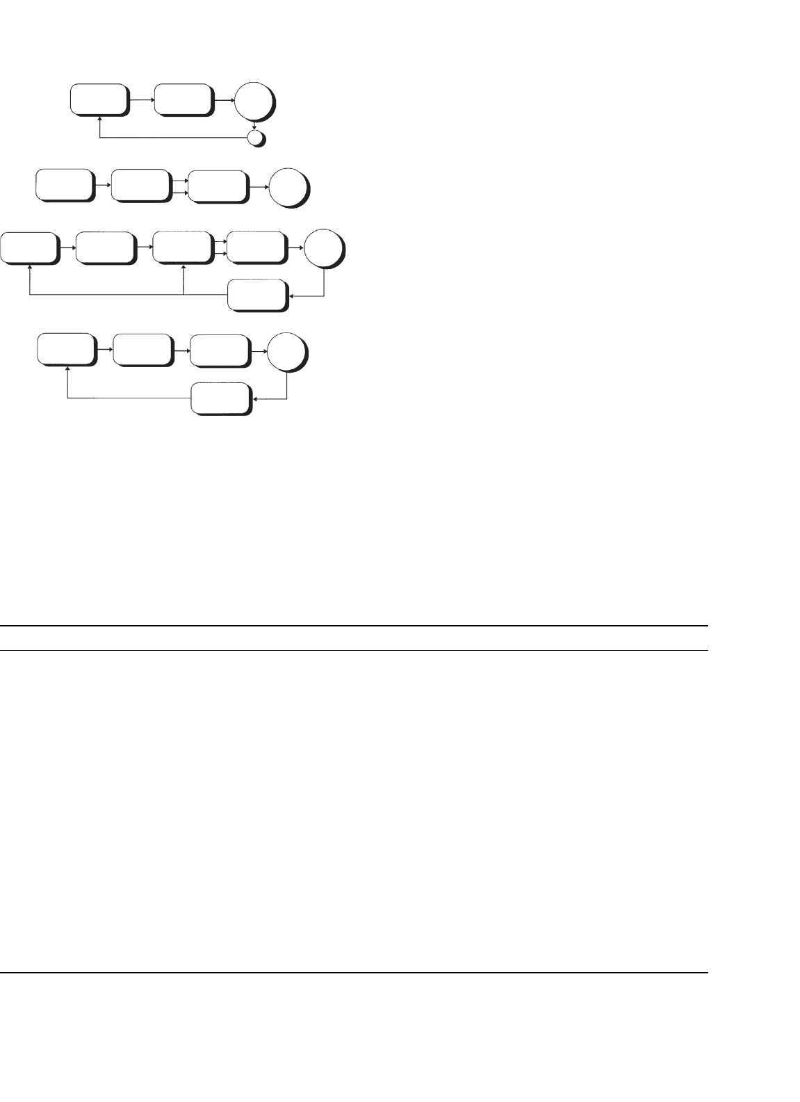
FIGURE 32.6 Electrical drive control techniques. (a) DC drive; (b)
frequency control (PWM scalar control); (c) flux vector control (field-
oriented control); and (d) direct torque control.
TABLE 32.15 Comparison between various control methods used in VSD
Drive type DC drive AC drive
Control method • Field-oriented • Frequency control • Flux vector control • Direct torque control
Features
• Field orientation via
mechanical commutator
• Controlling variables are
armature current and field
current
• Torque control is direct
• Typical response 10–20 ms
• Voltage and frequency
control
• Simulation of variable
speed drive using
modulator
• Flux provided with a
constant V/F ratio
• Open loop drive
• Load dictate torque level
• Typical torque dynamic
response 100 ms
• Field-oriented control –
similar to DC drive
• Motor electrical
characteristics are
modelled (observer)
• Closed loop drive
• Torque controlled
indirectly
• Typical torque dynamic
response 10–20 ms
• Use advance control
theory
• Controlled variables are
magnetizing flux and
motor control
• Typical torque dynamic
response is <5ms
Advantages
• Accurate and fast torque
control
• High dynamic speed
response
• Simple to control
• Low cost
• No feedback devices are
required
• Simple
• Good torque response
• Accurate speed control
• Full torque at zero speed
• Performance approaching
DC drive
• Simple
• No feedback requirements
• No need for an observe
Disadvantages
• Reduced motor reliability
• Regular maintenance
• Motor costly to purchase
• Needs encoder for
feedback
• Field orientation not used
• Motor status ignored
• Torque is not controllable
• Delaying modulator used
• Feedback is needed
• Costly
• Modulator is needed
environment, as all nodes are effectively running in
parallel.
Most modern VSDs are equipped with hardware and soft-
ware, which enable local and remote communication with
plant automated system via a Fieldbus system. The most pop-
ular Fieldbuses are Profibus, Interbus, Ctnet, Sercos, Worldfib,
and Devicenet.
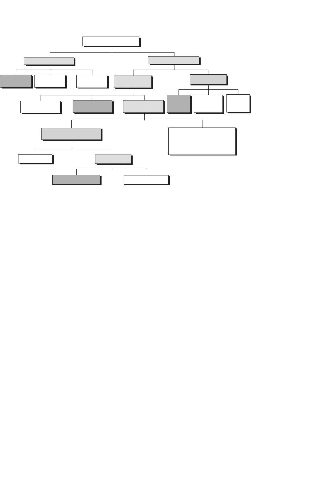
32.6.5 PWM Techniques
Different PWM techniques have been employed in PWM-VSD
converters. Figure 32.7 identifies the most commonly used
techniques.
32.6.6 Impact of PWM Waveform
32.6.6.1 PWM Voltage Waveform
Fast switching of IGBTs (typically <1 µs) results in high dV/dt,
typically 3–5 kV/µs, and possible voltage overshoot at turn
off which can last for a few microseconds. The fast rate of
rise/fall of voltage combined with high peak voltage at the turn
off, result in a premature failure of motors as well as EMC.
References [9–11] deal with the effect of PWM waveforms of
VSD.
The following is a brief summary of the effect of the
unfiltered waveforms.
32 Drives Types and Specifications 847
PWM Switching Strategies
Current-Controlled PWM
Voltage-Controlled PWM
Hysteresis
Current Control
Linear
Current Control
Preditive
Current Control
Fixed Switching
Frequency PWM
Random PWM
Random
Switching
Randomized
Pulse Position
Random
Switching
Frequency
Conventional PWM
Optimal & Harmonic
Elimination
Space Vector PWM
Natural Sampled
Modified Modulation Wave
(Sinusoidal with addition of third
Harmonic,trapezoidal, and other
waveforms)
Sinusoidal Modulation Wave
Regular Sampled
Asymmetric Modulation
Symmetric Modulation
•••
FIGURE 32.7 Classifications of PWM techniques.
32.6.6.2 Effect on Motor
• Premature insulation failure due to partial discharge as a
result of peak voltage, high dV/dt and high frequency.
• Motor shaft voltage, which forces current into the shaft
bearing, leading to early bearing failure.
• Motor stray capacitance (between windings and earthed
frame) leads to earth-current flow caused by high dV/dt.
• High dV/dt creates nonuniform distribution of voltage
across the winding, with high voltage-drop across the
first few turns and consequential failures.
• In a large motor, voltage differential on the frame is likely
to develop in spite of protective earthing of the motor.
More than one earthing point is needed.
32.6.6.3 Effect on Cables
• Voltage doubling effect at the rising/falling edges of
voltage waveform due to wave propagation in long
cables [9].
•
Earth-current flows in cable stray capacitance due to
dV/dt.
• Restriction on cable type used and earthing methods
employed.
• Cable type (armored, screen, multi-core).
• Likelihood of cross talk with other surrounding cables
running in parallel.
• For PWM drives, the cost of cabling is likely to be
significant due to special requirements of cables, and
termination methods employed.
32.6.6.4 Effect on EMC/Insulation/Earthing
• Inductive and capacitive couplings between live compo-
nents and earth result in common-mode and differential-
mode noise. This could lead to malfunctioning of nearby
sensitive equipment.
• The voltage to earth applied on drive components pul-
sates at the switching frequency, adding voltage stresses
(worst at low speeds, low modulation index). This poses
additional insulation requirements on main power com-
ponents (motor, cable, output filter, and transformer).
• A 4th wire may be required between the motor frame and
the converter virtual earth so that a low impedance path
is provided for the motor earth current.
•
Strict rules must be observed when cabling and earthing.
32.6.6.5 Motor Insulation
High peak voltages can be experienced at the motor terminals
especially when long cable is employed (10–100m depending
on the size of motor). This is usually caused by voltage dou-
bling phenomena of a transmission line with unequal line and
load impedance. Motor line voltage can reach twice the DC
link voltage with long cables.
Fast voltage rise times of 5000 V/µs can be measured at the
motor terminals. Under this condition the motor insulation
becomes stressed and can lead to a premature breakdown of a
standard motor insulation. When motor fails due to insulation
stress caused by high peak voltage and fast voltage rise times,
failure occurs in the first turn as phase-to-phase short or phase

848 Y. Shakweh
to stator short. The highest voltage is normally seen by the first
turn of the winding.
Standard motor capabilities, established by the National
Electric Manufacturers Association (NEMA) and expressed in
the MG-I standard (part 30), indicate that standard NEMA
type B motors can withstand 1000 V peak at a minimum rise
time of 2 µs (500 V/µs). Reference [10] describes the effect of
PWM inverter waveform on motor insulation in more detail.
Partial Discharge
The phenomena which starts deterioration of the motor insu-
lation is called Partial Discharge (PD). When electric stresses
in insulation voids exceed the breakdown voltage of the air, a
partial discharge occurs. Successive PDs destroy the insulation
slowly.
Voltage Strength between Phase to Phase and
Phase to Frame
Both NEMA and IEC are proposing: (a) maximum 1000 V at
rise time less than 2 µs and (b) a maximum rate of rise of
500 V/µs. It is believed that low voltage standard motors can
withstand a lot larger voltage stresses than specified by NEMA
and IEC, possibly up to 1300 V, almost regardless of the rise
time.
Voltage Strength between Turn to Turn
In low voltage AC motors, the conductor insulation is designed
for 245 V RMS (350 V peak). The insulation strength is
however higher depending on the impregnation method.
32.6.6.6 Bearing Current
Bearing current and shaft voltages under 50/60 Hz sine-
wave operation has been recognized since 1924. The bear-
ing impedance characteristics largely determine the resulting
bearing current that will flow for a given shaft voltage [11].
The rotating machines have three basic sources of shaft
voltage. These are:
• Electromagnetic induction from the stator winding to the
rotor shaft (due to small asymmetries of the magnetic
field in the air gap that is inherent in a practical machine
design. The design limit is <1 V RMS.
• Electrostatic coupled from internal sources: such a volt-
age in motors where rotor charge accumulation may
occur (belt-driven coupling, ionized air passing over
rotor fan blades).
• Electrostatic coupled from external sources such as PWM
inverter. The presence of high dV/dt across the stator
neutral to frame ground causes a portion of the voltage
to ground due to capacitor divider action. The presence
of PWM related voltage components is undesirable and
lead to a premature bearing failure.
• The fundamental cause of the shaft voltage is magnetic
asymmetry between the stator and the rotor or possi-
bly a phase shift of the motor voltage waveform. System
ground may also contribute to this condition through
unbalance system voltage.
• NEMA-500 recommends the consideration of insulated
bearing for motor frame of certain sizes.
32.6.6.7 EMC
The main sources of electromagnetic emission of PWM-VSI
drives are described in [12] as follows:
AC/DC Converter: Supply harmonics caused by supply
bridge rectifier (100 Hz–2.5 kHz): As already explained the
input bridge circuit with a SCR or diode bridge is a source
of supply harmonics in the input current.
DC/AC Inverter: Harmonics caused by the switching of the
inverter bridge (3 kHz–20 MHz): the inverter bridge uses fast
switching devices to create PWM voltage output. The inverter
is a source of a wide band of frequencies, typically extending
from the basic switching frequency (usually several kilohertz)
to the radio high-frequency bands at 20 MHz. The radio fre-
quency current spreads out into both the supply and motor
connections. An EMC filter is often used to limit spread of
high frequency harmonics into the supply.
Control Electronics: The control circuit employs a micro-
processor with clock frequency of several megahertz, typically
20 MHz. The clock wave produces frequencies, which are
multiple of 20 MHz up to 300 MHz.
32.6.7 Techniques Used to Reduce the Effect of
PMP Voltage Waveform
32.6.7.1 Output Line Reactor
A reactor increases the rise time but the benefit of its
connection may be negated as follows:
• Beneficial connection if cable length is short enough for
reflections to be superimposed within rise time, i.e. if rise
time is increased beyond critical value of cable length.
• Harmful connection if cable length is too long, the reactor
may have negligible effect on peak voltage (theoretically
its presence is insignificant in this case) or ringing period
but it will increase the duration of each overshoot, thus
increasing the probability of partial discharge.
Adding a series line reactor between the motor and inverter
is not as simple as illustrated above because the reactor adds
or adjusts other resonant modes where the reactor rings
with lumped capacitance’s. These resonant modes are pure
transmission line modes and can double voltage. Some line
inductance helps short circuit protection. If earth current is
limited by other means, then the coupled reactors may be
helpful.

32 Drives Types and Specifications 849
TABLE 32.16 An overview of techniques used as a counter measure to EMI
Effect Frequency range (f) Counter measure
At source At load
Mains ≤100 Hz • Avoid circulating currents • Balanced signal circuits
• Avoid earth loops in signal paths
• Screening (electric field only)
Mains harmonics 100 < f ≤ 2.5 kHz
• Line and/or DC link reactor on rectifiers.
• Higher pulse number rectifier (e.g. 12, 18, or 24)
• Low impedance supply
•
Harmonic filters
• Balanced signal circuits
• Avoid earth loops in signal paths
• Filtering
Intermediate 2.5 < f ≤ 150 kHz
• Filters •
Filtering
• Screening
•
Balanced signal circuits
Low-frequency 150 kHz < f ≤ 30 MHz
• Filters – one per apparatus
• Cable screening
• Filtering
• Screening
High frequency 30 MHz < f ≤ 1 GHz
• Screening
• Internal filtering
• Screening
32.6.7.2 Sine-wave Filter
This mechanism filters the PWM carrier frequency; thus the
converter output voltages are sinusoidal. This type of filter is
best suited for low performance drives and/or retrofit applica-
tions (old or standard motors). Reference [13] and Table 32.17
illustrates the filtering options for high power VSDs.
Employing a filter at the inverter output has some practical
consequences:
• Cost and weight of filter
• Filter power losses, voltage drop
• A small derating of power switches due to circulating
current between filter L, C, and DC link capacitor
TABLE 32.17 Filtering options for PWM-VSI drives, Reference [13]
Option No filter dV/dt filter Sine-wave filter
Motor dV/dt High Acceptable Low
Motor insulation Must be
increased
Normal Normal
EMC ground noise Very high Low Very low
PWM carrier at
motor
100% 100% Very low
Motor audible noise Higher Decreased a little Minimum
Motor derating Approx. 13% Approx. 3% 0%
Torque response Fast Fast Suits most
applications
Motor cost Typically
+10% cost
Normally no
extra cost
No extra cost
Conclusions Impractical Suitable only for
high dynamic
torque
response
Best choice for
most drives
•
Reduced torque response due to time delay in the filter,
sine-wave type
• Potential oscillations which have to be electronically
dampened
• Potential induction motor self excitation
32.6.7.3 PWM (dV/dt) Filter
This reduces the dV/dt seen by the motor to a level, which
does not compromise the motor or EMC. It is ideal for high
performance drives with custom-built motors.
32.6.7.4 RC Filter at Motor Terminals
A simple RC network is used at the motor terminal; the
capacitor would represent a short circuit for the high fre-
quency components (sharp dV/dt). Wave reflection will not
happen if the resistor value is similar to the cable character-
istic impedance. Resistor losses are generally small, as current
flow will only occur at the rising and falling edges of the PWM
waveform.
32.6.7.5 Common Mode Reactor
The presence of capacitive current due to the high dV/dt can be
improved by employing a common mode reactor. It is well-
established that such a choke is not effective to reduce the
RMS and mean values of the leakage current, but only effective
to reduce the peak value. The presence of such a choke in
the circuit, increases the inductance and resistance of the zero
sequence impedance.

850 Y. Shakweh
TABLE 32.18 Types of supply front-end bridges of PWM-VSI drives
Type Power device Motor speed
reversal
Regenerative capability Regenerative with
AC supply loss
Comment
I Diode Yes No No • Good power factor across speed range
• Needs pre-charge circuit
• Lack of protection
II Diode Yes Dissipative Yes
• Ditto
III SCR Yes No No
• Power factor is function of speed
• Fully controlled DC link
• Phase back when (a) supply voltage rises,
(b) fault on DC bus side
• Needs gate drivers for SCRs
IV SCR Yes Dissipative Yes
• Ditto
V SCR Yes Regenerative into supply No
• Ditto
VI Forced
commutated
devices (e.g.
IGBT/IGCT)
Yes Regenerative into supply No
• Can operate with controlled power factor (unity,
lagging, leading)
• High frequency harmonics
• DC link voltage higher than the crest of the
supply voltage
• Fully controlled DC link, even during a supply
dip
• Output voltage equals to input voltage
• Requires a pre-charge circuit
32.6.8 Supply Front-end for PWM-VSI Drives
There are many types of PWM voltage source drive depend-
ing on the supply front-end type and regenerative technique
employed (Table 32.18)
(i) PWM-VSI with a diode supply front-end
(ii) As above, but with a dynamic brake chopper
(iii) Fully controlled thyristor front-end
(iv) As above but with a dynamic brake chopper
(v) Fully controlled anti-parallel thyristor supply bridge
(vi) PWM supply front-end
The use of a higher pulse number than 6-pulse would neces-
sitate the use of a supply transformer. This is always considered
to be an unnecessary “evil” because of additional cost, losses,
and the need for extra space to accommodate this component.
For MV applications, this is considered to be a necessity for
isolation and protection.
32.6.8.1 Regenerative Braking
Several techniques are usually used for regenerative braking.
A simple diode front-end supply bridge will operate in two
quadrants (positive and negative speeds). There is no regen-
erative power capability as any regeneration of power would
result in an increase in the DC link voltage, and the drive will
trip on over-voltage.
If a small amount of regeneration is required, during stop-
ping, or speed reversal, then a dynamic brake chopper may
be used. This is a simple chopper with a dynamic brake
resistor. The size of the resistor is very much dependent on
the regenerative brake energy, its magnitude, and repetition
rate.
Full power regeneration is possible by employing a fully
controlled anti-parallel thyristor front-end. This is similar to
that used on DC drives or cyclo-converters.
A more modern approach is to use pulse converter front-
end (fully controlled bridge). This is a four-quadrant converter
with the ability to control the power factor and the DC link.
Such an option necessitates the use of a pre-charge circuit for
the DC link, and smoothing inductance on the AC side.
For fully regenerative drives, the supply needs to be
receptive.
By using a PWM rectifier as a primary converter in this com-
posite structure both the problems of regeneration and line
current distortion are successfully solved – with the penalty
of having a much more complicated converter structure and
control system.
With the modern PWM-VSI VSD controller, the supply
bridge can be fully controlled. Such an option offers the
following benefits:
• Fully regenerative drive
• Unity power factor all time
• Sine wave input voltage and current
• Can operate with controlled power factor (e.g. leading
power factor)
•
Can operate as an active filter while supplying power
to the load. Possible elimination of low order supply
harmonics (5th & 7th)
• Output voltage equals the input voltage

32 Drives Types and Specifications 851
TABLE 32.19 Application analysis of VSDs
Industry Current drive Preferences Applications
topology
Power generation Direct On Line
(DOL)
• 6.6–11 kV Boiler feed pump, start-up converter, coal mills
Soft start
CSI
Petrochemical LCI
DOL
CSI
• Air-cooled, stand-alone.
•
Induction motors up to 10 MW
• Synchronous above 10 MW
Petrochemical and derivatives, gas liquefaction, pipelines and
storage, oil on/off shore and pipelines
Mining Cyclo-converters
• Low maintenance
• Reliability
• Low power supply distortion
Mine winders, conveyor belts, coal mills, ventilation fans,
underground machinery
Stand-alone and
process industries
• Low cost
• Efficiency
• Ease of repair and maintenance
Water and sewage pumps, wind mills, material handling
(extruders), test benches, paper and plastic machines
Metals Mill drives –
cyclo-
converters
• Air-cooled
•
High dynamic performance
• Low maintenance motor
Hot mills, medium section mills, finishing section mills, cold
mills
Marine LCI cyclo-
converters
• Small size
•
Low maintenance
• Water-cooled
Warships, drilling vessels (mono-hulls), chemical tankers
shuttle tankers, cruise liners, icebreakers, semi-submersibles,
fishing vessels, cable layers, floating exploration rigs, ferries,
research vessels, container vessels
32.7 Applications
32.7.1 VSD Applications
Table 32.19 summarizes main industries and applications.
Present solution of drives, and electric drive application
examples from various industries have been described in this
section.
32.7.2 Applications by Industry
32.7.2.1 Deep Mining
Reference [14] lists various high-power MV VSI inverter drive
applications for the mining industry. In deep mine con-
veyor belt applications a PWM-VSI drive offers significant
advantages over other conventional alternatives. The follow-
ing benefits have been identified for deep mine conveyor belts
applications:
•
Improved drive starting and stopping
•
Improved reliability
• Matching belt speed to production
• Easier belt inspection
• Reduced belt wear, increased belt life
• Lower specification belt material may be used
• Low speed running to reduce coal removal by windage
• Manpower saving – less coal spillage
• Unity power factor with low harmonic content
• Reduced AC supplies disturbances
For hoist applications, the PWM-VSI drives can also be
used to replace DC and cyclo-converter drives for Mine Hoist
applications. The benefits are:
• Improved drive control, with 100% continuous stall
torque available with induction motors
• Reduced AC supplies disturbances
•
Very unlikely to need reactive MVAR correction even at
high ratings
• Improved immunity to AC supplies dips
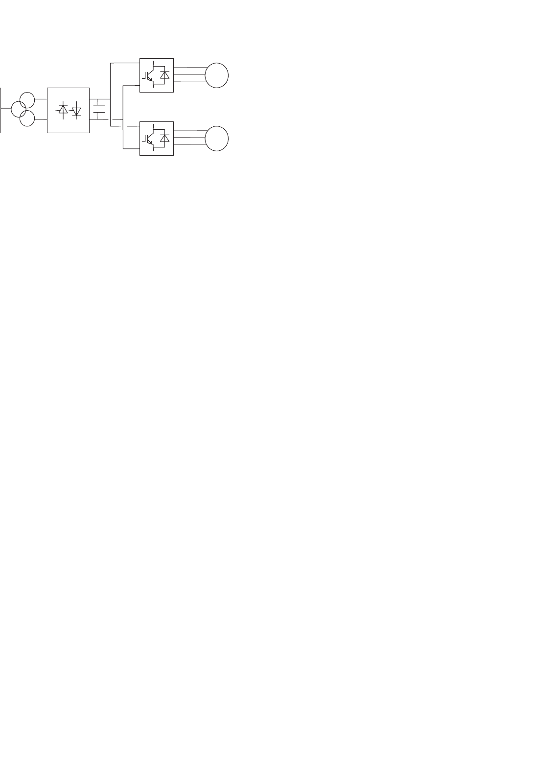
The use of electrically coupled Mine Hoist systems have
many advantages especially for deep mines and set to become
an essential feature of many new mine shaft systems. The
circuit is shown in Fig. 32.8.
The power flows naturally from the motor 1 to motor 2 such
that at the point of balance the AC supply current is virtually
zero and at near unity power factor.
This technology is the natural successor to the DC electri-
cally coupled winders and totally solves the poor AC power
factor that would result if twin drive cyclo motors were used.
32.7.2.2 Industrial Processes
In this industry, there are a number of viable drive solu-
tions available for the major market power ranges, from LCIs
852 Y. Shakweh
Motor 1
Motor 2
12 pulse supply converter
FIGURE 32.8 PWM-VSI electrically coupled Mine Hoist drive.
to FCI. However, there is a developing market for MV variable
speed drives. The PWM-VSI using new high power IGBTs or
IGCTs appear to be the best solution for the future. Benefits
include better power factor, no limit on frequency, and higher
voltages.
PWM-VSI converter cost is likely to be higher than equiva-
lent other well-established technologies (e.g. LCI). Hence, the
flexibility in choice of motors, and improved control must be
exploited. The advantage of offering a MV solution may prove
significant. Possible means of reducing motor costs are:
1. Higher frequencies are achievable, allowing the use of
high-speed motors and gearboxes
2. Higher pole number machines can be used, giving a
cost saving
3. Better power factor over the speed range giving power
supply saving
4. Induction motors with rotors adapted for use with
VSDs can be used with resultant cost savings over
standard DOL, fixed speed motors
5. Higher voltages, smaller conductors
6. However, at low powers the relative cost of the
machines is less significant versus the cost of the con-
verters. Hence, the viability of this technology in this
market requires close examination
The cyclo-converter drive with a synchronous motor is
used when four-quadrant operation is required. Particularly
for high power rating with high torque at low speed and at
standstill but with a rather low maximum speed are drive
requirements. Gear-less cement mill drives were the first appli-
cations of cyclo-converters. The mill tube is driven from
low-speed wraparound motor with a high number of poles.
32.7.2.3 Metal Industry
The majority of installed hot mill drives are cyclo-converters. A
few LCI drives have been used, but applications are limited for
such technology on Mill Main Drives. Most early generation
plants are equipped with DC drives. The trend is to replace
DC with AC.
Direct current drive applications were universally used in
the first generation of Rolling Mills. The market for New Mills
requiring this technology is declining as the Steel Industry
moves to AC as a preference. On early generation Mills where
motors are retained, DC drives are likely to be required. Cus-
tomers in their enquiries, some requesting AC alternatives, are
still requesting DC drive solutions.
DC drives are probably still the most economic for the
power range 750–1500 kW. The number of manufacturers
however, producing DC motors, is declining, particularly in
the case of large DC motor manufacture. The lower price of
DC solutions is offset by the advantage of use of AC motors
in AC solutions, making AC the more popular choice.
Current source inverter LCI can be applied to Roughing
stands of Rod & Bar Mills. Technical limitations include
the risk of torque pulsation and a minimum drive output
frequency of 8 Hz.
Cyclo-converter is the solution most often used. However,
it is relatively expensive compared to alternative technology.
Major cost penalties arise from supply transformers, cabling
and bridge configuration. In some cases, active power sup-
ply compensation equipment may be required, taking the
costs even higher. Cyclo-converter solutions will still be cost-
effective for medium to high power, low speed, low frequency
(say below 21 Hz maximum operating frequency) applications.
This would include hot reversing mills, with direct drive, for
the primary rolling processes; albeit a declining application
area, and possibly for direct drive, low speed, high torque
roller table applications. Technical limitations include limited
output frequency (typically 29 Hz for 12-pulse, at 60 Hz sup-
plies), which can necessitate the use of 2-pole motors to reach
application speeds.
The high power PWM-VSI using new power devices
(IGBT/IGCT) appears to be the best solution for the future.
Benefits include better power factor, no limit on frequency,
and higher voltages. Potentially either the 2-level or the
multi-level solution will meet the market requirements.
In some applications, like coilers/uncoilers, the system is
composed of several drives, which have different power cycles,
when some drives are furnishing power, other are braking.
A common DC bus system will allow that the energy fed
from drives operating in the regenerative braking mode will
be utilized by other drives connected to the same DC bus, but
operating in the motoring mode. The supply bridge, i.e. recti-
fier, feeding the DC bus system, will only be rated for the total
system power.
The benefits of the DC bus systems include:
• Good operating power factor
• Low harmonics (lowest when using 12-pulse, or 18-pulse
front ends)
• Possibility of energy transfer on the common DC link
solutions (reducing front-end converter and transformer
sizes with attendant energy saving, possibility of using
kinetic energy to allow controlled stopping)

32 Drives Types and Specifications 853
32.7.2.4 Marine and Offshore
Drive powers are commonly in the range of 0.75–5.8 W for
thrusters, and 6–24 MW for propulsion. The evolution in the
commercial market is towards powers from 1 to 10 MW for
propulsion. Higher powers are required for naval applications
with package drive efficiency better than 96%.
The PWM inverters at these powers would allow the use
of induction machines, rather than the more expensive syn-
chronous alternatives required for LCI drive. This could give
savings in the price of the motor.
Current source inverter drive LCI is used for all applications
except for icebreakers where cyclo-converter drives are used.
The PWM (voltage source) inverter using new force commu-
tated driven appears to be the best solution for the future.
Benefits include better power factor, no limit on frequency,
and higher voltages. Many icebreakers and some other ships
are equipped with diesel generator fed cyclo-converter syn-
chronous motors with power ratings up to about 20 MW per
unit.
32.7.3 Examples of Modern VSD Systems
32.7.3.1 Integrated Power System for All Electric Ship
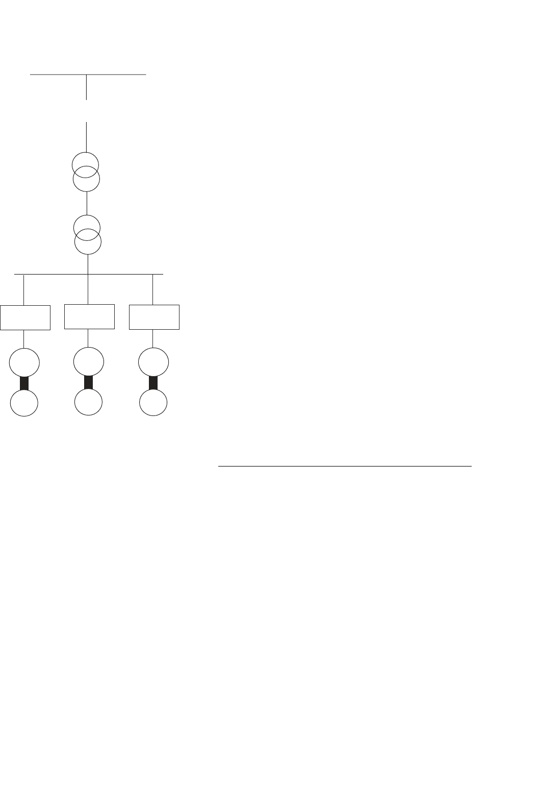
This is a full-scale main propulsion drive for the US Navy [15].
It consists of a main propulsion 19 MW induction motor drive
system. The power converter consists of three 6-pulse recti-
fier stages, three 6 kV DC links and 15 IGBT-based H-bridges
feeding a 15-phase induction motor (Fig. 32.9).
This drive demonstrates the potential of modern power elec-
tronics over more traditional solutions such as cyclo-converter
H
LC
H
LC
H
LC
H
LC
H
LC
Passive 5th
harmonic
filter
15 phase, 19MW
induction motor
A single dc bus, 6kV
DC, feeding 5xH
bridges.
21MW
generator
IMG
6 pulse diode
bridge
FIGURE 32.9 Schematic diagram of the IPS drive system [15].
and LCI. The volumetric power density of the new converter is
reported to be 905 kW/m
3
, compared to 455 kW/m
3
for cyclo
and 313 kW/m
3
for LCI.
32.7.3.2 Sub-sea Separation and Injection System
This is a full-scale pilot plant developed to increase recov-
ery and improve the economics of offshore oil and gas fields.
The system comprises several VSD units, typically 500 kW oil
pump. 1 MW multi-phase booster and 1–2.5 MW water injec-
tion drive unit and such a system is called “SUBSIS” [16]. The
main task for such a system is to separate the bulk water from
the well stream and treat it either for discharge into the sea or
re-injection into the reservoir.
This system employs sub-sea based rotating machinery for
pumping, boosting, and compression. The sub-sea Electri-
cal Power Distribution System (SEPDIS) is an innovative
and cost-effective sub-sea processing (Fig. 32.10). The pump
motors are mounted in a pressurized vessel and positioned on
the seabed. Reference [16] identifies the benefits of sub-sea
drives as follows:
•
3–6% increase in oil and gas recovery
• improved pipeline transportation conditions by remov-
ing water from the well stream
• reduced environmental impact due to lower energy con-
sumption and reduction in chemicals used to inhibit
corrosion
• reduced size and cost of new platforms
• cost-effective development of marginal fuels through
reuse of existing infrastructure
854 Y. Shakweh
HV AC bus
ACCB
Step up
AC/AC
M
X
AC/AC
M
X
AC/AC
M
X
Oil pump
500kW
Oil pump
1MW
Oil pump
1-2.5MW
Long cable
Step down
X
FIGURE 32.10 Schematic diagram of SEPDIS.
32.7.3.3 Shaft-generator for Marine Application
During cruising at sea, up to 3.5 MW of electric power is
extracted from the ship’s main diesel engine/propeller shaft
(90,000 hp per ship) via a salient pole shaft generator, which is
fitted to the main propeller shaft. The converter output voltage
(set at 60 Hz) is stepped up to 6.6 kV [17].
The converter is based on 24-pulse converter (LCI) tech-
nology, which is traditionally used as main ship propulsion.
The shaft generator output frequency varied between 14 and
25.7 Hz, 6-phase generator and the output stage is configured
as 24-pulse, via a step-up transformer. At the output a passive
LC filter is employed, with a synchronous condenser, started
by a pony motor.
This type of application is likely to significantly benefit from
the higher volumetric power density of the PWM VSI with
fully controlled front-end. Such a system will eliminate the
need for a passive filter at the output stage, and use a standard
3-phase generator.
The same technology is also applicable to high-speed gener-
ators and windmill energy. The ability of the active front-end
to sustain fixed DC link voltage over a relatively wide shaft
speed range, results in a very good control of the output
voltage, irrespective of the shaft speed.
In wind power plants the optimal efficiency of the wind tur-
bine depends on the speed when the wind conditions change.
It is, therefore, advantageous to vary the speed of the generator
and link it via a frequency converter to the AC system.
For high-speed generators, driven by diesel engine or gas
turbine, the fully controlled converters enable direct power
conversion from AC high frequency (hundreds of Hz) to fixed
power frequency (50/60) Hz fixed output voltage. The mag-
nitude of the output voltage is kept constant irrespective of
speed variation of the generator.
32.7.3.4 Linear Motor Drive for Roller Coaster
This drive involves a fully regenerative PWM VSI. The supply
front-end is made of anti-parallel thyristors front-end while
the machine-bridge is based on PWM IGBT VSI. The Escape’
has been developed for Six Flags California at Magic Moun-
tain. The inverter output frequency is 0–230 Hz, and 525 V
AC RMS. The power rating is 1.8 MW. The duty cycle is
1.8 MW for 7 seconds, followed by 16 seconds at zero power,
and 1.3 MW for 5 seconds, and a stop period of 32 seconds.
This ride involves acceleration at 4.5 g, speed and free-fall
(6.5 seconds of weightlessness, during which a height of 415 ft
is achieved [18]).
The same concept employed in this application could be
used for aeroplane launcher on aircraft carriers, instead of the
conventional catapult.
32.8 Summary
The benefits of VSD are there to be quantified, and energy
saving has been the prime reason for employing a VSD
in stand-alone drive applications. Other benefits such as
improved process control or increase life expectancy are often
difficult to quantify in real terms.
There is a large selection of VSD systems to meet a wide
range of applications. In the low and medium power, the
induction motor and PWM-VSI are supreme. At higher power
ratings, MV PWM-VSIs are gaining popularity, but LCI and
cyclo-converter drives would remain key technologies with
very high power applications.
Modern drives are becoming more available at competitive
prices with good reliability record. However, there are con-
cerns with regard to the impact of fast switching on the motor
and the environment.
To ensure successful implementation of a VSD system,
both the supplier and end-users need to work in partnership.
Ideally, one competent supplier should supply the full drive
package, with some after sale service support. Understanding
the nature of the load plays an important role in specifying