Power electronic handbook
Подождите немного. Документ загружается.

886 M. F. Rahman et al.
in the rotor and by having three-phase windings in the stator
that are supplied from an inverter.
The arrangement just mentioned is very similar to a con-
ventional synchronous motor. This is particularly so when the
stator windings and the rotor mmf are sinusoidally distributed.
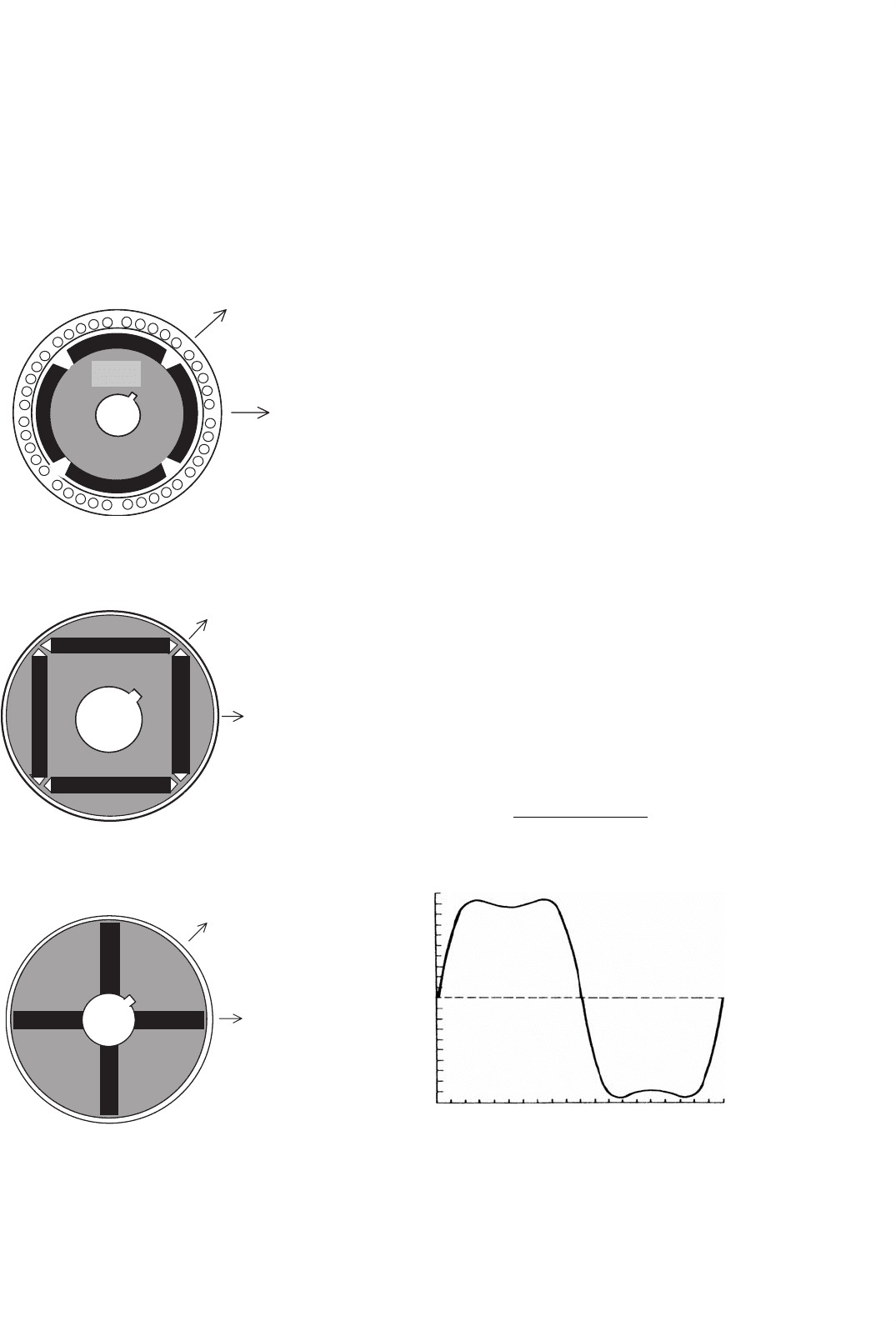
Several rotor configurations of the PM synchronous motor
have been developed, of which the important ones are
indicated in Figs. 33.45–33.47.
rotor
q-axis
d-axis
FIGURE 33.45 Schematic of the cross section of a surface-magnet
synchronous motor.
q -axis
d -axis
FIGURE 33.46 Schematic of the rotor cross section of an interior-
magnet motor.
d -axis
q-axis
FIGURE 33.47 Schematic of the rotor cross section of a circumferential-
magnet motor.
33.5.2 The Surface-magnet Synchronous Motor
The surface-magnet motor comes with the rotor magnets
glued onto the surface of the rotor. An additional stainless steel
(i.e. nonmagnetic) cylindrical shell may be used to cover the
rotor in order to keep the magnets in place against centrifugal
force in high-speed applications. Since the relative permeabil-
ity of the magnetic material is very close to unity, the effective
airgap is uniform and large. The airgap is normally about
8 mm. Consequently, the synchronous inductances along the
rotor d- and q-axes, as indicated in Fig. 33.45, are equal and
small (i.e. L
d
= L
q
= L
s
). The armature reaction in this type
of motor is small.
The three-phase winding in the stator has sinusoidal dis-
tributed windings. In another form, the motor may have
trapezoidal distributed winding, and the rotor mmf is also
uniformly distributed. Such a motor, often called a brushless
dc (BLDC) motor because of its similarity to the inside-out
conventional brushed PM DC motor, develops a trapezoidal
back-emf waveform as indicated in Fig. 33.48, when it is driven
at a constant speed. The back-emf waveforms have flat tops
for nearly 120
◦
in each half-cycle followed by 60
◦
of transition
from positive to negative polarity of voltage and vice versa.
These motors are very suitable for variable-speed applications
such as spindle drives in machine-tool and disk drives.
33.5.2.1 Control of the Trapezoidal-wave Motor
Neglecting higher-order harmonic terms, the back-emf in the
motor phases may be as indicated in Fig. 33.49. Each back-
emf has a constant amplitude (or flat top) for 120
◦
(electrical)
followed by 60
◦
of transition in each half-cycle. The developed
torque at any instant is given by
T =
e
an
i
a
+e
bn
i
b
+e
cn
i
c
ω
Nm (33.71)
36
18
EMF, V
0
−18
−36
0 90 180
θ, degree
270 360
FIGURE 33.48 Back-emf of a trapezoidal waveform motor.
33 Motor Drives 887
1261
23 34
4534
1261
56
34
34
12
23
56
45
12
56 56
23
61
23
61
e
a
e
b
e
c
i
a
i
b
i
c
60°
60° 60°
60°
120°
120°
120°
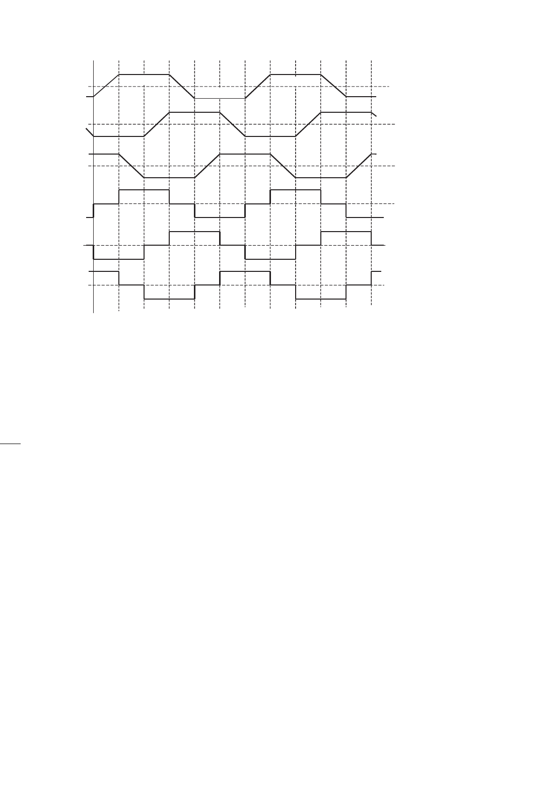
FIGURE 33.49 Back-emf and current waveforms and on-states of transistor switches in the trapezoidal-waveform motor.
It is readily seen that the ideal current waveform in each
phase needs to be a quasi-square waveform of 120
◦
of con-
duction angle in each half-cycle. The conduction of current in
each phase winding coincides with the flat part of the back-emf
waveforms, which guarantees that the developed torque, i.e.
c
x=a
e
xn
·i
xn
ω
r
, is constant or ripple-free at all times. With such
quasi-square current waveforms, a simple set of six opto-
couplers or Hall-effect sensors would be required to drive the
six inverter switches indicated in Fig. 33.36. The output cur-
rent waveforms for the three-phase inverter and the switching
devices that conduct during the six switching intervals per
cycle are also indicated in Fig. 33.49. Since only six discrete
outputs per electrical cycle are required from the rotor posi-
tion sensors, the requirement of a high-resolution position
sensor is dispensed with. Continuous current control for each
phase of the motor, by hysteresis or PWM control, to regulate
the amplitude of the motor current in each phase is normally
employed. The operation of the BLDC motor drive is described
in detail in Section 33.6.
Even though careful electromagnetic design is employed in
order to have perfect trapezoidal back-emf waveforms as indi-
cated in Fig. 33.49, the back-emf waveforms in a practical
brushless dc motor exhibit some harmonics, as indicated in
Fig. 33.48. If ripples in the back-emf waveforms are signif-
icant, then torque ripples will also exist when the motor is
driven with quasi-square phase current waveforms. These rip-
ples may become troublesome when the motor is operated at
low speed, when the motor load inertia may not filter out the
torque ripples adequately.
A second source of torque ripple in the permanent-magnet
brushless dc (PM BLDC) motor is from the commutation of
current in the inverter. Since the actual phase currents cannot
have the abrupt rise and fall times as indicated in Fig. 33.49,
torque spikes, one for each switching, may exist.
Even though the PM BLDC motor does not have sinusoidal
back-emf and inductance variations with rotor angle, the anal-
ysis of Section 33.4 in terms of the fundamental quantities
will often suffice. The switching of the inverter using the six
rotor-position sensors guarantees that the current waveform in
each phase always remains in synchronism with the back-emf
of the respective phase. Since the quasi-square phase current
waveform in each phase coincides with the flat part of the
back-emf waveform of the same phase, the angle γ is clearly
zero for such operation. Thus, considering fundamental quan-
tities, the motor back-emf and the torque characteristics can
be expressed by
E = K
E
ω V (33.72)
T = K
T
I cos γ = K
T
I Nm (33.73)
where K
E
and K
T
are equal in consistent units. Note that E
and I are now RMS values of the fundamental components of
these quantities.
888 M. F. Rahman et al.
33.5.2.2 Sensorless Operation of the PM BLDC Motor
In spindle and other variable-speed drive applications, where
the lowest speed of operation is not less than a few hundred
revs/min, it may be possible to obtain the switching signals for
the inverter from the motor back-emf, thus dispensing with
rotor-position sensors. The method consists of integrating the
back-emf waveforms, which are the same as the applied phase
voltage if the other voltage drops are neglected, and comparing
the integrated outputs with a fixed reference. These compara-
tor outputs determine the switching signals for inverter. It
may be noted that the amplitude of the back-emf waveforms
is proportional to the operating speed, so that the frequency
of the comparator outputs increases automatically with speed.
In other words, the angle γ and the current waveform rel-
ative to the back-emf waveform in each phase remains the
same regardless of the operating speed. Integrated circuits are
available from several suppliers, that perform this task of sen-
sorless BLDC operation satisfactorily, covering a reasonable
speed range.
33.5.3 The PM Sinewave Motor
The PM sinewave motor, which may also have magnets on the
rotor surface or buried inside the rotor (as in the interior-
magnet motor of Fig. 33.46), has sinusoidally distributed
windings. The airgap flux distribution produced by the rotor
magnets is also sinusoidal, arranged through magnet shaping.
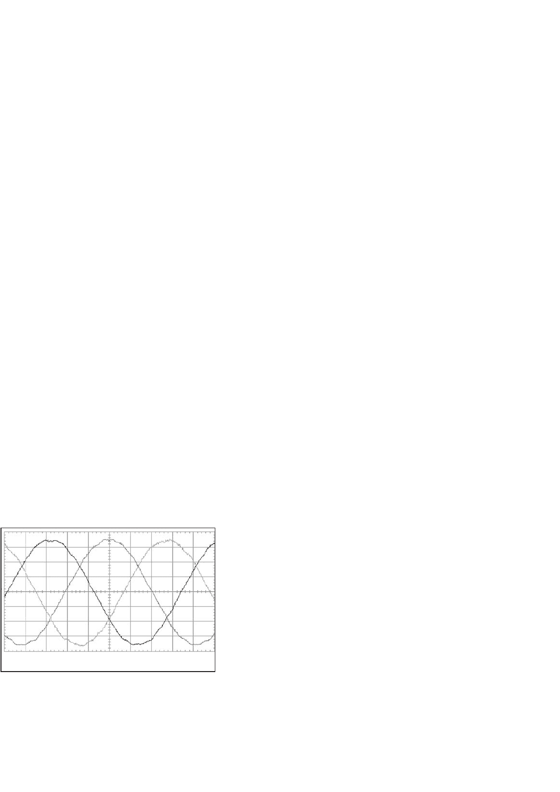
Consequently, the back-emf waveform of each phase is also
a sinusoidal waveform, as indicated in Fig. 33.50, when the
motor is driven at a constant speed.
It should be noted, however, that with magnets mounted
on the rotor surface, the effective airgap is large and uniform
so that L
d
= L
q
= L
s
. Because of the large equivalent air-
gap, these inductances are also small, and consequently, the
armature reaction is small. As a result, this motor essentially
operates with fixed excitation, and there is hardly any scope
100 V/div 5 ms/div
FIGURE 33.50 Back-emf waveforms of a sinewave PM motor.
Speed = 1815 rev/min.
for altering the operating power factor or the rotor mmf, once
the motor and its drive voltage and current ratings have been
selected.
The PM sinewave interior-magnet motor, which comes with
magnets buried inside the rotor as indicated in Figs. 33.46 and
33.47, has an easier magnetization path along the rotor q-axis,
so that L
q
> L
d
. The small airgap implies that the inductances
L
d
and L
q
may not be small, and hence may allow considerable
scope for field weakening.
If the sinewave motor is supplied from an SPWM inverter,
the analyses and vector diagrams of this motor are not different
from those in Section 33.4 for the nonsalient-pole and salient-
pole synchronous motor drives. The surface-magnet motor is
more akin to the nonsalient-pole motor, since L
d
= L
q
= L
s
,
whereas the interior-magnet motor is more akin to the salient-
pole motor because of the d- and q-axes inductances being
unequal. Thus, the equations in Section 33.4 will apply equally
well for this motor, both in the steady state and dynamically
and for both voltage- and current-source supply.
33.5.3.1 Control of the PM Sinewave Motor
The sinusoidal back-emf waveforms imply that the three-phase
motor must be supplied with a sinusoidal three-phase currents
if a dc-motor-like (or vector-control-like) torque characteristic
is desired, as was found in Section 33.4. For such operation, the
phase currents must also be synchronized with the respective
phase back-emf waveforms, in other words, with the rotor dq-
reference frame. This implies the operation with a specified γ
angle. Two implementations are possible.
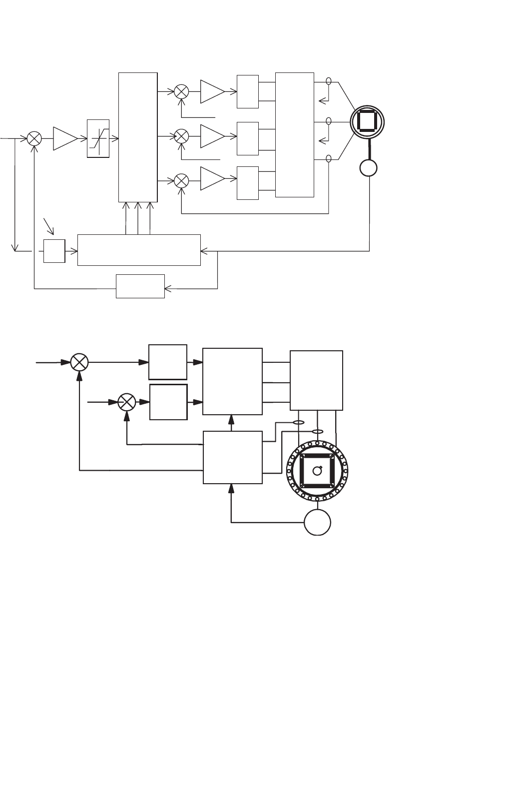
In one scheme, the stator currents are regulated in the stator
reference frame and the stator current references are produced
with reference to the rotor position, as indicated in Fig. 33.51.
The rotor position θ is continuously sensed and used to pro-
duce three sinusoidal current references of unit amplitude.
The phase angle γ of the references relative to the respec-
tive back-emf waveforms is usually derived from the speed
controller, which defines the field-weakening regime of the
drive. The operating power factor of the drive may also be
addressed using the γ angle control, as explained in Section
33.4.5. The amplitudes of these references are then multiplied
by the error of the speed controller in order to produce the
desired torque reference. In this way, both the RMS value I
of the phase current and its angle γ with respect to E
f
can be
adjusted independently (which is equivalent to independent
dq-axes current control). Three PWM current controllers are
indicated, but two suffice for a balanced motor. Other types of
current controllers, such as hysteresis controllers, may also be
used.
In the second scheme, the motor currents are first trans-
formed into the rotor dq-reference frame using continuous
rotor position feedback and the measured rotor d- and q-
axes currents are then regulated in the rotor reference frame,
as indicated in Fig. 33.52. The main advantage of regulating
33 Motor Drives 889
M
U
L
T
I
P
L
I
E
R
P
W
M
P
W
M
P
W
M
I
N
V
E
R
T
E
R
Current Controllers
Current Reference Generator
and g adjustment
sin(Pq
r
+g)
sin(Pq
r
+g - 4p/3)
Spillover
Field
Weakening
w
ref
w
−
g
Speed Controller
Speed
Calculator
i
c
i
b
i
a
i
cref
i
bref
i
aref
q
r
Encoder
Motor
−
−
−
FIGURE 33.51 Speed-controlled drive with the inner torque loop via current control in the stator reference frame.
i
∗
q
i
∗
d
i
q
i
d
q-axis
current
controller
d-axis
current
controller
inverse
d-q
transformation
d-q
transformation
INVERTER
+
+
E
−
−
FIGURE 33.52 Block diagram of a current-controlled drive.
the stator currents in the rotor reference frame, compared to
the stator reference frame as in the first scheme, is that cur-
rent references now vary more slowly and hence suffer from
lower tracking error. At constant speed, the stator current ref-
erences are in fact dc quantities as opposed to ac quantities,
and hence the inevitable tracking errors of the former scheme
are easily removed by an integral-type controller. The other
advantage is that the current references may now include feed-
forward decoupling so as to remove the cross-coupling of the
d- and q-axes variables as shown in the motor representation
of Fig. 33.52. The latter scheme is currently preferred, since it
allows more direct control of the currents in the rotor reference
frame.
It should be noted that continuous transformations to and
from rotor dq-axes are required; hence the rotor-position sen-
sor is a mandatory requirement. Rotor-position sensors of
10–12 bit accuracy are normally required. This is generally
viewed as a weakness for this type of drive.
The general torque relationship of a sinewave motor sup-
plied from a current-source SPWM inverter is given by
890 M. F. Rahman et al.
Eq. (33.69) which is rewritten here.
T =
3
2
P
λ
f
i
q
+(L
d
−L
q
)i
d
i
q
(33.74)
Precise control of the developed-torque control requires
that both i
d
and i
q
be actively controlled in order to regulate
it to the level determined by the error of the speed controller.
For the surface-magnet synchronous motor, the large effective
airgap means that L
d
≈ L
q
, so that i
d
should be maintained
at zero level. This implies that the i
d
current reference in
Fig. 33.52 should be kept zero. For the interior-magnet motor,
L
q
> L
d
, so that i
d
and i
q
have to be controlled simultaneously
to develop the desired torque. A few modes of operation are
possible.
33.5.3.2 Operating Modes
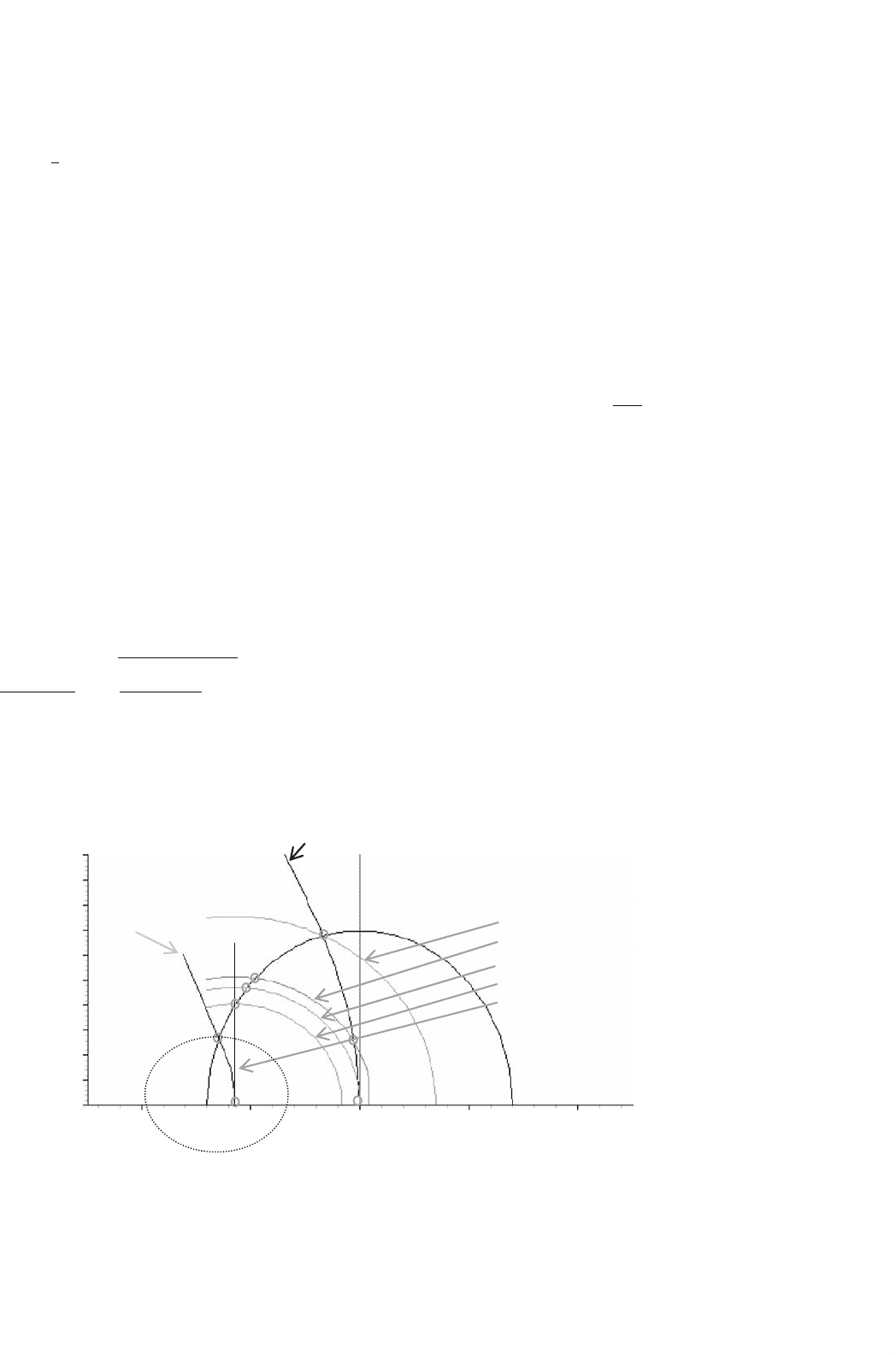
33.5.3.2.1 Operation with Maximum Torque per Ampere
(MTPA) Characteristic In this mode of control, the devel-
oped torque T per ampere of stator current is the highest for
a given rotor excitation. The combination of i
d
and i
q
that
develops the maximum torque per ampere of stator current
is indicated in Fig. 33.53. The reference signal for the inner
torque loop normally determines the i
q
reference; while the i
d
reference is given by
i
d
=
λ
f
2(L
q
−L
d
)
−
λ
2
f
4(L
q
−L
d
)
2
+i
2
q
(33.75)
It should be noted that with i
d
= 0, this mode of operation
is achieved for the surface-magnet motor.
i
d
, A
i
q
, A
Voltage limit
trajectory
Maximum torque per
ampere trajectory
Voltage limited
maximum output
trajectory
A
C
O
D
E
G
A
2
A
1
2
1.8
1.6
1.4
1.2
1
0.8
0.6
0.4
0.2
0
−2 −10 1 2
w = w
p
w = 1500 rpm = w
base
w = 2400 rpm = w
c
w = 2800 rpm = w
1
w > 2800 rpm
w = 2200 rpm
B
FIGURE 33.53 i
d
–i
q
Trajectories for the maximum torque per ampere characteristic and for maximum voltage and current limits of an interior
PM motor.
33.5.3.2.2 Operation with Voltage and Current Limits The
maximum current limit of the motor/inverter, I
smax
, is nor-
mally imposed by setting appropriate limits on i
d
and i
q
such
that
i
2
d
+i
2
q
I
2
s max
(33.76)
Equation (33.75) defines a circle around the origin of the
i
d
–i
q
plane.
The available dc-link voltage to the inverter places an upper
limit of the motor phase voltage, V
smax
, given by
V
2
= V
2
d
+V
2
q
≤ V
2
max
(33.77)
(L
q
i
q
)
2
+(L
d
i
d
+λ
f
)
2
≤
V
am
ω
2
(33.78)
where the stator voltages v
d
and v
q
are expressed in the rotor
reference frame, as in Eq. (33.68). Equation (33.78) is obtained
from the voltage equation of Eq. (33.68) when the phase
resistance R is neglected. Equation (33.78) defines elliptical tra-
jectories that contract as speed increases. All the three modes
of operation are included in Fig. 33.53.
33.5.3.2.3 Operation with Field Weakening This mode of
operation is normally required for operating the motor above
the base speed. A constant-power characteristic is normally
desired over the full field-weakening range. For a given rotor
excitation of λ
f
and developed power of P
0
, the developed
torque T and the net rotor flux linkage required for constant-
power operation can be determined. From this, the limiting
values for i
d
and i
q
, which further constrain the allowable i
d
–i
q
trajectory is also indicated in Fig. 33.53, can be determined.

33 Motor Drives 891
Trajectory
Generator
T
∗
i
∗
q
i
∗
d
FIGURE 33.54 i
d
and i
q
trajectory generation satisfying the desired
operating modes.
The operating modes described in the preceding section are
normally included in a trajectory controller that generates the
references for i
d
and i
q
continuously, as indicated in Fig. 33.54.
33.6 Permanent-magnet Brushless DC
Motor Drives
33.6.1 Machine Background
Anyone studying electric machines would be aware that the
classical synchronous machine offers the possibility of the very
highest efficiencies. These machines have the power-carrying
conductors in the stationary part, therefore there is no need to
transfer high power through a brush system. The field is pro-
vided on the rotating part either by an electromagnet, which
does require some very low-power brushes or at best, by a
permanent magnet with no power requirements at all.
This is clearly better than the traditional dc machine with
high-power brushes and rotating conductors, with those con-
ductors having a very poor path for heat to get away under
overload conditions. You might ask, “why did we use so many
of them?” It was of course because the dc machine offered the
ability to control the speed fully and easily, which the syn-
chronous machine, when running from the mains at a fixed
frequency, was definitely not capable of. Thus, for example, all
electric trains and trams built up to the 1980s, many of them
still in service, use brushed dc motors.
The induction machine, the work horse of industry is quite
efficient, but because of the need to carry magnetizing current
in the stator as well as load current, and the existence of slip, it
cannot be as good as the synchronous machine. It also innately
has a very limited speed range.
All this changed with the advent of inexpensive, reliable
power electronics. Quite suddenly power electronics engineers
had the ability to vary both the frequency and the amplitude
of an ac supply and thus to provide the holy grail of variable-
speed ac motors. This was first applied to induction machines,
with the simplest form of open-loop control. The complexity
of control for synchronous machines added substantially to the
cost and was not so appealing. Today the thought of putting a
digital signal processor (DSP) or a microcontroller in a small
motor controller is no longer as daunting as it was ten years
ago, so the distinction between the complexity of a controller
for induction machines and synchronous machines has almost
disappeared.
Whilst power electronics radically changed our attitudes to
electric machine design and operation, there was a second very
important development which arrived on the scene at almost
the same time; the appearance of very powerful rare earth
permanent-magnet materials.
The first rare earth magnet material was Samarium Cobalt,
used in very special applications such as space and defence,
but it was then, and still is, very expensive. Neodymium–Iron–
Boron (Nd–Fe–B) came next with even higher energy product.
Energy product is a measure used to quantify the effectiveness
of magnets. Nd–Fe–B began expensively, but has continued to
drop in price at a spectacular rate and recently became cheaper
than ferrites in term of dollars per unit of energy product.
Thus all the machines discussed here are permanent–magnet
(PM) machines, in general using Nd–Fe–B magnets.
33.6.1.1 Clarifying Torque Versus Speed Control
As is well understood, given a fixed magnetic flux level, the
magnitude of the current in a motor determines the magnitude
of the torque out of the machine. In a general application
if a torque is set, the speed is determined by the load. This
is what happens when driving an automobile. The throttle
or accelerator varies the torque. The speed can be very slow
or very high for the same foot position, depending on the
road conditions and vehicle motion history, even if the vehicle
is in the same gear. This principle of torque control rather
than speed control is fundamental to the operation of electric
machines. When speed control is required in PMBDCMs, it
is usual to implement torque control, with an extra outside
control loop, like a cruise control in an automobile, to use the
torque control to deliver speed control. So from here on the
discussion will describe torque control for the variable-speed
motor.
33.6.1.2 Permanent-magnet AC Machines
There are two quite different types of permanent-magnet
ac machines, actually looking very similar in their physi-
cal realization but dramatically different in their electrical
characteristics and in the way in which they are controlled.
33.6.1.2.1 Permanent-magnet Synchronous Machines
These are simple extensions of the classical synchronous
machine, where all of the voltages and currents are designed
to be sinusoidal functions of time, as they are in the syn-
chronous machine when used as a supply generator. These
machines are known as permanent-magnet synchronous
machines (PMSMs) or brushless ac machines and are discussed
elsewhere in this book. Whilst the application of sinusoidal
waveforms everywhere is comforting to many and does result
892 M. F. Rahman et al.
in less acoustic noise, less “stray losses” etc. there is in gen-
eral a requirement to know the exact rotor angular position
at every instant of time, with an accuracy in the order of one
degree. This knowledge is then used to shape the current wave-
forms to be sure that they are in phase with the back-emf of
the windings. Whilst much research is going on to run these
machines without position sensors, the reality in the workplace
today is that you need to include a relatively expensive shaft
position encoder with your PMSM, if you wish to control it
electronically.
33.6.1.2.2 Permanent-magnet Brushless DC Machines A
very much simpler possibility has emerged, which also gives
the benefits of smooth torque and rapid controllability. This
results in smaller minimum machine size, yielding maximum
machine power density.
For this variant, the current waveforms and the back-
emf waveforms are trapezoidal rather than sinusoidal. In this
case, the machine is known as a permanent-magnet brush-
less dc machine (PMBDCM), with waveforms as shown in
Fig. 33.55.
33.6.1.3 Brief Tutorial on Electric Machine Operation
The operation of electric machines can be explained in a variety
of ways. Two possible and different methods are by:
(1) Using an understanding of the interaction of magnetic
fields and the tendency of magnetic fields to align.
This tendency to align is what provides the force that
Ia
Ib
Ic
time
angleBr
360°180°
FIGURE 33.55 Phase currents as functions of time and the flux density
on the surface of the rotor as a function of angular position for a typical
PMBDCM.
makes a compass needle swing around, until it aligns
with the earth’s magnetic field.
(2) Using the physical principle that “a current carrying
conductor in a magnetic field has a force exerted on
it.” This force is commonly known as the Lorentz
force.
The difference between the two explanations is that the first
method gives better “physical pictures.” However when one
gets a little more serious, wanting to put in numbers, the force
equations, whilst not greatly more difficult, are a little more
challenging as they involve vector cross products.
With the second method, once the principle is accepted,
there is a particularly simple scalar version of the force equa-
tion that very rapidly and simply gives numeric answers.
The directions of the force, current, and motion are all
orthogonal, i.e. at right angles and a formal exposition would
again use a vector cross product. However, provided the rules
learned in high school science are applied, the scalar version,
F = BLI can be used, where F is the force in newtons, B is
the flux density in Tesla, L is the length of the conductor in
meters, and I is the current in amperes.
Let us try both the methods, on the simple machine of
Fig. 33.56.
The rotor is a magnet with a north and a south pole, and
there is a coil of wire in the slots in the stator. Current is
shown going into the conductor called a at the top of the sta-
tor and coming out of the conductor called a
at the bottom.
To simulate a real machine more closely, one should imagine
putting a one turn “coil” of wire into the slot, with a connec-
tion made at the back of the machine to connect the top wire
to the bottom, so that by applying a positive voltage to the top
wire and a negative voltage to the end of the coil (the bottom
wire), current will flow in at the top and out at the bottom as
discussed previously.
S
N
a
a'
FIGURE 33.56 A simple motor with a single coil in the stator and a
permanent-magnet rotor.
33 Motor Drives 893
Method 1 If the current is put into the top and comes out
of the bottom as marked, then according to the right-hand
rule (if you forget, then look at the Institution of Electrical
and Electronic Engineers (IEEE) logo), magnetic flux will be
forced to go through the center of the coil from right to the
left, creating a north pole on the left. The flux will then double
back through the iron frame of the motor to arrive back at the
South pole on the right.
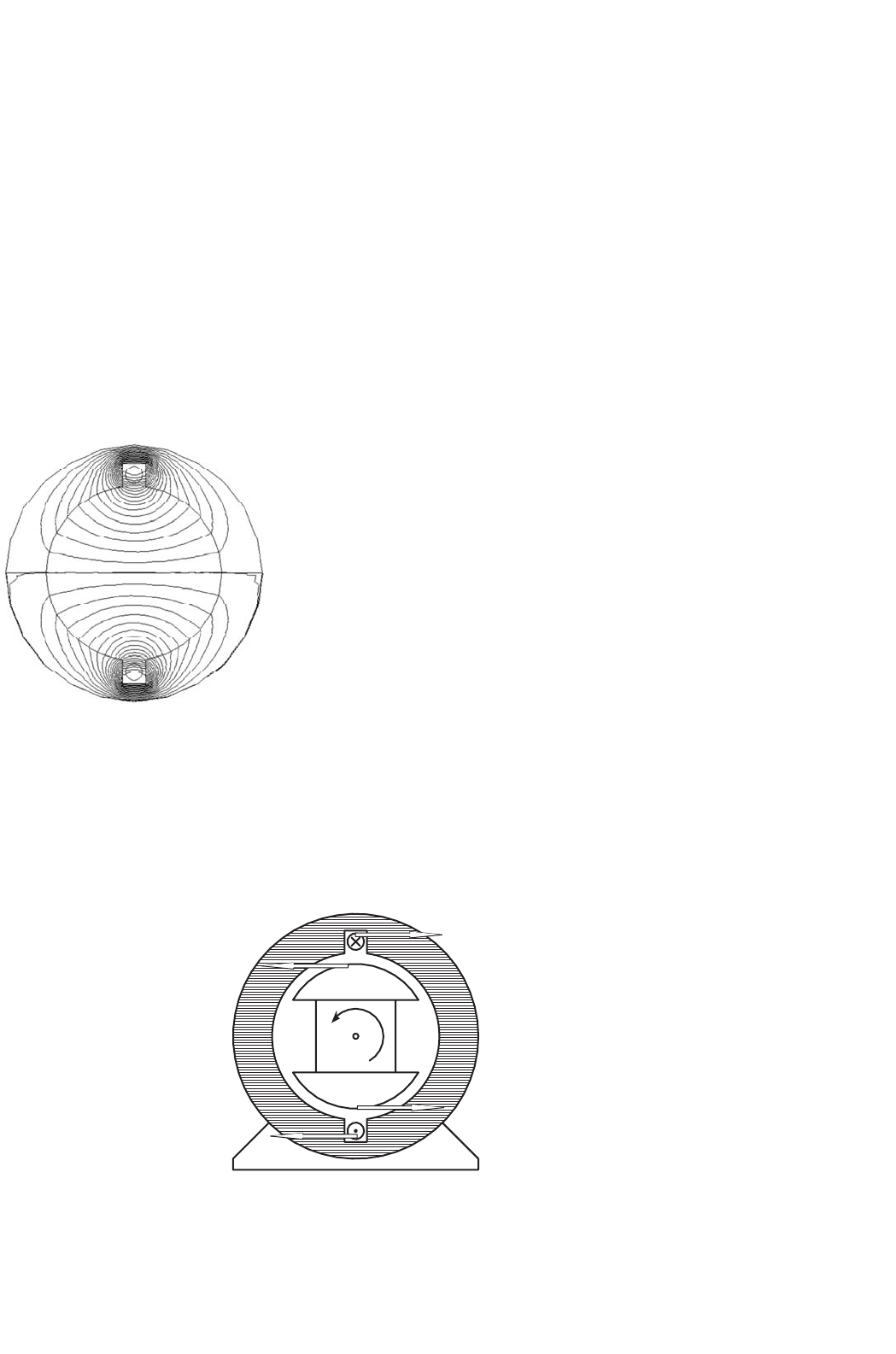
Figure 33.57 shows a computer generated magnetic field
plot. This was produced using finite element analysis and mod-
eling the stator as electrical steel, the volume in the center as
air and injecting current into the coil.
If the permanent-magnet rotor is then put inside the
stator of Fig. 33.57, the rotor will align by rotating 90
◦
counterclockwise.
FIGURE 33.57 A computer generated magnetic field for current in the
windings and a stator made of electrical steel.
Method 2 In this case, looking at Fig. 33.58, the conductor
a will be immersed in a quite dense field produced by the
magnets, with the flux lines going up the page in the rotor,
S
N
a
a'
Force on conductor a
Reaction force on magnet N
Force on conductor a′
Reaction force on magnet S
FIGURE 33.58 Lorentz forces on conductor and rotor of a simple machine.
across the airgap into the steel of the stator, heading down the
stator to jump back across the lower airgap to return to the
south pole. If a current is directed into the upper conductor
and out of the bottom as before, it will produce force. Applying
the direction rules associated with the Lorentz force, the force
on the conductor will be to the right at the top and to the left
at the bottom. Invoking Newton’s third law, that action and
reaction are equal and opposite, it is clear that if the wire is
fixed, as it is, then there will be a force on the rotor to the left
at the top and to the right at the bottom, thus the rotor will
move counterclockwise as before.
33.6.2 Electronic Commutation
If the rotor of Fig. 33.58 moves, then to keep it rotating in the
same direction, sooner or later the current in the conductors
must be reversed. The time at which that needs to be done is
when the rotor has moved to an almost aligned position, so it is
not really a matter of time, but a matter of rotor position. Since
the rotor is a permanent magnet, it is a very simple matter
to determine at least where the physical pole edges are, using
simple, reliable and inexpensive Hall effect (HE) sensors. These
are small semiconductor devices which respond to magnetic
flux density. (There are many ways to sense the position of the
rotor; however the remainder of this exposition will stay with
the HE sensor for simplicity.)
A very simple motor, relying on the inertia of the rotor for
continuous rotation, could have a control circuit which sensed
when the rotor magnet was horizontal and then reversed the
current in aa
of Fig. 33.58.
The traditional “H” bridge switching circuit shown in
Fig. 33.59 does that very effectively. Switch drive logic must
ensure that either S1 and S4 are on, or S2 and S3 are on and
never S1 and S2 simultaneously, or S3 and S4 simultaneously.
This simultaneous operation would provide a short circuit.
When this happens due to errors in the switch drive signal it
is called “shoot through.” There are generally important parts

894 M. F. Rahman et al.
+
a
a′
S1
S2
S3
S4
−
V
in
FIGURE 33.59 An “H” bridge circuit that can reverse the current
through aa
, as drawn with mechanical switches.
of the switch drive signal logic, discussed later, which try to
make this impossible in normal operation.
In real motors, the permanent-magnet rotor field does
not change instantaneously from north to south as the rotor
rotates, so there would be reasonably large angles over which
the torque could not be effectively produced. Also more coils
are put in so that the space of the machine frame is used more
efficiently.
The use of three “phases,” as in Fig. 33.60, is very common.
There are many things which balance naturally in a three-phase
system and it is the simplest system with which it is possible
to develop constant and unidirectional torque at all times and
positions.
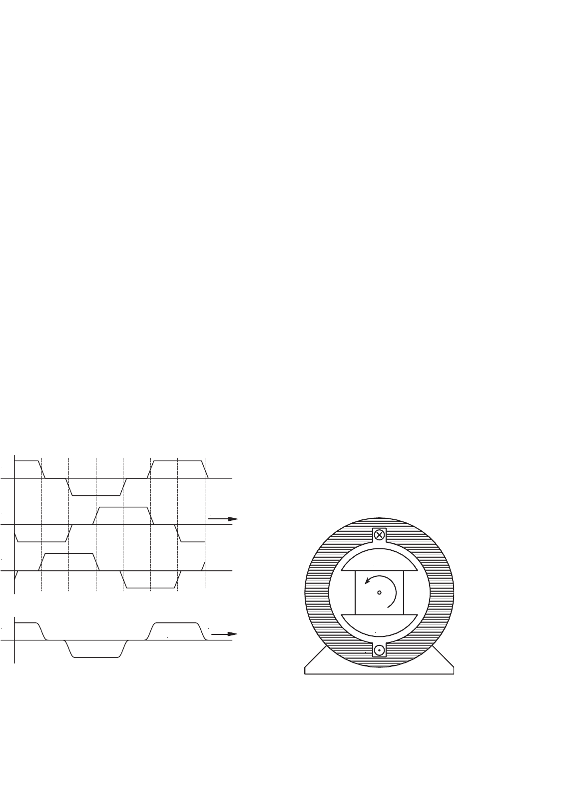
A very common method has developed, known as “six step
switching.” In this system, three phases are used. They are
connected in star and there is a space between each of the
N
S
a
a′
b
b′
c
c′
FIGURE 33.60 The physical layout of a three-phase PMBDCM.
magnet poles on the rotor and the two phases are activated
at any one time, the third “resting” as the space between the
magnet poles passes over it.
While the motor in Fig. 33.60 looks just like a three-phase
synchronous machine, its operation is rather different.
As stated above, the windings are invariably star connected,
as shown in Fig. 33.61.
a
c
b′
b
a′
c′
FIGURE 33.61 The schematic connection of the windings shown in
Fig. 33.60.
Six Step Switching Explained
Consider the coil aa
, as shown in Fig. 33.60 and also diagram-
matically in Fig. 33.61. Current driven into the a terminal,
coming out of the a
terminal, will produce, as discussed
before, flux from left to right, as shown here.
Obviously if the current direction in aa
is reversed, the flux
will be
Similarly if current is driven into b and out of b
flux will result
And if it is reversed,
33 Motor Drives 895
Finally, if current is driven into c and out of c
, flux will result
And if it is reversed,
The permanent-magnet rotor would tend to align with the
flux arrow shown in each of the states above, as discussed
under machine operation, Method 1.
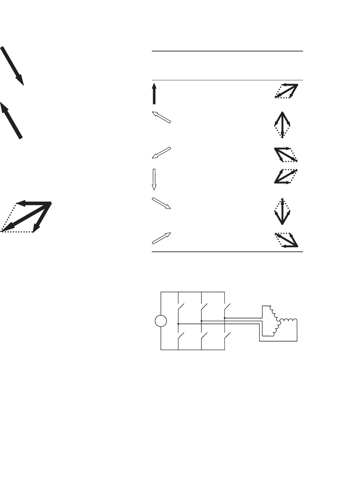
Now if the motor is wired in star as shown in Fig. 33.61,
and a steady current is driven into a and out of b, the first and
the fourth cases above occur at the same time. They add to
produce a resultant,
and the rotor will tend to align with this resultant.
The Hall effect sensors are positioned so that just as the rotor
gets to within 60
◦
of being aligned, another arrangement of the
windings is energized, and the field jumps forward another
60
◦
, so the rotor is 120
◦
away from being aligned. The rotor is
always an average of 90
◦
away from its desired position!
If a controller has input power from positive and negative of
a dc supply and outputs to the terminals a, b, and c only, then
the sequence of connections shown in Table 33.2 will produce
the resultant flux directions as shown, providing continuous
rotation.
The switching of Table 33.2 is simply achieved by a vari-
ant of the “H” bridge, as shown in Fig. 33.62. This process of
switching current into different windings is called commuta-
tion and is the equivalent of the sliding brush contacts in a
traditional brushed dc machine.
33.6.3 Current/Torque Control
You may have noted that the discussion has been about current
in the windings rather than the voltage across them. In very
simple small brushless DC machines, like the one in the muffin
fan in your computer power supply, voltages are connected
directly to the windings. For these small motors, the resistance
of the windings is relatively high and this helps limit the actual
current that flows and swamps inductive effects.
TABLE 33.2 The sequence of connections which results in counterclock-
wise continuous rotation of the rotor of the PMBDCM of Fig. 33.60
When rotor gets
to this position,
connections are
made as at right
Terminal a Terminal b Terminal c Flux directions
Current in Current out Zero
Zero Current out Current in
Current out Zero Current in
Current out Current in Zero
Zero Current in Current out
Current in Zero Current out
+
a
a′
S1
S2
S3
S4
−
S5
S6
b
b′
c
c′
FIGURE 33.62 The switching circuit used for commutation of a
PMBDCM.
There is an extra difficulty that must be addressed with high-
performance, high-efficiency, well-made machines, and it adds
another layer to the control of the motor. Such machines can
easily be designed with very low resistance windings. It is not
uncommon to have windings for a 200 V machine at the 20 kw
level with the winding resistances less than 0.1 .