Power electronic handbook
Подождите немного. Документ загружается.

774 V. K. Sood
Examples of this type of application abound from the earlier
Pacific Intertie to the recent links in China and India.
The breakeven distance is being effectively decreased with
the reduced costs of new compact converter stations possible
due to the recent advances in power electronics (discussed in
a later section).
Asynchronous interconnection of ac systems
In terms of an asynchronous interconnection between two
ac systems, the dc option reigns supreme. There are many
instances of BB connections where two ac networks have been
tied together for the overall advantage to both ac systems. With
recent advances in control techniques, these interconnections
are being increasingly made at weak ac systems. The growth
of BB interconnections is best illustrated with the example
of North America where the four main independent power
systems are interconnected with 12 BB links.
In the future, it is anticipated that these BB connection will
also be made with VSCs offering the possibility of full four-
quadrant operation and the total control of active/reactive
power coupled with the minimal generation of harmonics.
Stabilization of power flows in integrated power system
In large interconnected systems, power flow in ac ties (partic-
ularly under disturbance conditions) can be uncontrolled and
lead to overloading and stability problems, thus endangering
system security. Strategically placed dc lines can overcome this
problem due to the fast controllability of dc power and pro-
vide much needed damping and timely overload capability.
The planning of dc transmission in such applications requires
detailed study to evaluate the benefits. Examples are the IPP
link in the USA and the Chandrapur–Padghe link in India.
Presently the number of dc lines in a power grid is very
small compared to the number of ac lines. This indicates
that dc transmission is justified only for specific applications.
Although advances in technology and introduction of mul-
titerminal dc (MTDC) systems are expected to increase the
scope of application of dc transmission, it is unlikely that the
ac grid will be replaced by a dc power grid in the future. There
are two major reasons for this. First, the control and protection
of MTDC systems is complex and the inability of voltage trans-
formation in dc networks imposes economic penalties. Second,
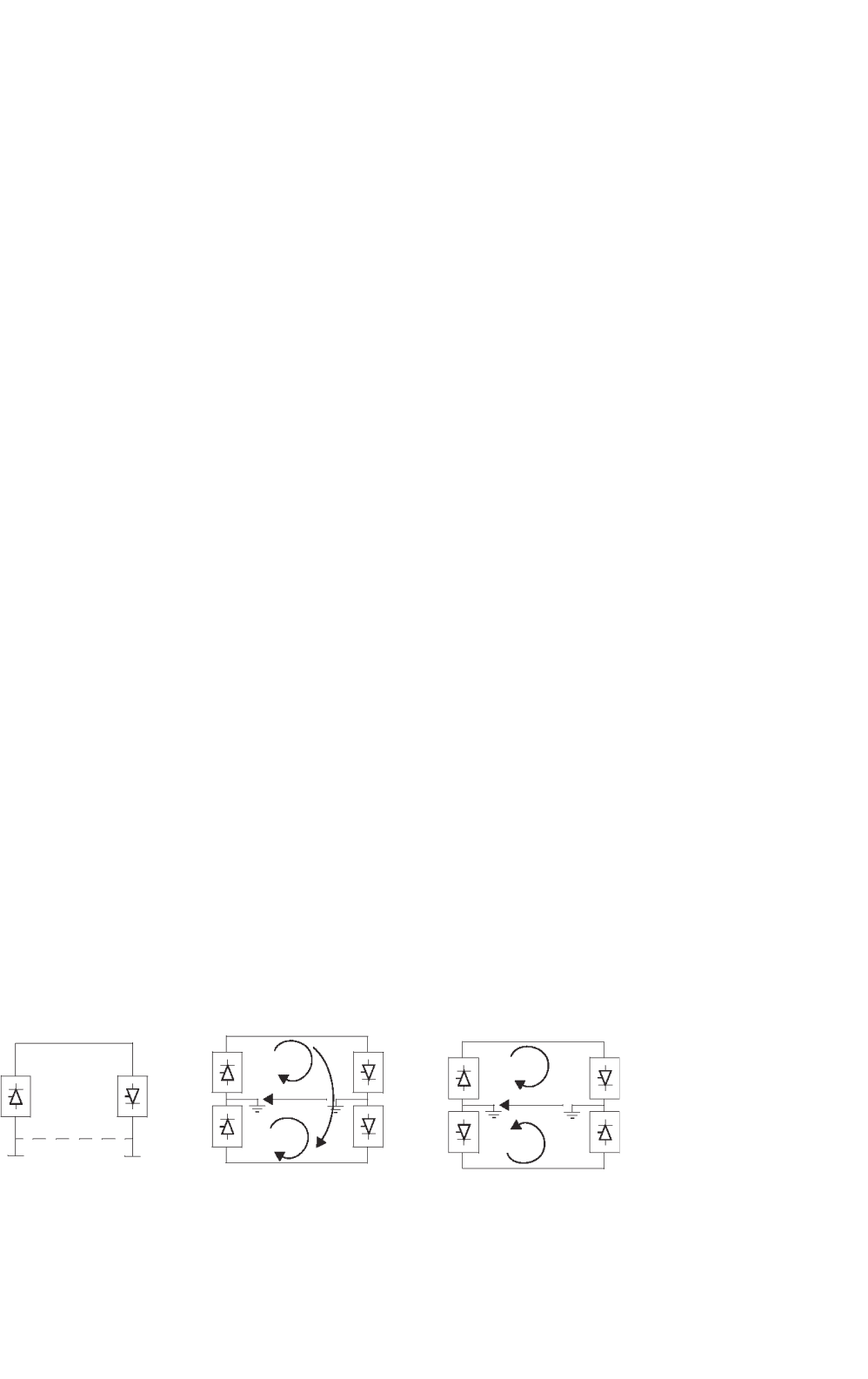
(a) (b)
no current
2I
d
(c)
FIGURE 30.3 Types of HVDC links: (a) monopolar link; (b) bipolar link; and (c) homopolar link.
the advances in power electronics technology have resulted in
the improvement of the performance of ac transmissions using
FACTS devices, for instance through introduction of static var
systems, static phase shifters, etc.
30.1.4 Types of HVDC Systems
Three types of dc links are considered.
30.1.4.1 Monopolar Link
A monopolar link (Fig. 30.3a) has one conductor and uses
either ground- and/or sea-return. A metallic return can also
be used where concerns for harmonic interference and/or cor-
rosion exist. In applications with dc cables (i.e. HVDC light),
a cable return is used. Since the corona effects in a dc line
are substantially less with negative polarity of the conduc-
tor as compared to the positive polarity, a monopolar link
is normally operated with negative polarity.
30.1.4.2 Bipolar Link
A bipolar link (Fig. 30.3b) has two conductors, one with posi-
tive and the other with negative polarity. Each terminal has two
sets of converters of equal rating, in series on the dc side. The
junction between the two sets of converters is grounded at one
or both ends by the use of a short electrode line. Since both
poles operate with equal currents under normal operation,
there is zero ground current flowing under these conditions.
Monopolar operation can also be used in the early stages of
the development of a bipolar link. Alternatively, under faulty
converter conditions, one dc line may be temporarily used as
a metallic return with the use of suitable switching.
30.1.4.3 Homopolar Link
In this type of link (Fig. 30.3c), two conductors having the
same polarity (usually negative) can be operated with ground
or metallic return.
Due to the undesirability of operating a dc link with ground
return, bipolar links are mostly used. A homopolar link has the
advantage of reduced insulation costs, but the disadvantages
of earth return outweigh the advantages.
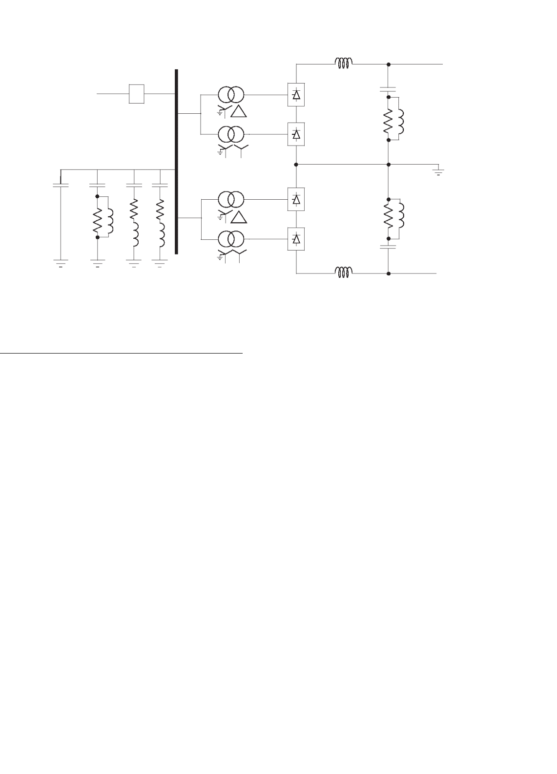
30 HVDC Transmission 775
AC Breaker
AC filters
Converter
transformers
DC filters
Smoothing reactor
Electrode line
FIGURE 30.4 Typical HVDC converter station equipment.
30.2 Main Components of HVDC
Converter Station
The major components of a HVDC transmission system are
the converter stations at the ends of the transmission sys-
tem. In a typical two-terminal transmission system, both a
rectifier and an inverter are required. The role of the two sta-
tions can be reversed, as controls are usually available for both
functions at the terminals. The major components of a typ-
ical 12-pulse bipolar HVDC converter station (Fig. 30.4) are
discussed below.
30.2.1 Converter Unit
This usually consists of two three-phase converter bridges con-
nected in series to form a 12-pulse converter unit. The design
of valves is based on a modular concept where each mod-
ule contains a limited number of series-connected thyristor
levels. The valves can be packaged either as a single-valve,
double-valve, or quadruple-valve arrangement. The converter
is fed by two converter transformers, connected in star/star
and star/delta arrangement, to form a 12-pulse pair. The valves
may be cooled by air, oil, water, or freon. However, the cooling
using deionized water is more modern and considered efficient
and reliable. The ratings of a valve group are limited more by
the permissible short-circuit currents than by the steady-state
load requirements.
Valve firing signals are generated in the converter control at
ground potential and are transmitted to each thyristor in the
valve through a fiber-optic light guide system. The light signal
received at the thyristor level is converted to an electrical signal
using gate drive amplifiers with pulse transformers. Recent
trends in the industry indicate that direct optical firing of the
valves with light triggered thyristors (LTTs) is also feasible.
The valves are protected using snubber circuits, protective
firing, and gapless surge arresters.
30.2.1.1 Thyristor Valves
Many individual thyristors are connected in series to build
up an HVDC valve. To distribute the off-state valve voltage
uniformly across each thyristor level and protect the valve from
di/dt and dv/dt stresses, special snubber circuits are used across
each thyristor level (Fig. 30.5).
The snubber circuit is composed of the following compo-
nents:
• A saturating reactor is used to protect the valve from di/dt
stresses during turn-on. The saturating reactor offers a
high inductance at low current and a low inductance at
high current.
• A dc grading resistor, RG distributes the direct voltage
across the different thyristor levels. It is also used as a
voltage divider to measure the thyristor level voltage.
• The RC snubber circuits are used to damp out voltage
oscillations from power frequency to a few kilohertz.
• A capacitive grading circuit, CFG is used to protect the
thyristor level from voltage oscillations at a much higher
frequency.
A thyristor is triggered ON by a firing pulse sent via a
fiber-optic cable from the valve base electronics (VBE) unit
at earth potential. The fiber-optic signal is amplified by a gate
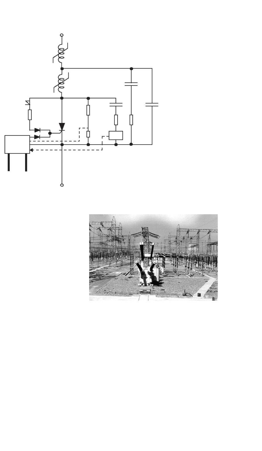
776 V. K. Sood
FIRING DATABACK
Optical fibers
Gate
Electronics
Breakover
diode
Saturating
reactor
R
G
C
D1
R
D1
R
D2
PSU
C
FG
C
D2
FIGURE 30.5 Electrical circuit of the thyristor level [2].
electronic unit (GEU), which receives its power from the RC
snubber circuit during the valve’s OFF period. The GEU can
also affect the protective firing of the thyristor independent of
the central control unit. This is achieved by a breakover diode
(BOD) via a current limiting resistor that triggers the thyristor
when the forward voltage threatens to exceed the rated voltage
for the thyristor. This may arise in a case when some thyristors
may block forward voltage while others may not.
It is normal to include some extra redundant thyristor levels
to allow the valve to remain in service after the failure of some
thyristors. A metal oxide surge arrestor is also used across each
valve for overvoltage protection.
The thyristors produce considerable heat loss, typically
24–40 W/cm
2
(or over 1 MW for a typical quadruple valve),
and so an efficient cooling system is essential.
30.2.2 Converter Transformer
The converter transformer (Fig. 30.6) can have different con-
figurations: (a) three phase, two-winding, (b) single-phase,
three-winding, and (c) single-phase, two-winding. The valve-
side windings are connected in star and delta with neutral
point ungrounded. On the ac side, the transformers are con-
nected in parallel with the neutral grounded. The leakage
impedance of the transformer (typical value between 15 and
18%) is chosen to limit the short-circuit currents through any
valve.
FIGURE 30.6 Spare converter transformer in the switchyard of an
HVDC station.
The converter transformers are designed to withstand dc
voltage stresses and increased eddy current losses due to har-
monic currents. One problem that can arise is due to the
dc magnetization of the core due to unsymmetrical firing of
valves.
30.2.3 Filters
Due to the generation of characteristic and non-characteristic
harmonics by the converter, it is necessary to provide suitable
30 HVDC Transmission 777
filters on the ac–dc sides of the converter to improve the
power quality and meet telephonic and other requirements.
Generally, three types of filters are used for this purpose.
30.2.3.1 AC Filters
AC Filters (Fig. 30.7) are passive circuits used to provide low
impedance, shunt paths for ac harmonic currents. Both tuned
and damped filter arrangements are used. In a typical 12-pulse
station, filters at 11th, 13th harmonics are required as tuned
filters. Damped filters (normally tuned to the 23rd harmonic)
are required for the higher harmonics. In recent years, C-type
filters have also been used since they provide more economic
designs. Double- or even triple-tuned filters exist to reduce the
cost of the filter (see Fig. 30.23).
The availability of cost-effective active ac filters will change
the scenario in the future.
30.2.3.2 DC Filters
These are similar to ac filters and are used for the filtering of
dc harmonics. Usually a damped filter at the 24th harmonic
is utilized. Modern practice is to use active dc filters (see also
the application example system presented later). Active dc fil-
ters are increasingly being used for efficiency and space saving
purposes.
30.2.3.3 High Frequency (RF/PLC) Filters
These are connected between the converter transformer and
the station ac bus to suppress any high-frequency currents.
Sometimes such filters are provided on the high-voltage dc
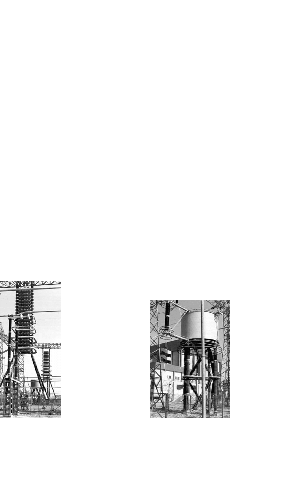
FIGURE 30.7 Installation of an ac filter in the switchyard.
bus connected between the dc filter and dc line and also on
the neutral side.
30.2.4 Reactive Power Source
Converter stations consume reactive power that is dependent
on the active power loading (typically about 50–60% of the
active power). The ac filters provide a part of this reactive
power requirement. In addition, shunt (switched) capacitors
and static var systems are also used.
30.2.5 DC Smoothing Reactor
A sufficiently large series reactor is used on the dc side of
the converter to smooth the dc current and for the converter
protection from line surges. The reactor (Fig. 30.8) is usually
designed as a linear reactor and may be connected on the line
side, neutral side, or at an intermediate location. Typical values
of the smoothing reactor are in the range 240–600 mH for long
distance transmission and about 24 mH for a BB connection.
30.2.6 DC Switchgear
This is usually a modified ac equipment and used to inter-
rupt only small dc currents (i.e. employed as disconnecting
switches). DC breakers or metallic return transfer breakers
(MRTB) are used, if required, for the interruption of rated
load currents.
In addition to the equipment described above, ac switchgear
and associated equipment for protection and measurement are
also part of the converter station.
FIGURE 30.8 Installation of an air-cooled smoothing reactor.
778 V. K. Sood
30.2.7 DC Cables
Contrary to the use of ac cables for transmission, dc cables
do not have a requirement for continuous charging current.
Hence the length limit of about 50 km does not apply. More-
over, dc voltage gives less aging and hence a longer lifetime
for the cable. The new design of HVDC light cables from ABB
are based on extruded polymeric insulating material instead
of classic paper-oil insulation that has a tendency to leak. Due
to their rugged mechanical design, flexibility, and low weight,
polymer cables can be installed in underground cheaply with a
plowing technique, or in submarine applications, it can be laid
in very deep waters and on rough sea-bottoms. Since dc cables
are operated in bipolar mode, one cable with positive polarity
and one cable with negative polarity, very limited magnetic
fields result from the transmission. HVDC light cables have
successfully achieved operation at a stress of 20 kV/mm.
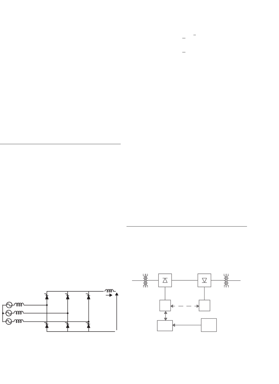
30.3 Analysis of Converter Bridge
To consider the theoretical analysis of a conventional 6-pulse
bridge (Fig. 30.9), the following assumptions are made:
• DC current I
d
is considered constant.
•
Valves are ideal switches.
•
AC system is strong (infinite).
Due to the leakage impedance of the converter transformer,
commutation from one valve to the next is not instantaneous.
An overlap period is necessary and, depending on the leakage,
either two, three, or four valves may conduct at any time. In
the general case, with a typical value of converter transformer
leakage impedance of about 13–18%, either two or three valves
conduct at any one time.
The analysis of the bridge gives the following dc output
voltages:
For a rectifier:
V
dr
= V
dor
·cos α −R
cr
·I
d
(30.1)
T4
T6 T2
Vd
T5
Id
T3
T1
Ld
Lc
e
a
e
b
e
c
FIGURE 30.9 Six-pulse bridge circuit.
where
V
dor
=
3
π
·
√
2 ·V
LL
R
cr
=
3
π
·ωL
cr
where
ω = 2 ·π ·f
where “f ” is the power frequency.
For an inverter:
There are two options possible depending on choice of the
delay angle or extinction angle as the control variable
−V
di
= V
doi
·cos β − R
ci
·I
d
(30.2)
−V
di
= V
doi
·cos γ −R
ci
·I
d
(30.3)
where
V
dr
and V
di
– dc voltage at the rectifier and inverter
respectively.
V
dor
and V
doi
– open circuit dc voltage at the rectifier and
inverter respectively.
R
cr
and R
ci
– equivalent commutation resistance at the
rectifier and inverter respectively.
L
cr
and L
ci
– leakage inductance of converter transformer at
rectifier and inverter respectively.
I
d
– dc current.
α – delay angle.
β – advance angle at the inverter, (β = π −α).
γ – extinction angle at the inverter, γ = π − α − µ.
30.4 Controls and Protection
In a typical two-terminal dc link connecting two ac systems
(Fig. 30.10), the primary functions of the dc controls are to:
• Control the power flow between the terminals.
• Protect the equipment against the current/voltage stresses
caused by faults.
Master Controls
Local Controls
AC system 1
DC System
Telecoms
AC System 2
Dispatch center
FIGURE 30.10 Typical HVDC system linking two ac systems.

30 HVDC Transmission 779
• Stabilize the attached ac systems against any operational
mode of the dc link.
The dc terminals each have their own local controllers.
A centralized dispatch center will communicate a power order
to one of the terminals that will act as a master controller and
has the responsibility to coordinate the control functions of
the dc link. Besides the primary functions, it is desirable that
the dc controls have the following features:
• Limit the maximum dc current: Due to a limited thermal
inertia of the thyristor valves to sustain overcurrents, the
maximum dc current is usually limited to less than 1.2 pu
for a limited period of time.
• Maintain a maximum dc voltage for transmission: This
reduces the transmission losses, and permits optimization
of the valve rating and insulation.
• Minimize reactive power consumption: This implies that
the converters must operate at a low firing angle. A typ-
ical converter will consume reactive power between 50
and 60% of its MW rating. This amount of reactive
power supply can cost about 15% of the station cost,
and comprise about 10% of the power loss.
The desired features of the dc controls are indicated below:
1. Limit maximum dc current: Since the thermal inertia
of the converter valves is quite low, it is desirable to
limit the dc current to prevent failure in the valves.
2. Maintain maximum dc voltage for transmission pur-
poses to minimize losses in the dc line and converter
valves.
3. Keep the ac reactive power demand low at either con-
verter terminal: This implies that the operating angles
at the converters must be kept low. Additional benefits
of doing this are to reduce the snubber losses in the
valves and reduce the generation of harmonics.
4. Prevent commutation failures at the inverter station
and hence improve the stability of power transmission.
5. Other features, i.e. the control of frequency in an
isolated ac system or to enhance power system stability.
In addition to the above desired features, the dc controls will
have to cope with the steady-state and dynamic requirements
of the dc link, as shown in Table 30.2.
TABLE 30.3 Choice of control strategy for two-terminal dc link
Condition no. Desirable features Reason Control implementation
1 Limit the maximum dc current, I
d
For the protection of valves Use constant current control at the rectifier
2 Employ the maximum dc voltage, V
d
For reducing power transmission losses Use constant voltage control at the inverter
3 Reduce the incidence of commutation failures For stability purposes Use minimum extinction angle control at inverter
4 Reduce reactive power consumption at the
converters
For voltage regulation and economic
reasons
Use minimum firing angles
TABLE 30.2 Requirements of the dc link
Steady-state requirements Dynamic requirements
Limit the generation of
non-characteristic harmonics
Step changes in dc current or
power flow
Maintain the accuracy of the
controlled variable, i.e. dc current
and/or constant extinction angle
Start-up and fault induced
transients
Cope with the normal variations in
the ac system impedances due to
topology changes
Reversal of power flow
Variation in frequency of
attached ac system
30.4.1 Basics of Control for a Two-terminal
DC Link
From converter theory, the relationship between the dc voltage
V
d
and dc current I
d
is given by Eqs. (30.1)–(30.3). These three
characteristics represent straight lines on the V
d
–I
d
plane.
Notice that Eq. (30.2), i.e. beta characteristic, has a positive
slope while the Eq. (30.3), i.e. gamma characteristic, has a
negative slope. The choice of the control strategy for a typical
two-terminal dc link is made according to the conditions in
the Table 30.3.
Condition 1 implies the use of the rectifier in constant
current control mode and condition 3 implies the use of
the inverter in constant extinction angle (CEA) control
mode. Other control modes may be used to enhance the
power transmission during contingency conditions depend-
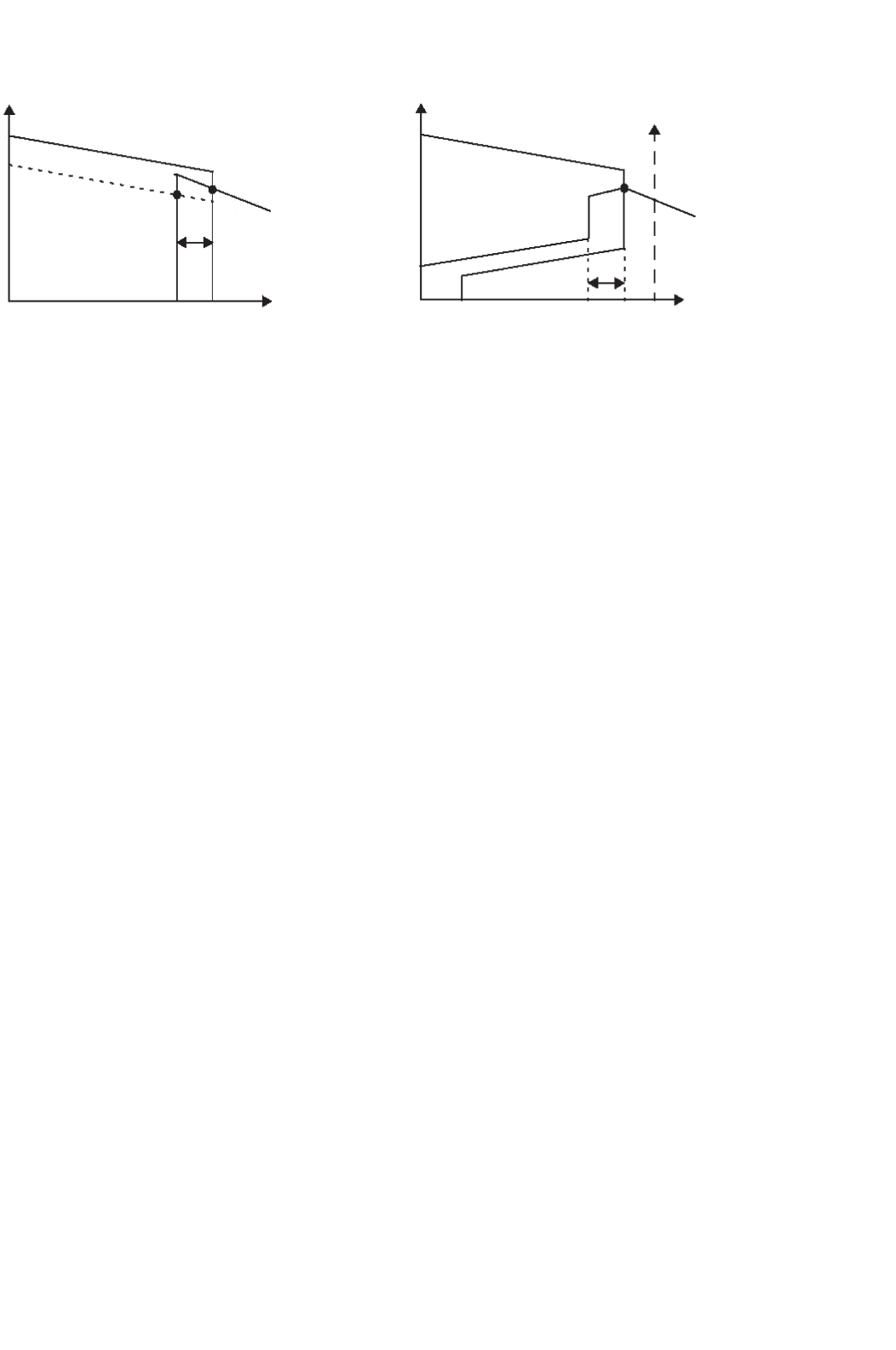
ing upon applications. This control strategy is illustrated in
Fig. 30.11.
The rectifier characteristic is composed of two control
modes: alpha-min (line AB) and constant current (line BC).
The alpha-min mode of control at the rectifier is imposed by
the natural characteristics of the rectifier ac system, and the
ability of the valves to operate when alpha is equal to zero,
i.e. in the limit the rectifier acts a diode rectifier. However,
since a minimum positive voltage is desired before firing of
the valves to ensure conduction, an alpha-min limit of about
2–5
◦
is typically imposed.
780 V. K. Sood
(a)
V
d
V
d
I
d
I
d
I
di
I
max
limit = 1.2 pu
I
dr
I
min
=0.2 pu
VDCL
CEA
α-min-limit-in-inverter
α-min-limit-in-rectifier
A
Q
B
Y
X
P
R
C
(b)
∆I
∆I
FIGURE 30.11 Static V
d
–I
d
characteristic for a two-terminal link: (a) unmodified and (b) modified.
The inverter characteristic is composed of two modes:
gamma-min (line PQ) and constant current (line QR). The
crossover point X of the two characteristics defines the oper-
ating point for the dc link. In addition, a constant current
characteristic is also used at the inverter. However, the cur-
rent demanded by the inverter I
di
is usually less than the
current demanded by the rectifier I
dr
by the current margin
I which is typically about 0.1 pu; its magnitude is selected
to be large enough so that the rectifier and inverter constant
current modes do not interact due to any current harmonics
which may be superimposed on the dc current. This control
strategy is termed as the current margin method.
The advantage of this control strategy becomes evident if
there is a voltage decrease at the rectifier ac bus. The operating
point then moves to point Y. In this way, the current transmit-
ted will be reduced to 0.9 pu of its previous value and voltage
control will shift to the rectifier. However, the power trans-
mission will be largely maintained near to 90% of its original
value.
The control strategy usually employs the following other
modifications to improve the behavior during system distur-
bances:
At the rectifier:
1. Voltage dependent current limit, VDCL
This modification is made to limit the dc current as
a function of either the dc voltage or, in some cases,
the ac voltage. This modification assists the dc link to
recover from faults. Variants of this type of VDCL do
exist. In one variant, the modification is a simple fixed
value instead of a sloped line.
2. I
d
-min limit
This limitation (typically 0.2–0.3 pu) is to ensure a
minimum dc current to avoid the possibility of dc
current extinction caused by the valve current drop-
ping below the hold-on current of the thyristors; an
eventuality that could arise transiently due to harmon-
ics superimposed on the low value of the dc current.
The resultant current chopping would cause high over-
voltages to appear on the valves. The magnitude of
I
d
-min is affected by the size of the smoothing reactor
employed.
At the inverter:
1. Alpha-min limit at inverter
The inverter is usually not permitted to operate inad-
vertently in the rectifier region, i.e. a power reversal
occurring due to an inadvertent current margin sign
change. To ensure this, an alpha-min-limit in inverter
mode of about 100–110
◦
is imposed.
2. Current error region
When the inverter operates into a weak ac system, the
slope of the CEA control mode characteristic is quite
steep and may cause multiple crossover points with
the rectifier characteristic. To avoid this possibility,
the inverter CEA characteristic is usually modified into
either a constant beta characteristic or constant voltage
characteristic within the current error region.
30.4.2 Control Implementation
30.4.2.1 Historical Background
The equidistant pulse firing control systems used in mod-
ern HVDC control systems were developed in the mid-
1960s [5, 6]; although improvements have occurred in their
implementation since then, such as the use of microproces-
sor based equipment, their fundamental philosophy has not
changed much. The control techniques described in [5, 6]
are of the pulse frequency control (PFC) type as opposed
to the now-out-of-favor pulse phase control (PPC) type. All
these controls use an independent voltage controlled oscilla-
tor (VCO) to decouple the direct coupling between the firing
pulses and the commutation voltage, V
com
. This decoupling
was necessary to eliminate the possibility of harmonic insta-
bility detected in the converter operation when the ac system
capacity became nearer to the power transmission capacity
30 HVDC Transmission 781
of the HVDC link, i.e. with the use of weak ac systems.
Another advantage of the equidistant firing pulse control was
the elimination of non-characteristic harmonics during steady-
state operation. This was a prevalent feature during the use
of the earlier individual phase control (IPC) system where
the firing pulses were directly coupled to the commutation
voltage, V
com
.
30.4.2.2 Firing Angle Control
To control the firing angle of a converter, it is necessary to
synchronize the firing pulses emanating from the ring counter
to the ac commutation voltage that has a frequency of 60 Hz
in steady state. However, it was noted quite early on (early
1960s), that the commutation voltage (system) frequency is
not a constant, neither in frequency nor in amplitude, during a
perturbed state. However, it is the frequency that is of primary
concern for the synchronization of firing pulses. For strong
ac systems, the frequency is relatively constant and distortion
free to be acceptable for most converter type applications. But,
as converter connections to weak ac systems became required
more often than not, it was necessary to devise a scheme for
synchronization purposes which would be decoupled from the
commutation voltage frequency for durations when there were
perturbations occurring on the ac system. The most obvious
method is to utilize an independent oscillator at 60 Hz that
can be synchronously locked to the ac commutation voltage
frequency. This oscillator would then provide the (phase) ref-
erence for the generation of firing pulses to the ring counter
during the perturbation periods, and would use the steady-
state periods for locking in step with the system frequency.
The advantage of this independent oscillator would be to
provide an ideal (immunized and clean) sinusoid for synchro-
nizing and timing purposes. There are two possibilities for this
independent oscillator:
•
Fixed frequency operation.
• Variable frequency operation.
Use of a fixed frequency oscillator (although feasible, and
called the PPC oscillator) is not recommended, since it is
known that the system frequency does drift, between 55 and
I
or
I
d
K/(1 + sT) VCO
Ring
Counter
DCCT
I
e
I
d
α
o
+
–
FIGURE 30.12 Control loop for the rectifier.
65 Hz, due to the rotating machines used to generate elec-
tricity. Therefore, it is preferable to use a variable frequency
oscillator (called the PFC oscillator) with a locking range of
between 50 and 70 Hz and the center frequency of 60 Hz. This
oscillator would then need to track the variations in the system
frequency and a control loop of some sort would be used for
this tracking feature; this control loop would have its own gain
and time parameters for steady-state accuracy and dynamic
performance requirements.
The control loop for frequency tracking purposes would also
need to consider the mode of operation for the dc link. The
method widely adopted for dc link operation is the so-called
current margin method.
30.4.3 Control Loops
Control loops are required to track the following variables:
•
Ordered current I
or
at the rectifier and the inverter.
• Ordered extinction angle (γ
o
) at the inverter.
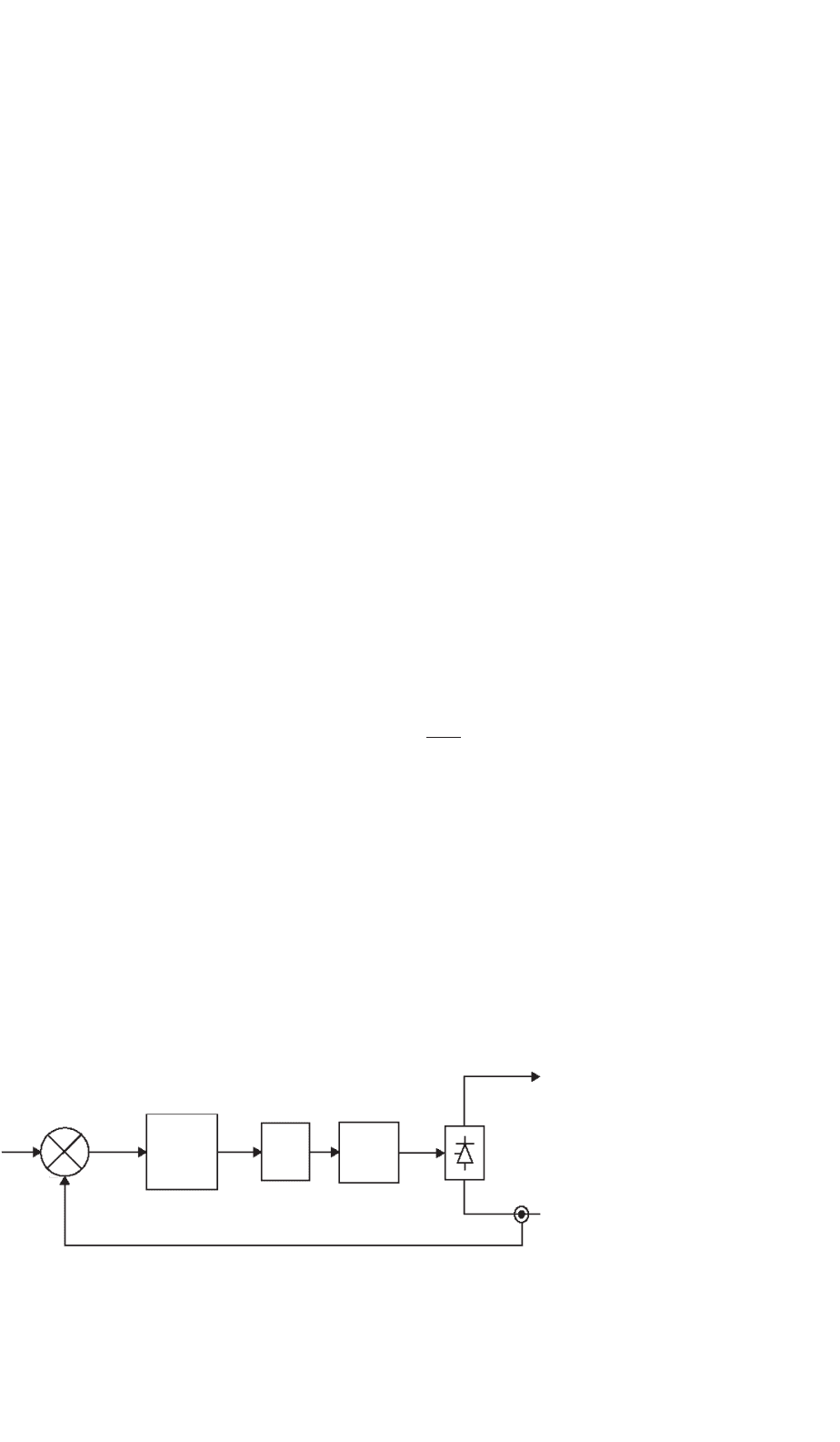
30.4.3.1 Current Control Loops
In conventional HVDC systems, a proportional integral (PI)
regulator is used (Fig. 30.12) for the rectifier current controller.
The rectifier plant system is inherently non-linear and has a
relationship given in Eq. (30.1). For constant I
d
and for small
changes in α, we have
V
d
α
=−V
dor
·sin α (30.4)
It is obvious from Eq. (30.4) that the maximum gain
(V
d
/α) occurs when α = 90
◦
. Thus the control loop
must be stabilized for this operation point, resulting in slower
dynamic properties at normal operation within the range
12–18
◦
. Attempts have been made to linearize this gain and
have met with some limited success. However, in practical
terms, it is not always possible to have the dc link operating
with the rectifier at 90
◦
due to harmonic generation and other
protection elements coming into operation also. Therefore,
optimizing the gains of the PI regulator can be quite ardu-
ous and take a long time. For this reason, the controllers are
782 V. K. Sood
∆I
α
o
+
−
−
I
or
I
d
K/(1 + sT) VCO
from gamma controller
Ring
Counter
MINIMUM
SELECT
I
e
I
d
DCCT
FIGURE 30.13 Current controller at the inverter.
often pre-tested in a physical simulator environment to obtain
approximate settings. Final (often very limited) adjustments
are then made on site.
Other problems with the use of a PI regulator are listed
below:
• It is mostly used with fixed gains, although some possi-
bility for gain scheduling exists.
• It is difficult to select optimal gains, and even then they
are optimal over a limited range only.
• Since the plant system is varying continually, the PI
controller is not optimal.
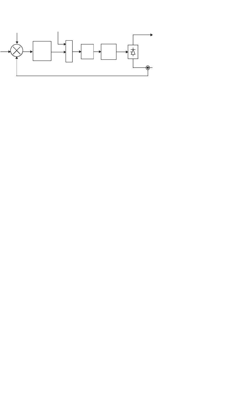
A similar current control loop is used at the inverter
(Fig. 30.13). Since the inverter also has a gamma controller,
the selection between these two controllers is made via a MIN-
IMUM SELECT block. Moreover, in order to bias the inverter
current controller off, a current margin signal I is subtracted
from the current reference I
or
received from the rectifier via a
communication link.
Telecommunication requirements
As was discussed above, the rectifier and inverter current
orders must be coordinated to maintain a current margin of
about 10% between the two terminals at all times, otherwise
there is a risk of loss of margin and the dc voltage could run
down. Although, it is possible to use slow voice communica-
tion between the two terminals, and maintain this margin, the
advantage of fast control action possible with converters may
be lost for protection purposes. For maintaining the margin
during dynamic conditions, it is prudent to raise the current
order at the rectifier first followed by the inverter; in terms
of reducing the current order, it is necessary to reduce at the
inverter first and then at the rectifier.
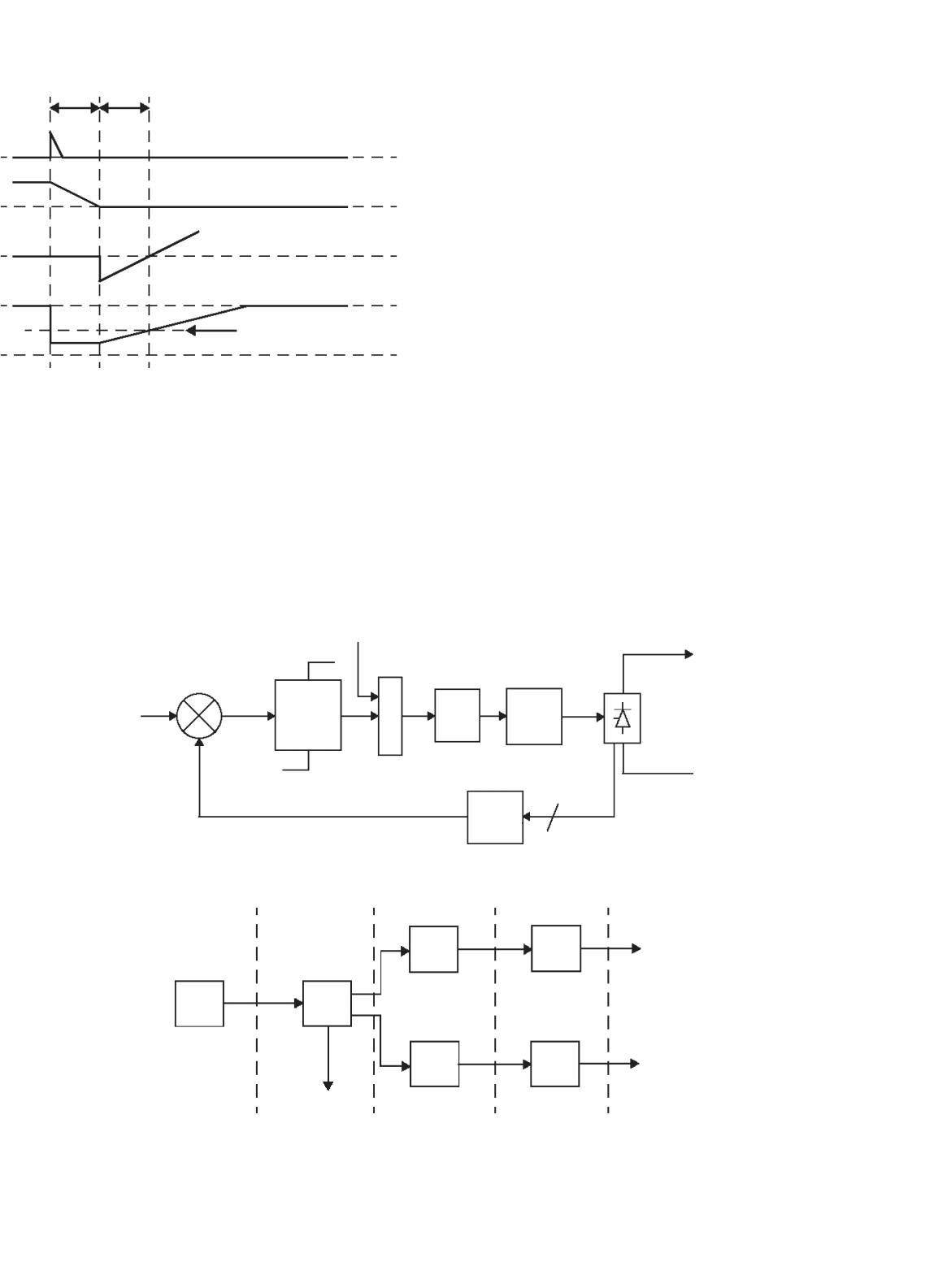
30.4.3.2 Gamma Control Loop
At the inverter end, there are two known methods for the
gamma control loop. The two variants are different only due
to the method of determining the extinction angle:
• Predictive method for the indication of extinction angle
(gamma).
• Direct method for actual measurement of extinction
angle (gamma).
In either case, a delay of one cycle occurs from the indication
of actual gamma and the reaction of the controller to this
measurement. Since the avoidance of a commutation failure
often takes precedence at the inverter, it is normal to use the
minimum value of gamma measured for the 6- or 12-inverter
valves for the converter(s).
1. Predictive method of measuring gamma
The predictive measurement tries to maintain the commu-
tation voltage–time area after commutation larger than a
specified minimum value. Since the gamma prediction is only
approximate, the method is corrected by a slow feedback loop
that calculates the error between the predicted value and actual
value of gamma (one cycle later) and feeds it back.
The predictor calculates continuously, by a triangular
approximation, the total available voltage–time area that
remains after commutation is finished. Since an estimate of
the overlap angle m is necessary, it is derived from a well-
known fact in converter theory that the overlap commutation
voltage–time area is directly proportional to direct current and
the leakage impedance (assumed constant and known) value
of the converter transformer.
The prediction process is inherently of an individual phase
firing character. If no further measures were taken, each valve
would fire on the minimum margin condition. To counter-
act this undesired property, a special firing symmetrizer is
used; when one valve has fired on the minimum margin angle,
the following two or five valves fire equidistantly. (The choice
of either two or five symmetrized valves is mainly a stability
question.)
2. Direct method of measuring gamma
In this method, the gamma measurement is derived from a
measurement of the actual valve voltage. Waveforms of the
gamma measuring circuit are shown in the Fig. 30.14. An inter-
nal timing waveform, consisting of a ramp function of fixed
slope, is generated after being initiated from the instant of zero
anode current. This value corresponds to a direct voltage pro-
portional to the last value of gamma. From the gamma values
of all (either 6 or 12) valves, the smallest value is selected to
30 HVDC Transmission 783
control voltage valve
gamma timing waveform
anode-cathode voltage, valve 1
anode current, valve 1
firing pulse, valve 3
µ
γ
FIGURE 30.14 Waveforms for the gamma measuring circuit [5].
produce the indication of measured gamma for use with the
feedback regulator.
This value is compared to a gamma-ref value and a PI
regulator defines the dynamic properties for the controller
(Fig. 30.15). Inherently, this method has an individual phase
control characteristic. One version of this type of control
implementation overcomes this problem by using a sym-
metrizer for generating equidistant firing pulses. The 12-pulse
from current controller
VCO
Ring
Counter
MIN
SELECT
K/(1 + sT)
MIN
SELECT
12 valve voltages
V
d
α
o
γ
e
γ
meas
γ
ref
+
−
FIGURE 30.15 Gamma feedback controller.
to remote
bipole
Pole
Controls
Value Group
controls
firing
pulses
firing
pulses
Bipole
Controller
Dispatch
Center
P
ref
I
o
α
o
α
o
FIGURE 30.16 Hierarchy of controllers.
circuit generates 12 gamma measurements; the minimum
gamma value is selected and then used to derive the control
voltage for the firing pulse generator with symmetrical pulses.
30.4.4 Hierarchy of DC Controls
Since HVDC controls are hierarchical in nature, they can be
subdivided into blocks that follow the major modules of a
converter station (Fig. 30.16). The main control blocks are:
1. The bipole (master) controller is usually located at one
end of the dc link, and receives its power order from
a centralized system dispatch center. The bipole con-
troller derives a current order for the pole controller
using a local measurement of either ac or dc volt-
age. Other inputs, i.e. frequency measurement, may
also be used by the bipole controller for damping or
modulation purposes. A communication to the remote
terminal of the dc link is also necessary to coordinate
the current references to the link.
2. The pole controller then derives an alpha order for the
next level. This alpha order is sent to both the positive
and negative poles of the bipole.
3. The valve group controllers generate the firing pulses
for the converter valves. Controls also receive measure-
ments of dc current, dc voltage, and ac current into