Power electronic handbook
Подождите немного. Документ загружается.

744 J. M. Carrasco et al.
to consider the type of semiconductor to be used, components
and subsystems.
By using cycloconverters (AC/AC) or frequency converters
based on double frequency conversion, normally AC/DC–
DC/AC, and connected by a DC link, a rapid control of the
active and reactive power can be accomplished along with
a low incidence in the distribution electric grid. The com-
mutation frequency of the power semiconductors is also an
important factor for the control of the wind turbine because
it allows not only to maximize the energy captured from the
wind but also to improve the quality of the energy injected into
the electrical grid. Because of this, the semiconductors required
are those that have a high power limit and allow a high
commutation frequency. The insulated gate bipolar transistor
(IGBTs) are commonly used because of their high breakdown
voltage and because they can bear commutation frequencies
within the range of 3–25 kHz, depending on the power han-
dled by the device. Other semiconductors such as gate turn-off
thyristor (GTOs) are used for high power applications allow-
ing lower commutation frequencies, and thus, worsening not
only the control of the generator but also the quality of the
energy injected into the electric grid. [4, 8, 9, 10, 18].
The different topologies used for a wide-range rotor speed
control are described next. Advantages and disadvantages for
using these topologies, as power electronics is concerned, are:
Advantages:
• Wide-range speed control
•
Simple generator-side converter and control
• Generated power and voltage increased with speed
•
VAR-reactive power control possible
Disadvantages:
• One or two full-power converter in series
•
Line-side inductance of 10–15% of the generated power
• Power loss up to 2–3% of the generated power
• Large DC link capacitors
GB
V
dc
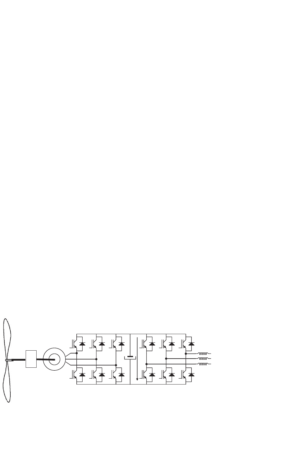
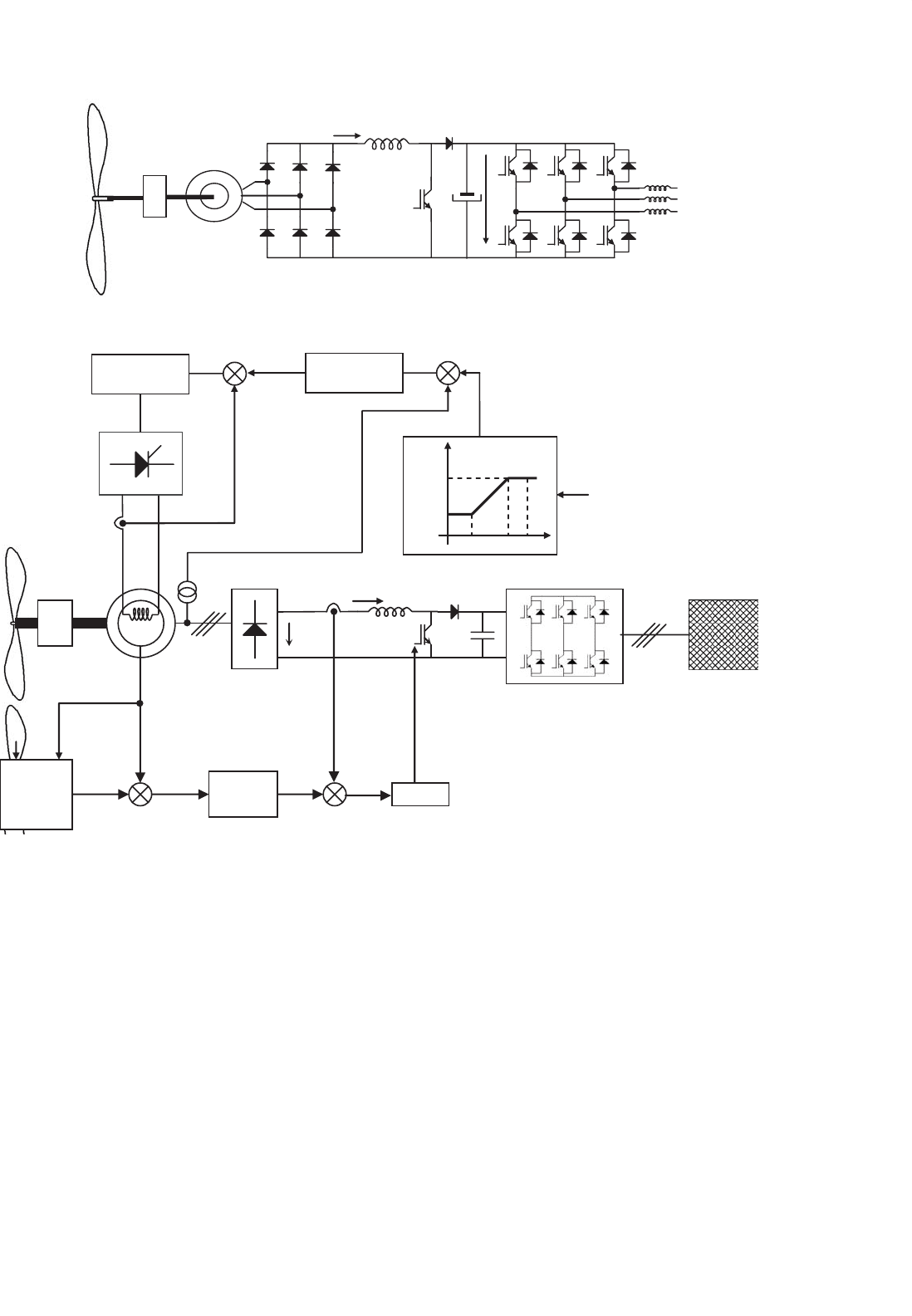
FIGURE 29.10 Double three phase voltage source inverter connected by a DC link used in wind turbine applications.
29.2.2.1 Double Three Phase Voltage Source
Converter Connected by a DC-link
Figure 29.10 shows the scheme of a power condition for a wind
turbine. The three phase inverter on the left side of the power
converter works as a driver controlling the torque generator by
using a vectorial control strategy. The three phase inverter on
the right side of the figure permits the injection of the energy
extracted from the wind into the grid, allowing a control of the
active and reactive power injected into the grid. It also keeps
the total harmonic distortion coefficient as low as possible
improving the quality of the energy injected into the public
grid. The objective of the DC-link is to act as an energy storage,
so that the captured energy from the wind is stored as a charge
in the capacitors and is instantaneously injected into the grid.
The control signal is set to maintain a constant reference to the
voltage of the capacitors battery V
dc
. The control strategy for
the connection to the grid will be described in Section 29.2.3.
The power converter shown in Fig. 29.10 can be used for
a variable speed control in generators of wind turbines, either
for synchronous or asynchronous generators.
29.2.2.1.1 Asynchronous Generator Next to be considered
is the case of an asynchronous generator connected to a wind
turbine. The control of a variable speed generator requires
a torque control, so that for low speed winds the control is
required with optimal tip speed ratio, λ
opt
, to allow maximum
captured wind energy from low speed winds. The generator
speed is adjusted to the optimal tip speed ratio λ
opt
by setting
a reference speed. For high speed winds the pitch or stall reg-
ulation of the blade limits the maximum power generated by
the wind turbine. For low winds it is necessary to develop a
control strategy, mentioned in Section 29.2.
The adopted control strategy is an algorithm for indirect
vector control of an induction machine [3, 6, 7], which is
described next and shown in Fig. 29.11.
29 Wind Turbine Applications 745
L
m
2
2→3
u
u
u
u
u
u
Speed
Controller
GB ASG
grid
−
ω
r
ω
Q
ref
Q
e
ref
−
Optimal tip
Speed ratio
controller
Torque
Controller
Lr2
3
p
−
Current
controller
u
3→2
e
−jη
r
i
Ds
i
Qs
T
r
÷
1/s
i
qse
i
Q
e
Flux
Controller
Current
controller
−
i
i
dse
i
Weakening
block calculation
η
r
i
Rs
i
Ss
i
Ts
i
dse
i
qse
e
−jη
r
PWM
or
SPACE VECTOR
STRATEGY
Voltage Source Inverter
ω
r
D
S
Q
S
d
e
q
e
i
qse
i
dse
i
s
η
r
P
e
1+T
r
s
1
i
m
+
−
ω
r
i
m
++
+
qse
ref
dse
ref
Ds
ref
Rs
ref
Ts
ref
Ss
ref
Qs
ref
ref
dse
ref
m
qse
ref
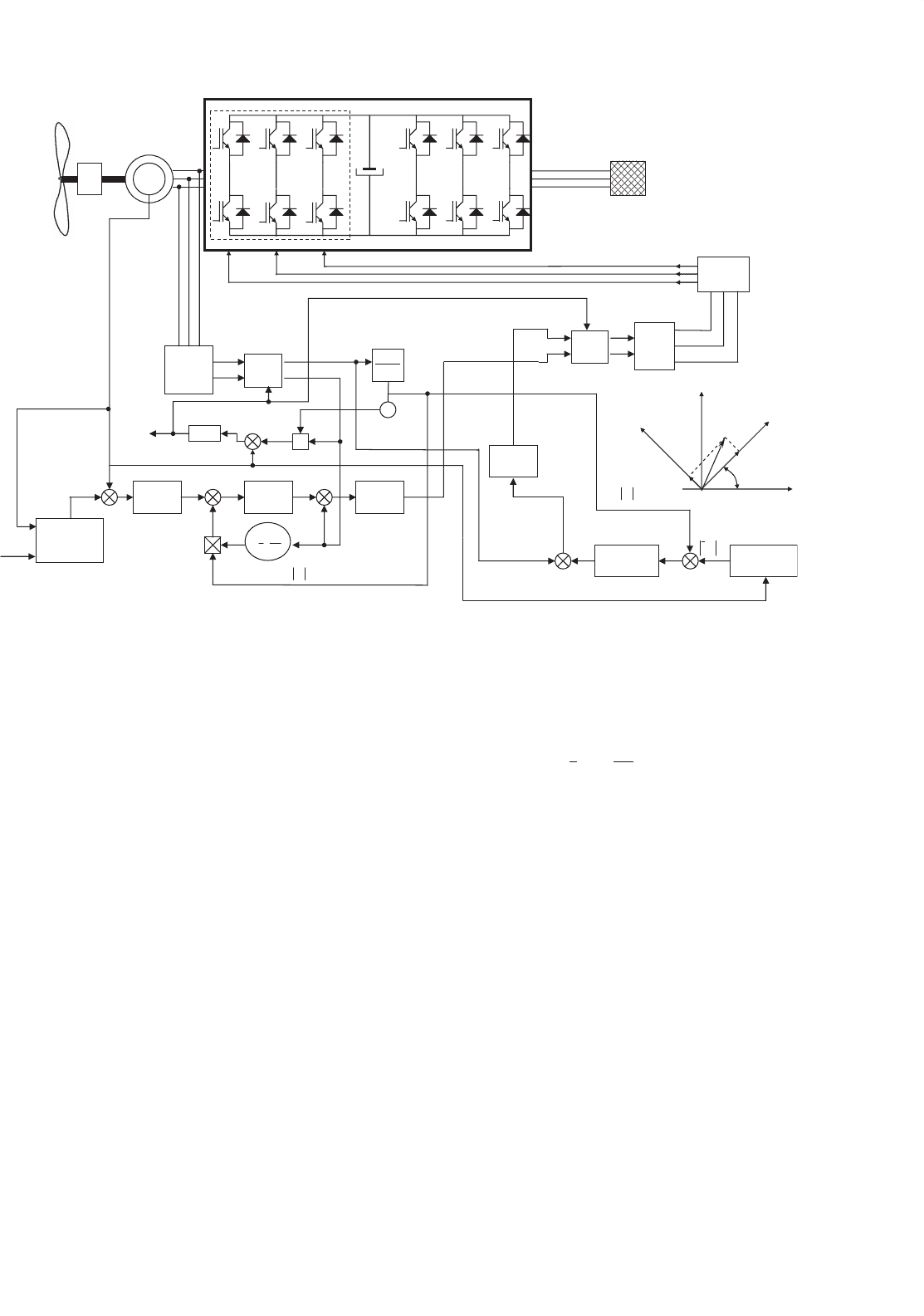
FIGURE 29.11 Schematic of the rotor flux-oriented of a squirrel cage induction generator used in a variable speed wind turbine.
A reference speed, ω
ref
Q
, has been obtained from the control
strategy used in order to achieve optimal speed ratio working
conditions of the wind turbine to capture the maximum energy
from the wind. In Fig. 29.11, the calculation block to obtain
ω
ref
Q
is shown, that is fed by the actual rotor speed, ω
r
, and the
electrical power generated, P
e
, by the asynchronous generator.
Using this ω
ref
Q
and the actual rotor speed, ω
r
, which is mea-
sured by the machine, the reference for the electric torque,
Q
ref
e
, is obtained from the speed regulator which is necessary
to set the reference torque in the machine shaft in order to
achieve the control objectives.
In Fig. 29.11 the induction generator is driven by a voltage-
source pulse width moducation (PWM) inverter, which is
connected by a second voltage-source PWM inverter to the
public grid through a DC link battery capacitors. The out-
put voltage of the inverter is controlled by a PWM technique
in order to follow the voltage references, u
ref
Rs
, u
ref
Ss
, u
ref
Ts
, pro-
vided by the control algorithm in each phase. There are many
types of modulation techniques which are not discussed in
detail here.
A flux model has been used to obtain the angular speed
of the rotor flux and the modulus of magnetizing current,
|i
m
|, that has also been used to calculate the electromagnetic
torque, Q
e
, as shown in Fig. 29.11, using the Eq. (29.9).
Q
e
=
3
2
·p ·
L
2
m
L
r
·
|
i
m
|
·i
qse
(29.9)
The speed controller provides the reference of the torque,
Q
ref
e
, and the torque controller gives the reference value of
the quadrature-axis stator current in the rotor flux-oriented
reference frame i
ref
qse
.
In Fig. 29.11 the field weakening block, used to obtain
the reference value of the modulus of the rotor magnetizing
current space phasor
i
ref
m
, is rotor speed-dependent. This ref-
erence signal is then compared with the actual value of the
rotor magnetizing current,
|
i
m
|
, and the error generated is
used as input to the flux controller. The output of this con-
troller is the direct-axis stator current reference expressed in
the rotor-flux-oriented reference frame i
ref
dse
.
The difference in values of the direct and quadrature-axis
stator current references (i
ref
dse
, i
ref
qse
) and their actual values
(i
dse
, i
qse
) are given as inputs to the respective PI current con-
trollers. The outputs of these PI controllers are values of the
direct and quadrature-axis stator voltage reference expressed
746 J. M. Carrasco et al.
in the rotor-flux-oriented reference frame (u
ref
dse
, u
ref
qse
). After
this they are transformed into the steady reference frame
(u
ref
Ds
, u
ref
Qs
), using the e
−jηr
transformation. This is followed by
the 2 → 3 block and finally, the reference values of the three
phase stator voltage (u
ref
Rs
, u
ref
Ss
, u
ref
Ts
) are obtained. These signals
are used to control the pulse-width modulator, which trans-
forms these reference signals into appropriate on–off switching
signals to command the inverter phase.
29.2.2.1.2 Synchronous Generator When the generator,
used to transform the mechanical energy into electrical energy
in the wind turbine, is a salient-pole synchronous machine
with an electrically excited rotor, the control criteria are the
same as the one applied in the induction generator case, so
as to minimize the angular speed error in order to obtain an
optimum tip speed ratio performance of the wind turbine.
In this section, a drive control based on magnetizing field-
oriented control is described and applied to a wind tur-
bine with a salient-pole synchronous machine. This control
method can be applied to the synchronous generator using
a voltage-source inverter or a cycloconverter as it is shown in
e
jδ
e
jθ
r
2→3
ref
qse
i
−
−
−
PWM
PWM
PWM
sin δ, cos δ
ref
dse
i
ref
qsr
i
ref
dsr
i
ref
Qs
i
ref
Ds
i
ref
Rs
i
ref
Ss
i
ref
Ts
i
Speed
Controller
2→3
e
jθ
r
i
Qs
i
Ds
i
qs
i
ds
Abs
÷
÷
λ
m
÷
λ
md
λ
mq
sin δ
cos δ
+
+
i
exc
i
r
i
s
i
t
GB
grid
1/s
ω
r
θ
r
−
ω
r
ref
Q
ω
Flux
Controller
ref
m
λ
−
Current
controller
−
÷
ref
e
Q
m
λ
cos δ
ref
exc
i
i
exc
i
qs
i
ds
q
Q
s
d
e
L
md
i
exc
δ
θ
r
i
m
i
s
q
e
D
s
d
Flux
Estimator
Optimal tip
Speed ratio
controller
−
P
e
ref
exc
i
i
Rs
i
Ss
i
Ts
Flux
characteristic
function
i
exc
L
md
i
ds
PI
PI
PI
i
exc
i
exc
S
+
+
+
+
+
+
λ
m
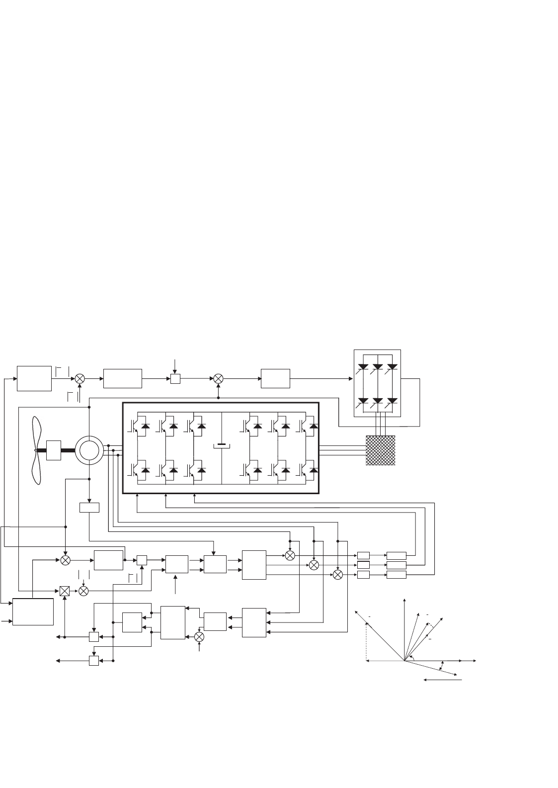
FIGURE 29.12 Block diagram of a field-oriented control of a salient-pole synchronous machine used in wind turbine applications.
Figs. 29.10 and 29.13 respectively, using the same block control
diagram.
In both cases, a controllable three-phase rectifier sup-
plies the excitation winding on the rotor of the synchronous
machine. As it is well-known, the cycloconverter is a fre-
quency converter which converts power directly from a fixed
frequency to a lower frequency. Each of the motor phases is
supplied through a three-phase transformer, an antiparallel
thyristor bridge, and the field winding is supplied by another
three-phase transformer and a three-phase-rectifier using the
bridge connection.
In the control block described in Fig. 29.12, the rotor speed
and monitored current have been used in order to control the
relationship between the magnetizing flux and currents of the
machines by modifying the voltages of the power converter
and the excitation current in the field winding.
The reference rotor speed, ω
ref
Q
, and the measured rotor
speed, ω
r
, are compared and the error is introduced into the
speed controller. The output voltage is proportional to the
electromagnetic torque PI, of the synchronous machine and
the reference torque, Q
ref
e
, is obtained. Dividing the reference
torque by the modulus of the magnetizing flux-linkage space
29 Wind Turbine Applications 747
Control
Block
ω
Q
ref
i
Rs
i
Ss
i
exc
i
TS
SG
ω
r
P
e
Optimum
speed ratio
calculation
block
grid
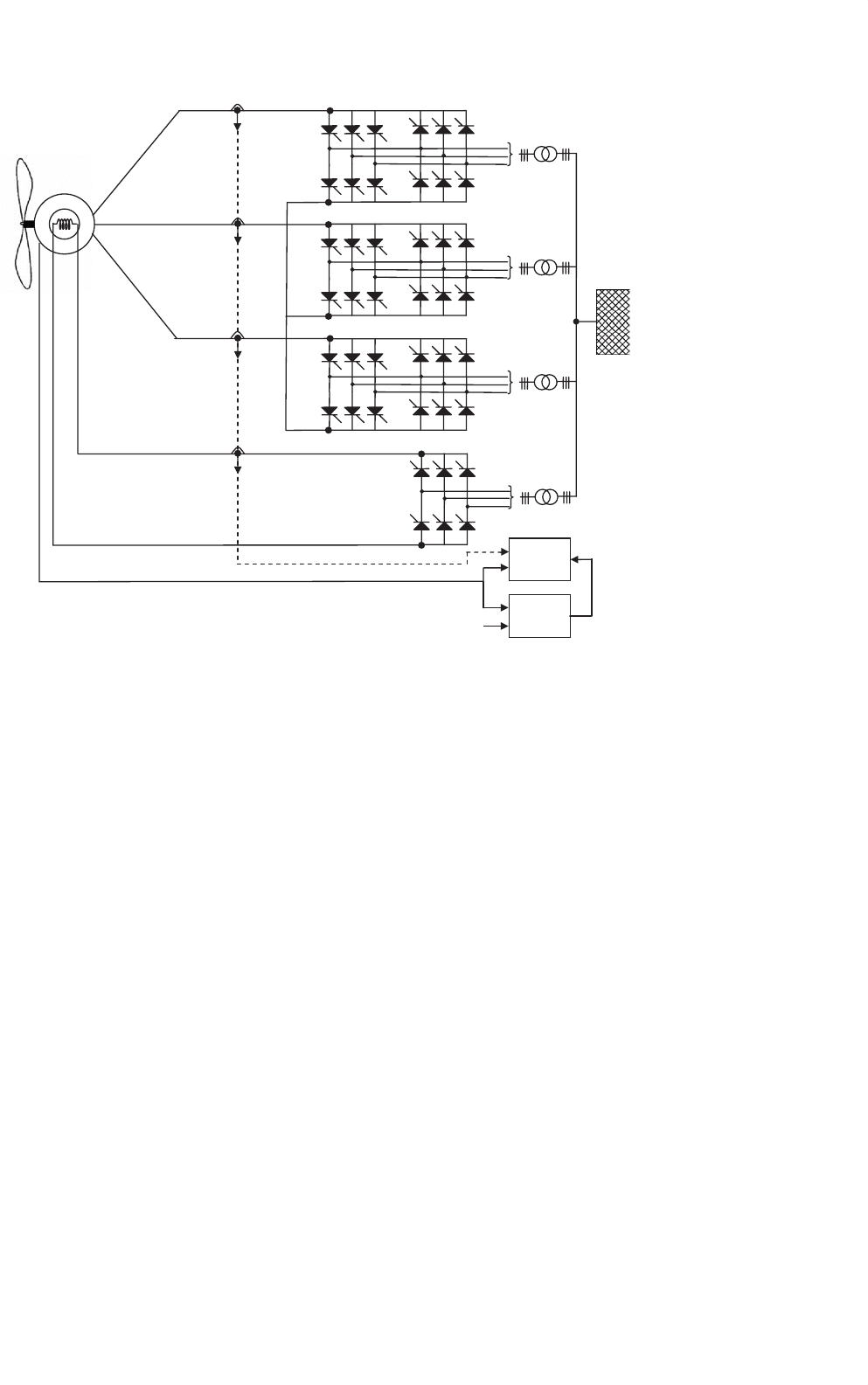
FIGURE 29.13 Schematic of the cycloconverter synchronous generator used in variable speed wind turbines.
phasor
|
λ
m
|
, the reference value of the torque-producing stator
current,
|
λ
m
|
, component is obtained.
Using a characteristic function of the magnetizing flux ref-
erence and the actual rotor speed, ω
r
, the magnetizing flux
reference is obtained,
λ
ref
m
. Below base speed, this function
yields a constant value of the magnetizing flux reference, λ
ref
m
;
above base speed, this flux is reduced. The magnetizing flux
controller,
¯
λ
m
, is introduced and compared with the esti-
mated magnetizing flux of the synchronous machine,
λ
ref
m
,
obtaining the error, which is fed into the flux controller as
shown in Fig. 29.12. The flux controller maintains the magne-
tizing linkage flux to a pre-set value independent of the load.
As an output of this controller the reference excitation current,
i
ref
exc
is obtained.
The value of the reference magnetizing stator current, i
ref
exc
,
is obtained using a steady state in which there is no reactive
current drawn from the stator [3]. In this case the power fac-
tor is unity and the stator current value is the optimal. The
zero reactive power condition can be fulfilled by controlling
the magnetizing current stator component that is shown in
Fig. 29.12.
The stator current components (i
ref
dsc
, i
ref
qse
) are first trans-
formed into the stator current components established in the
rotor reference frame (i
ref
dsr
, i
ref
qsr
). After these components are
transformed into the stationary-axes current components by a
similar transformation, but taking into account that the phase
displacement between the stator direct axis of the rotor is
θ
r
. The obtained two-axis stator current references (i
ref
Qs
, i
ref
Ds
),
are transformed into the three phase stator current references
(i
ref
Rs
, i
ref
Ss
, i
ref
Ts
) by the application of the three phase to two phase
transformation. The reference stator currents are compared
with their respective measured currents, and their errors are
fed into the respective stator current controllers.
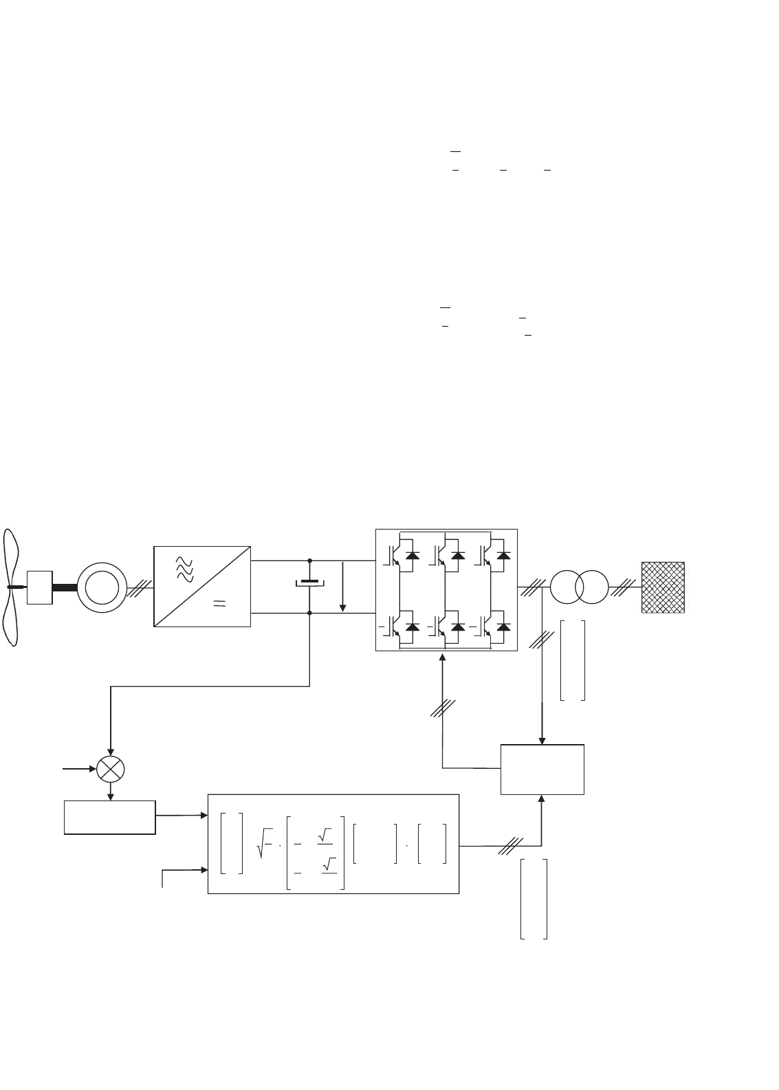
29.2.2.2 Step-up Converter and Full Power Converter
An alternative for the power conditioning system of a wind
turbine is to choose a synchronous generator and a three phase
diode rectifier, as shown in Fig. 29.14. Such a choice is based
on low cost compared with an induction generator connected
to a voltage source inverter used as a rectifier. When the speed
of the synchronous generator alters, the voltage value on the
DC-side of the diode rectifier will change. A step-up chopper
is used to adapt the rectifier voltage to the DC-link voltage of
the inverter, see Fig. 29.14. When the inverter system is ana-
lyzed, the generator/rectifier system can be modeled as an ideal
current source. The step-up chopper used as a rectifier utilizes
748 J. M. Carrasco et al.
i
dc
C
dc
V
dc
GB
L
DC
L
AC
FIGURE 29.14 Step-up converter in the rectifier circuit and full power inverter topology used in wind turbine applications.
Speed
Controller
−
ω
r
ω
Q
ref
ω
ref
−
PWM
Grid
V
av
V
av
≈ cte
Optimal tip
Speed rotor
Controller
P
e
ref
dc
i
ref
r
ω
i
L
i
dc
C
dc
ω
r
Regulator
Regulator
V
st
V
st
i
exc
ref
exc
i
ω
r
min
ω
r
rate
ω
r
max
V
st
ω
r
ω
r
−
+
−
+
SG
+
+
GB
Excitation charasteristic
V
st
min
V
st
max
ref
α
FIGURE 29.15 Control block diagram of a step-up converter in the rectifier circuit and full power inverter used in wind turbine applications.
a high switching frequency so the bandwidth of these com-
ponents is much higher than the bandwidth of the generator.
The generator/rectifier current is denoted as i
dc
and is inde-
pendent of the value of the DC-link voltage. The inductor of
the step-up converter is denoted as LDC. The capacitor of the
DC-link has the value C
dc
. The inductors on the AC-side of
the inverter have the inductance L
AC
. The three-phase voltage
system of the grid has phase voltages e
R
, e
S
, and e
T
and the
phase currents are denoted as i
Rg
, i
Sg
, and i
Tg
. The DC-link
voltage value is denoted as V
dc
.
The control system, shown in Fig. 29.15, is based on
the measurement of the rotor speed ω
r
of the synchronous
generator by means of a speed transducer. This value is com-
pared with the reference rotor speed obtained by the control
algorithm of the variable speed wind turbine used in the appli-
cation in order to achieve optimal speed ratio, and therefore,
to capture the maximum energy from the wind.
The objective of the synchronous machine excitation system
is to keep the stator voltage V
st
following the excitation char-
acteristic of the generator, shown in Fig. 29.15. This excitation
characteristic is linear in the range of the minimum of the rotor
speed ω
min
r
and the rated value of the rotor speed ω
rate
Q
. Outside
this range, the stator voltage is saturated to V
min
st
or V
max
st
.
For rotor speeds ω
r
in the range between ω
min
r
and ω
rate
r
, the
29 Wind Turbine Applications 749
control is carried out using an inductor current i
dc
propor-
tional to the shaft torque of the generator. Above the rated
rotor speed, this current is proportional to the power because
the stator voltage V
st
is constant.
29.2.2.3 Grid Connection Conditioning System
Injection into the public grid is accomplished by means of
PWM voltage source interver. This requires the control of the
current of each phase of the inverter, as shown in Fig. 29.16.
There are several methods of generating the reference cur-
rent to be injected into any of the phases of the inverter.
A very useful method to calculate this current was proposed
by Professor Akagi [19], that is applied to the active power
filters referred to as “Instantaneous Reactive Power Theory.”
The control block shown in Fig. 29.16 is based on the compar-
ison of the actual capacitor array voltage V
dc
with a reference
voltage V
ref
dc
. Subtracting the actual capacitor array voltage
V
ref
dc
from the reference voltage V
ref
dc
, the error signal volt-
age is obtained. This error signal is fed into a compensator,
usually a PI compensator, that transforms the output to an
active instant power signal that, after being injected into the
electric grid, is responsible for the error of the regulator of the
voltage in the capacitor array to be zero.
grid
V
dc
u
v
w
Control
Circuit
Regulator
q
ref
= 0
V
dc
ref
−
=
ref
ref
sg
ref
rg
q
ref
p
ref
e
a
−e
b
e
b
e
a
i
i
i
−1
tg
2
3
2
1
2
3
2
1
01
3
2
ref
tg
ref
sg
ref
rg
i
i
i
i
tg
i
sg
i
rg
u
uvw
v
w
V
dc
p
ref
GB
+
FIGURE 29.16 Control block diagram of the grid connection conditioning system.
Transformation of the phase voltage e
rg
, e
sg
, and e
tg
into
the α–β orthogonal coordinates is given by the following
expression:
e
α
e
β
=
2
3
·
1 −1/2 −1/2
0
√
3/2 −
√
3/2
·
e
rg
e
sg
e
tg
(29.10)
Using the inverse transformation equations from the control
algorithm [19] and the reference of real power of the capacitor
array, it is possible to derive the phase sinusoidal reference
current to be injected by the converter into the grid.
i
ref
rg
i
ref
sg
i
ref
tg
=
2
3
·
10
−1/2
√
3/2
−1/2 −
√
3/2
·
e
α
e
β
−e
β
e
α
−1
·
p
ref
q
ref
(29.11)
As can be seen in the above equation, the reference of the
reactive power appears which is normally set at zero so that
the current is being injected into the public grid with unity
power factor.
There is another type of wind energy extraction system
where the objective is to compensate the reactive power
750 J. M. Carrasco et al.
generated by non-linear loads of the grid. In this case, the
reactive reference power is set to the corresponding value,
for either reactive or capacitive power factor “leading or
lagging.”
29.2.3 Rotor Connected Power Conditioner for
Variable Speed Wind Turbines
As it was introduced before, variable speed can also be obtained
by slip change of induction generator using a wound rotor
machine.
Since it is necessary to have an electric connection to the
rotor winding, rotation is achieved by using a slip ring. The
power delivered by the rotor through the slip rings is equal
to the product of the slip by the electrical power that flows
into the stator P
S
, Eq. (29.12). This is the so-called “slip
power” P
slip
.
P
slip
= s ·P
S
(29.12)
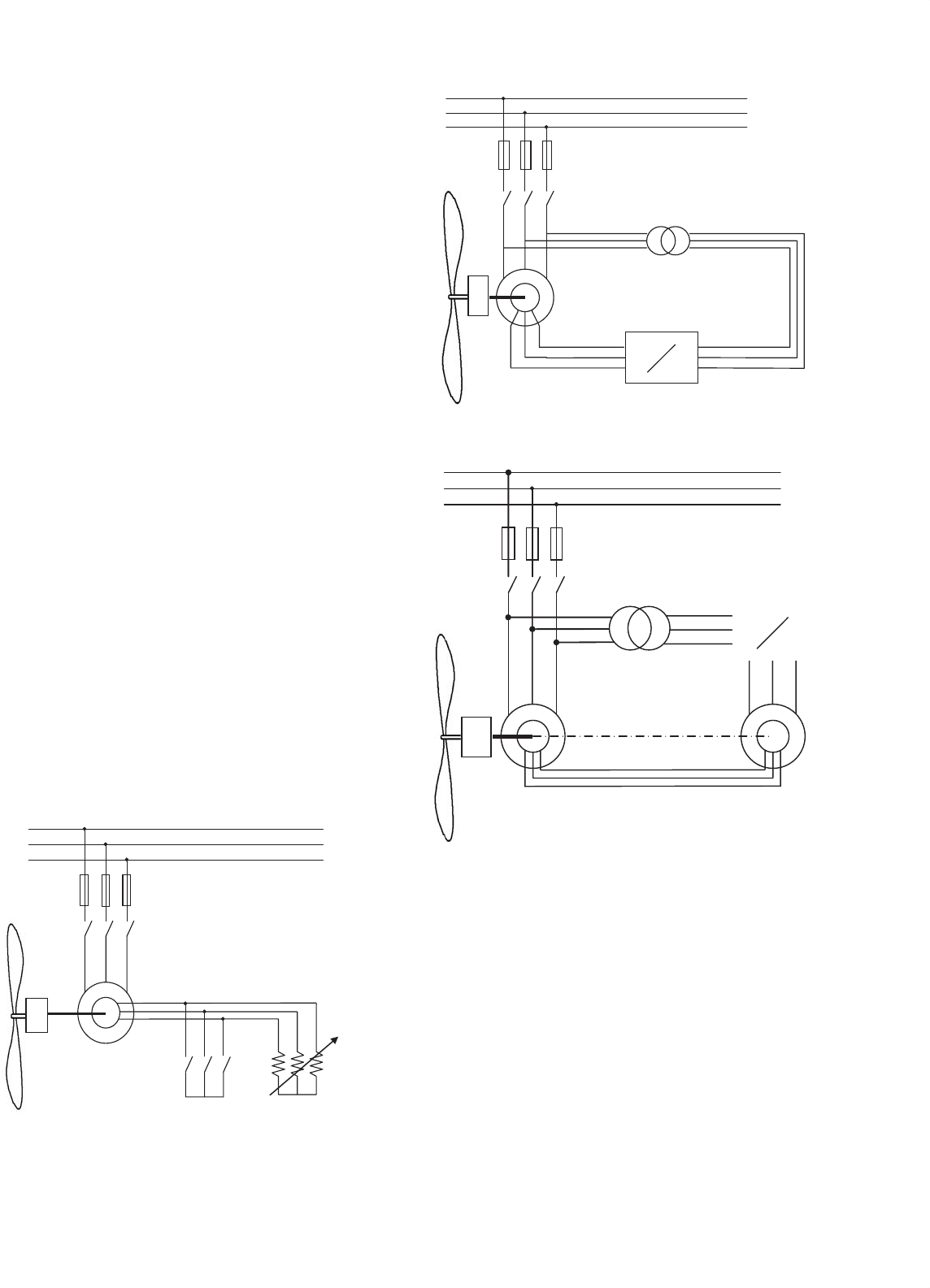
The slip power can be handled as follows:
• It can be dissipated in a resistor (Fig. 29.17).
• Using a single doubly fed scheme, the slip power is
returned to the electrical grid or to the machine stator
(Fig. 29.18).
• Using a cascaded scheme. This is accomplished by con-
necting a second machine. Part of the power is transferred
as mechanical power through the shaft, and the other
part is transferred to the grid by a power converter
(Fig. 29.19).
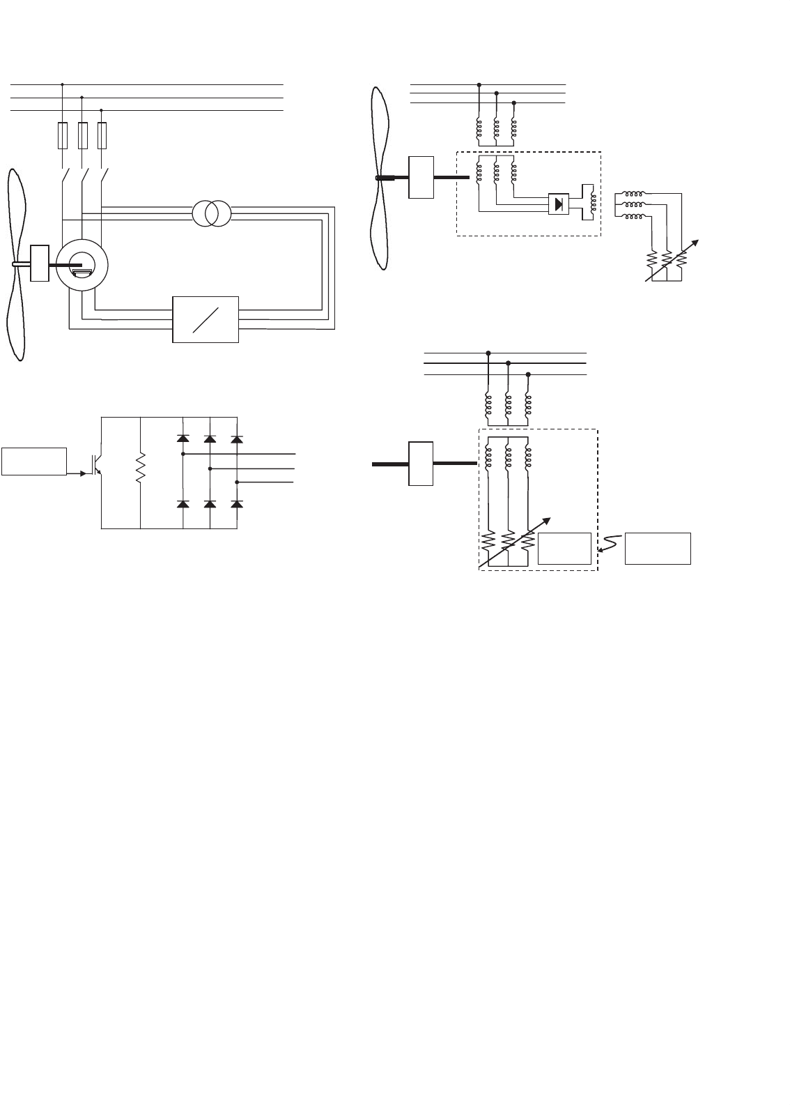
•
A single frame cascaded or brushless doubly fed induction
machine [20] can be used in the same way as before, but
using only one machine instead of two (Fig. 29.20).
Fuses
a
b
c
Variable
resistor
Short-circuit bar
GB
FIGURE 29.17 Slip power dissipation in a resistor.
Fuses
Transformer
c
b
a
c’
b’
a’
AC
AC
sf
1
f
1
f
1
GB
FIGURE 29.18 Single doubly fed induction machine.
AC
AC
GB
FIGURE 29.19 Wound rotor cascaded induction machines.
29.2.3.1 Slip Power Dissipation
Figure 29.17 shows a system in which the power delivered by
the rotor is dissipated in a resistor.
The variable resistor can be substituted by the power con-
verter in Fig. 29.21. The power converter controls the power
delivered to the resistor using an uncontrolled rectifier and a
parallel DC–DC chopper. This design has the disadvantage of
the current having a higher harmonic content. This is caused
by the rectangular rotor current waveform in the case of a
three phase uncontrolled rectifier. This disadvantage can be
avoided using a six IGBT’s controlled rectifier, however this
topology increases the cost significantly.
29 Wind Turbine Applications 751
Fuses
Transformer
c
b
a
c’
b’
a’
AC
AC
sf
1
f
1
f
1
GB
FIGURE 29.20 Brushless doubly fed induction machine.
CONTROL
CIRCUIT
a
b
c
FIGURE 29.21 Variable resistor using a power converter.
The variation of the rotor resistance is not a recommended
technique due to the high copper losses in the regulation resis-
tance and so, the generator system efficiency is lower. It only
can be efficient within a very narrow range of the rotor speed.
Another disadvantage is that this technique is applicable only
to wound-rotor machines and so, slip rings and brushes are
needed. In order to solve this problem some brushless schemes
are proposed. A solution is to use a rotor auxiliary winding
which couples the power to an external variable resistor. The
scheme can be observed in Fig. 29.22.
Another solution is to dissipate the energy within a resistor
placed in the rotor as it is shown in Fig. 29.23. This method
is currently used in generators for wind conversion systems,
but as the efficiency of the system decreases with increasing
the slip, the speed control is limited to a narrow margin. This
scheme includes the power converter and the resistors in the
rotor. Trigger signals to the power switches are accomplished
by optical coupling.
29.2.3.2 Single Doubly Fed Induction Machine
In Fig. 29.18 the connection scheme shows that slip power
is injected into the public grid by a power converter and a
transformer. The power converter changes the frequency and
Stator
winding
Rotor main
winding
Rotor auxiliary
winding
ROTOR
Variable
resistor
GB
FIGURE 29.22 Slip power dissipation in an external resistor using
brushless machine.
CONTROL
CIRCUIT
Stator
winding
Rotor
winding
FIRING
UNIT
OPTICAL
COUPLING
Variable
resistor
ROTOR
GB
FIGURE 29.23 Slip power dissipation in an internal resistor using
brushless machine.
controls the slip power. In some cases a transformer is used
due to public grid voltages which can be higher than rotor
voltages.
Disregarding losses, the simplified scheme of Fig. 29.24
shows real power flux in all different connection points of
the diagram. In this figure, the electrical power in the stator
machine P
S
, the mechanical power (1 − s) · P
S
, and the slip
power and power converter s ·P
S
are represented.
In generation mode, the power is positive when the arrow
direction shown in Fig. 29.24 is considered. The power handled
on the power converter depends on the sign of the machine
slip. When this slip is positive, i.e. subsynchronous mode of
operation, the slip power goes through the converter from the
grid to the rotor of the machine. On the other hand, when
the slip is negative, i.e. hypersynchronous mode of operation,
the slip power comes out of the rotor to the power converter.
Since the slip power is the real power through the converter,
this power is determined directly by the maximum slip or by
the speed range of the machine. For instance, if the speed range
752 J. M. Carrasco et al.
(1−s)
.
P
s
(1−s)P
s
s
.
P
s
s
.
P
s
P
s
POWER
CONVERTER
FIGURE 29.24 Simplified scheme of a single doubly fed induction
machine.
used is 20% of the synchronous speed, the power rating of the
converter is 20% of the main power.
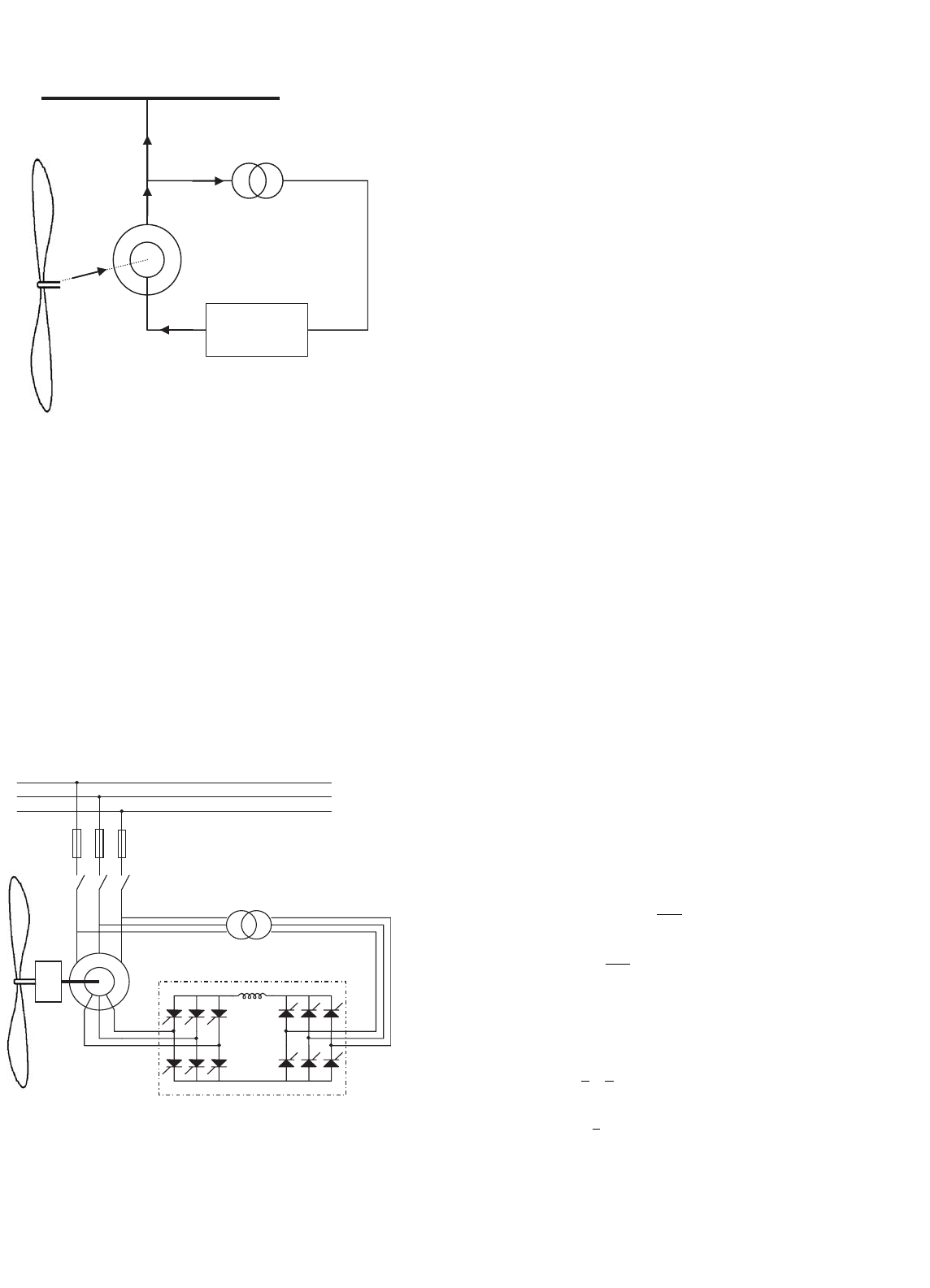
29.2.3.3 Power Converter in Wound-rotor Machines
The power converter used in wound-rotor machines can be a
force-commutated converter connected to a line-commutated
converter by an inductor as shown in Fig. 29.25. In this case,
the power can only flow from the rotor to the grid, and the
induction generator works above synchronous speed. Main
disadvantages of this scheme are a low power factor and a high
content of low frequency harmonics whose frequency depends
on the speed.
Fuses
Transformer
c
b
a
c’
b’
a’
Power converter cascade
GB
FIGURE 29.25 Single doubly fed induction machine with a force-
commutated converter connected to a line-commutated converter.
Since the feeding frequency of the rotor is much lower than
the grid’s, a cycloconverter, as shown in Fig. 29.26, can be
used. In this case the controllability of the system is greatly
improved. The cycloconverter is an AC–AC converter based
on the use of two three-phase thyristor bridges connected in
parallel, one for each phase. This scheme allows working with
speed above and below the synchronous speed.
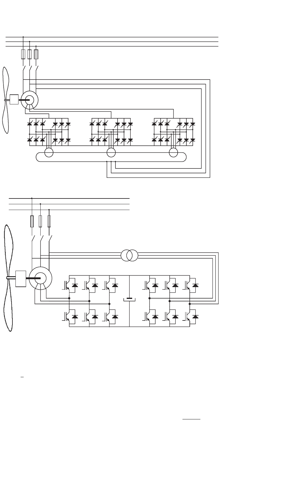
The two schemes mentioned before (Figs. 29.25 and
Fig. 29.26) are based on line switched converters. A disad-
vantage of this scheme is that voltages in the rotor decrease
when the machine is working in frequencies close to the syn-
chronous frequency. This fact makes the line-commutated
converter not to commute satisfactorily, and we need to
use a forced-commutated converter. Also, when a forced-
switched converter is used, quality of the voltage and current
injected into the public grid is improved. The forced-switched
power converter scheme is shown in Fig. 29.27. The converter
includes two three-phase AC–DC converters linked by a DC
capacitor battery. This scheme allows, on one hand, a vec-
tor control of the active and reactive power of the machine,
and on the other hand, a decrease by a high percentage of
the harmonic content injected into the grid by the power
converter.
29.2.3.4 Control of Wound-rotor Machines
The vector control of the rotor flux can be accomplished very
easily in a wound-rotor machine. Power converters that can
be used for vector control applications are either a controlled
rectifier in series with an inverter or a cycloconverter.
In this system, the slip power can flow in both directions,
from the rotor to the grid (subsynchronous) or from the grid
to the rotor (hyper-synchronous). In both working modes, the
machine must be working as a generator. When the speed is
hyper-synchronous, the converter connected to the rotor will
work as a rectifier and the converter connected to the grid as
an inverter, as was deduced before from Fig. 29.24.
The wound-rotor induction machine can be modeled as
follows (see nomenclature page):
u
S
= R
S
·i
S
+
dλ
S
dt
(29.13)
u
r
= n
2
·R
r
·i
r
+
dλ
r
dt
−j · ω
r
·λ
r
(29.14)
λ
S
= L
S
·i
S
+n ·L
m
·i
r
(29.15)
λ
r
= n
2
·L
S
·i
r
+n ·L
m
·i
S
(29.16)
Q
e
=
3
2
·
ρ
2
·I
m
λ
r
·i
∗
r
(29.17)
P
S
=
3
2
·R
e
u
S
·i
∗
s
(29.18)
29 Wind Turbine Applications 753
Transformer
a
b
c
GB
Fuses
FIGURE 29.26 Single doubly fed induction machine with a cycloconverter.
Fuses
Transformer
c
b
a
c’
b’
a’
GB
FIGURE 29.27 Single doubly fed induction machine with two fully controlled AC–DC power converters.
Q
S
=
3
2
·I
m
u
S
·i
∗
S
(29.19)
In the induction machine model, rotor magnitudes, the
rotor voltage u
r
, the rotor flux λ
r
, and the rotor current i
r
are referred to the stator, and so, the rotor voltage u
r
, the
rotor flux λ
r
, and the rotor current i
r
are defined as:
u
r
= n ·u
r
·e
j·θ
r
(29.20)
λ
r
= n ·λ
r
·e
j·θ
r
(29.21)
i
r
=
i
r
·e
j·θ
r
n
(29.22)