Power electronic handbook
Подождите немного. Документ загружается.


724 S. K. Mazumder
i
r
=
V
dc
ωL
r
B
n
sin
ωt +φ −
π
2
(considering only the
fundamental component)
The current injected by the APF is
i
ac
= (S
a
−
1
2
)i
r
(28.9a)
i
ac
=
V
dc
ωL
r
B
2
n
sin(ωt +φ) sin
ωt +φ −
π
2
(28.9b)
i
ac
=
V
dc
2ωL
r
B
2
n
cos
π
2
−cos
2ωt +2φ −
π
2
(28.9c)
In order to reduce the 2nd harmonic in the input current to
zero, i
ac
= I
ac
V
dc
2ωL
r
B
2
n
cos
2ωt +2φ −
π
2
=
V
o
I
o
V
dc
cos(2ωt −θ)
(28.10a)
which yields
B
n
=
√
2ωL
r
V
o
I
o
V
dc
(28.10b)
φ =
π
4
−
θ
2
(28.10c)
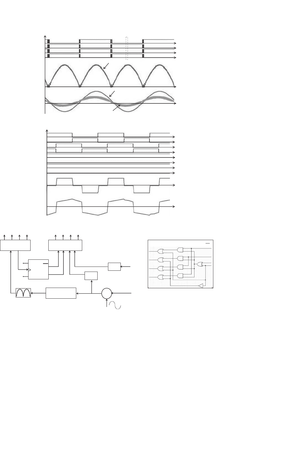
DC/AC Converter
A two-stage dc/ac converter (shown in Fig. 28.10) comprises
a soft-switched phase-shifted synchronized pulse-width mod-
ulation (SPWM) multilevel HF inverter and a line-frequency
switched ac/ac cycloconverter. The multilevel arrangement of
the HF inverter switches reduces the voltage stress and the
cost of the high-frequency semiconductor switches. The ac/ac
stage comprises a single-phase cycloconverter and an output
LC filter. The cycloconverter has two bidirectional switch pairs
Q
1
and Q
2
and Q
3
and Q
4
for a single-phase output. In order
to achieve a 60-Hz sine-wave ac at the output, the sine wave
modulation can be performed either on the HF inverter or on
the cycloconverter. Therefore, two different modulation strate-
gies are possible for the dc/ac inverter. Both schemes result in
the soft switching of the HF inverter while the cycloconverter
is hard switched.
In the first modulation scheme the cycloconverter switches
follow SPWM, while the HF inverter switches are switched
at fixed 50% duty pulse. The HF inverter switches in this
scheme undergo zero-voltage turn-on. In the second mod-
ulation scheme, the switches of the multilevel HF inverter
follow SPWM and the cycloconverter switches are switched
based on the power-flow information. Unlike the first modu-
lation scheme, which modulates the cycloconverter switches at
high frequency, in the second modulation scheme, cyclocon-
verter operates at line frequency. The switches are commutated
at high frequency only when the polarities of output cur-
rent and voltage are different. Usually this duration is very
small and therefore, the switching loss of the ac/ac cyclocon-
verter is considerably reduced compared to the conventional
control method. Therefore, the heat-sinking requirement of
the cycloconverter switches is significantly reduced. The HF
inverter switches in this scheme undergo zero-current turn-off.
Control signals for the second modulation scheme are shown
in Fig. 28.10.
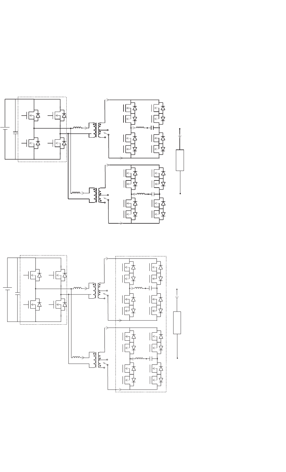
B. Universal Power Conditioner [19]
2
This approach achieves a direct power conversion and does
not require any intermediate energy storage components.
As shown in Fig. 28.11, the final approach has a HF inverter
followed by a HF transformer and a forced cycloconverter.
Switches (Q1–Q4) on the primary of the HF transformer are
sine-wave modulated to create a HF three-level ac voltage. The
three-level ac at the output of the HF transformer is converted
to 60/50 Hz line-frequency ac by the cycloconverter and the
LC filter. For an input of 30 V, the transformation ratio of
the HF transformer is calculated to be N = 13. Fabrication
of a 1:13 transformer is relatively difficult. Furthermore, high
turns ratio yields enhanced secondary leakage inductance and
secondary winding resistance, which result in measurable loss
of duty cycle and secondary copper losses, respectively. Higher
leakage also leads to the higher voltage spike, which added to
the high nominal voltage of the secondary that necessitate the
use of high-voltage power devices. Such devices have higher
on-resistance and slower switching speeds.
Therefore, a combination of two transformers and two
cycloconverters on the secondary side of the HF transformer is
identified to be an optimum solution. For an input voltage in
the range of 30–42 V, we use N = 6.5, while for an input volt-
age above 42 V, we use N = 4.3. To change the transformation
ratio of the HF transformer, we use a single-pole-double-throw
(SPDT) relay, as shown in Figs. 28.11a, b. Such an arrange-
ment not only improves the efficiency of the transformer but
also significantly improves the utilization of the cycloconverter
switches for operation at 120/240 V ac and 60/50 Hz. For 120 V
ac output, the two cycloconverter filter capacitors are paral-
leled (as shown in Fig. 28.11a) while for 240 V ac output, the
voltage of the filter capacitor are connected in opposition (as
shown in Fig. 28.11b).
Modes of Operation
In this section, we discuss the modes of operation of the
inverter in Fig. 28.11 for 120 V ac output and for an input
voltage in the range of 42–60 V (i.e. N = 4.3). The modes
of operation below 42 V (i.e. N = 6.5) remains the same.
2
University of Illinois, Chicago secured the first position among U.S.A
and 3rd position among worldwide university competition for this topol-
ogy, which was developed as a part of 2005 IEEE Future Energy Challenge
Competition.
28 Fuel-cell Power Electronics for Distributed Generation 725
Q1
Q2
Q4
Q3
Modulating Signal for the HF Inverter
Inverter Output Voltage
Inverter Output Current
(a)
Q1
Q2
Q4
Q3
S1
S4
S2
S3
V
pri
I
pri
Q1
Q2
Q4
Q3
Modulating Signal for the HF Inverter
Inverter Output Voltage
Inverter Output Current
Q1
Q2
Q4
Q3
S1
S4
S2
S3
V
pri
I
pri
(b)
V
0
G
c
= K
p
+K
i
/s
UC3895
S
1
S
2
S
3
S
4
Q
1
Q
2
Q
3
Q
4
1
1
V
ref
+
–
ZCD
ZCD
Logic Operator
i
0
J
K
Clk
q
q
p
C
p
V
q
q
p
C
p
V
Q
1
Q
4
Q
3
Q
2
Logic Operator
(c)
FIGURE 28.10 (a) Schematic waveforms for the inverter operation; (b) schematic waveforms for the HF inverter; and (c) overall control scheme
for the HF inverter.
Figure 28.10 shows the waveforms of the five operating
modes of the phase-shifted HF inverter and a positive pri-
mary and a positive filter-inductor current. Modes 2 and
4 show the zero-voltage switching (ZVS) turn-on mech-
anism for switches Q
3
and Q
4
, respectively. Unlike con-
ventional control scheme for cycloconverter [13], which
modulates the switches at high frequency, the proposed
cycloconverter operates at line frequency. The switches are
commutated at high frequency only when the polarities of
the output current and voltage are different [13]. For unity
power-factor operation, this duration is negligibly small and
therefore, the switching loss of the ac/ac cycloconverter is
considerably reduced compared to the conventional control
method [14, 16].
Five modes of the PES operation are discussed for positive
primary current. A set of 5 modes exists for a negative primary
current as well. A similar set of five modes of operation for the
240 V ac exists [19] for input voltage above 42 V (N = 4.5).
726 S. K. Mazumder
Again, the mode of operation for input voltage below 42 V
(N = 6.5) remains the same.
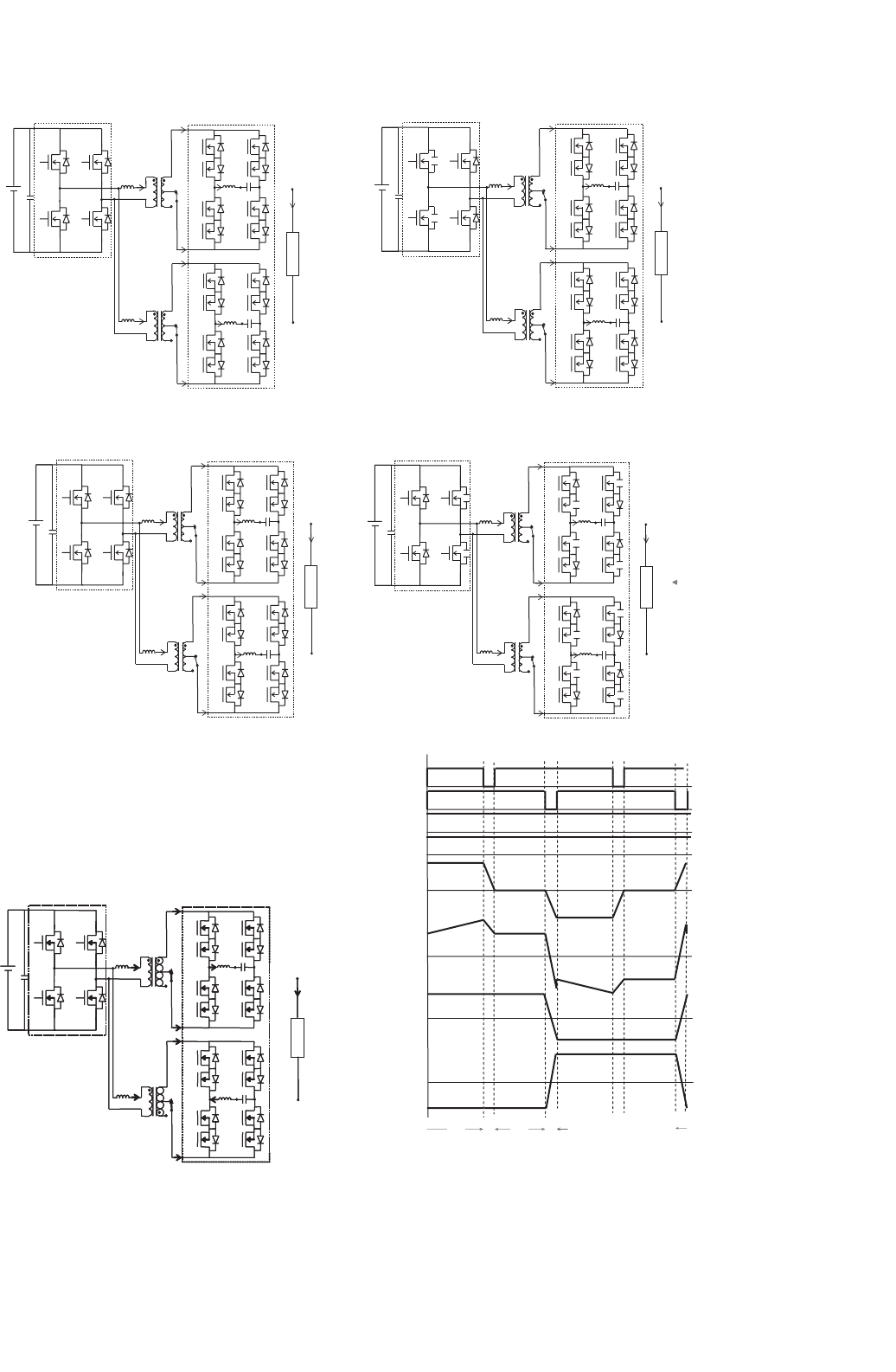
Mode 1 (Fig. 28.12a): During this mode, switches Q
1
and
Q
2
of the HF inverter are on and the transformer primary
current I
p1
and I
p2
is positive. The load current splits equally
(a)
Q
2
Q
4
V
DC
1:N
C
1
HF Inverter AC/AC
Load
Q
3
Q
1
1:N
C
f1
C
f1
V
a
V
a
V
a
n
n
n
I
out
I
out
I
out
I
p1
I
p2
S
1
S
2
S
3
S
4
S
5
S
5
S
7
S
7
S
1
’
S
3
’
S
4
S
8
S
8
S
6
S
6
’
S
2
’
’
’
’
’
+
V
p1
–
+
V
p2
–
I
s1+
I
s1–
I
s2–
I
s2+
+
V
out
–
L
f1
L
f1
(b)
Q
2
Q
4
V
DC
1:N
L
f1
C
1
C
f1
HF Inverter AC/AC
Load
Q
3
Q
1
1:N
L
f1
C
f1
V
a
V
b
V
a
V
b
n
n
I
out
I
out
I
out
I
p1
I
p2
S
1
S
2
S
3
S
4
S
5
S
6
S
7
S
8
S
1
’
S
3
’
S
4
’
S
2
’
S
5
’
S
7
’
S
8
’
S
6
’
+
V
p1
–
+
V
p2
–
I
s1+
I
s1–
I
s2–
I
s2+
+
V
out
–
FIGURE 28.11 (a) and (b) Schematics for converter operation, respectively, at 120 V ac and 60 Hz and 240 V ac and 50 Hz; (c) and (d) control
schemes of the power electronic system (PES) in stand-alone and grid-connected modes [19].
between the two cycloconverter modules. For the top cyclo-
converter module, the load current I
out
/2 is positive and flows
through the switches pair S
1
and S
1
, the output filter L
f 1
and
C
f 1
, switches S
2
and S
2
, and the transformer secondary. Simi-
larly, for the bottom cycloconverter module, the load current
28 Fuel-cell Power Electronics for Distributed Generation 727
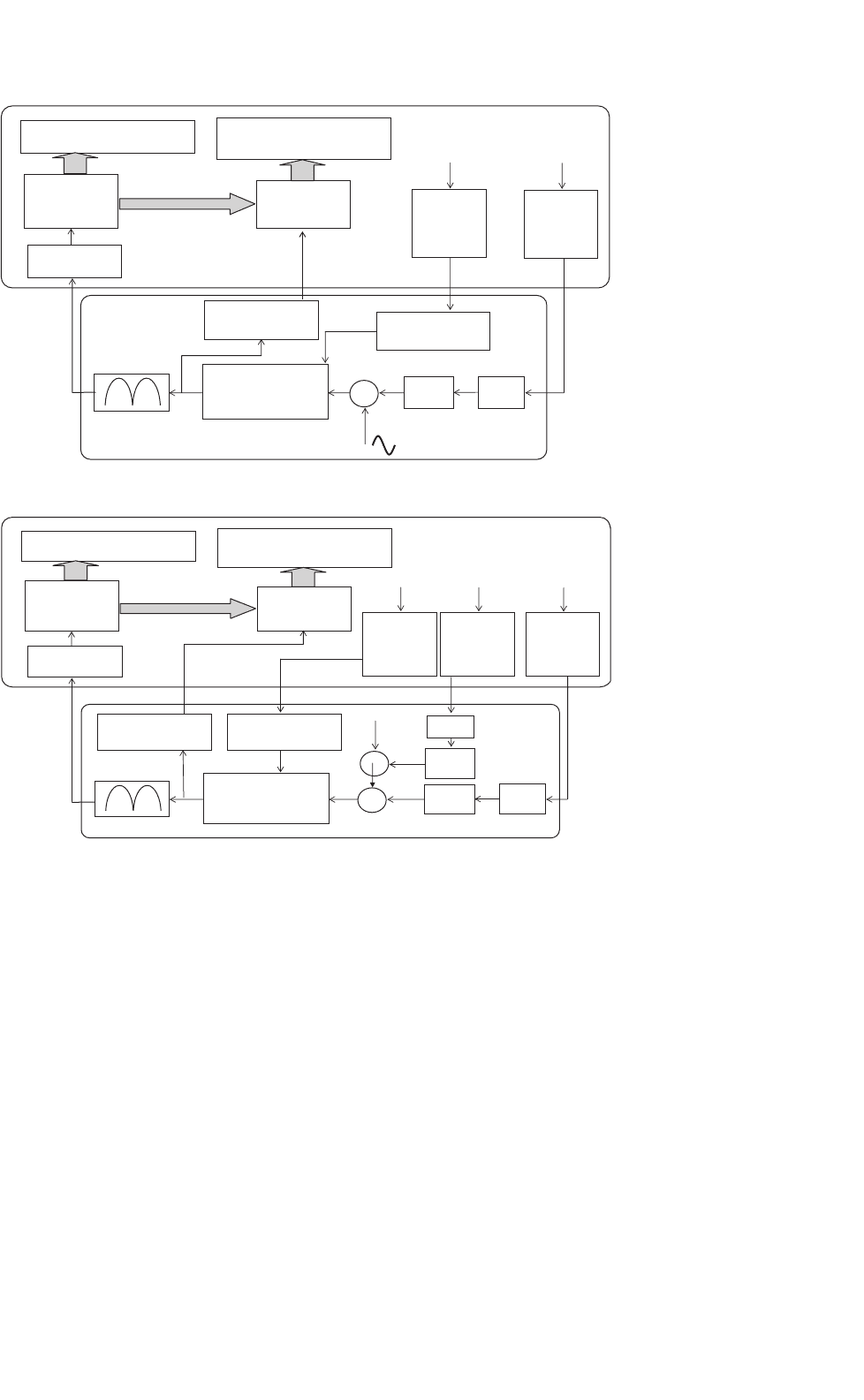
(c)
+
–
Filter
V
ref
G
c
= K
p
+ K
i
/s
Zero-crossing
detection
Compensator
Voltage
Sensor
Gain
Voltage
Sensor
Gain
UC3895
Phase-shift
Controller
DAC
HF Inverter Switches
Logical
Operations
Cycloconverter
Switches
ADC
V
Cf
Adaptive K
p
Selector
V
FC
DSP
On PCB
+
–
Filter
G
c
= K
p
+ K
i
/s
Zero-crossing
detection
Compensator
UC3895
Phase-shift
Controller
DAC
HF Inverter Switches
Logical
Operations
Cycloconverter
Switches
ADC
v
grid
ADC
P
o
x
/
Voltage
Sensor
Gain
Voltage
Sensor
Gain
v
FC
i
Lf
Adaptive K
p
Selector
Filter
(d)
Current
Sensor
Gain
FIGURE 28.11 continued
0.5 ×I
out
is positive and flows through the switches pair S
5
and S
5
, the output filter L
f 2
and C
f 2
, switches S
6
and S
6
, and
the transformer secondary.
Mode 2 (Fig. 28.12b): At the beginning of this interval the
gate voltage of the switch Q
1
undergoes a high-to-low tran-
sition. As a result, the output capacitance of Q
1
begins to
accumulate charge and at the same time the output capacitance
of switch Q
4
begins to discharge. Once the voltage across Q
4
goes to zero, it is can be turned on under ZVS. The transformer
primary currents I
p1
and I
p2
and the load current I
out
con-
tinue to flow in the same direction. This mode ends, when the
switch Q
1
is completely turned off and its output capacitance
is charged to V
DC
.
Mode 3 (Fig. 28.12c): This mode initiates when Q
1
turns
off. The transformer primary currents I
p1
and I
p2
are still
positive, and freewheels through Q
4
as shown in Fig. 28.12c.
Also the load current continues to flow in the same direction
as in Mode 2. Mode 3 ends at the commencement of turn
off Q
2
.
Mode 4 (Fig. 28.12d): At the beginning of this interval, the
gate voltage of Q
2
undergoes a high-to-low transition. As a
result of this, the output capacitance of Q
2
begins to accu-
mulate charge and at the same time, the output capacitance
of switch Q
3
begins to discharge as shown in the Fig. 28.12d.
The charging current of Q
2
and the discharging current of
Q
3
together add up to the primary current I
p1
and I
p2
.
728 S. K. Mazumder
Q
2
Q
4
V
DC
1:N
I
p1
+
V
p1
–
L
f1
C
1
C
f1
HF Inverter HF InverterAC/AC
Load
Q
3
Q
1
1:N
+
V
p2
–
L
f2
C
f2
S
1
S
2
S
3
S
4
S
5
S
6
S
7
S
8
Va
Va
Va
n
n
n
I
out
0.5I
out
0.5
I
p2
S
1
’
S
3
’
S
4
’
S
2
’
S
5
’
S
7
’
S
8
’
S
6
’
I
s1
+
I
s1–
I
s2+
I
s2–
+
V
out
–
Mode1
Mode2
Q
2
Q
4
V
DC
1:N
I
p1
+
V
p1
–
L
f1
C
1
C
f1
AC/AC
Load
Q
3
Q
1
1:N
+
V
p2
–
L
f2
C
f2
S
1
S
2
S
3
S
4
S
5
S
6
S
7
S
8
V
a
Va
V
a
n
n
n
I
out
0.5
0.5I
out
I
p2
S
1
’
S
3
’
S
4
’
S
2
’
S
5
’
S
7
’
S
8
’
S
6
’
I
s1+
I
s1–
I
s2+
I
s2–
+
V
out
–
(a)
(b)
I
out
I
out
Mode3
Q
2
Q
4
V
DC
1:N
I
p1
+
V
p1
–
L
f1
C
1
C
f1
HF Inverter AC/AC
Load
Q
3
Q
1
1:N
+
V
p2
–
L
f2
C
f2
S
1
S
2
S
3
S
4
S
5
S
6
S
7
S
8
V
a
V
a
V
a
n
n
n
I
out
0.5
0.5
I
p2
S
1
’
S
3
’
S
4
’
S
2
’
S
5
’
S
7
’
S
8
’
S
6
’
I
s1+
I
s1–
I
s2+
I
s2–
+
V
out
–
Mode4
Q
2
V
DC
C
1
Q
1
Q
3
1:N
I
p1
+
V
p1
–
L
f1
C
f1
HF Inverter AC/AC
Load
1:N
+
V
p2
–
L
f2
C
f2
S
1
S
2
S
3
S
4
S
5
S
6
S
7
S
8
V
a
V
a
V
a
n
n
n
I
out
0.5
0.5
I
p2
S
1
’
S
3
’
S
4
’
S
2
’
S
5
’
S
7
’
S
8
’
S
6
’
I
s1+
I
s1–
I
s2+
I
s2–
+
V
out
–
(c) (d)
I
out
I
out
I
out
I
out
Q
4
V
a
I
out
+
I
p1
C
1
Q
1
Q
2
Q
4
Q
3
C
f2
V
a
V
b
n
n
0.5
I
out
0.5I
out
I
p2
’’
S
8
S
6
S
8
S
6
S
5
S
4
S
7
S
1
S
3
S
1
S
3
S
4
S
2
S
2
S
5
S
7
Load
V
out
n
–
Mode5
V
DC
1:N
+
V
p1
–
C
f1
HF Inverter AC/AC
1:N
+
–
’’
’
’
’’
I
s1+
I
s1–
I
s2+
I
s2–
(e)
L
f1
L
f2
V
p2
Q1
Q2
Q4 Q1
Q3
V
p1
, V
p2
HF Inverter
Gating
Pulses
Mode 1
Mode2 & 3
Mode4 & 5
Mode 3
Mode 1
I
s1+
, I
s2+
I
p1
, I
p2
I
s1–
, I
s2–
S
3
, S
4
, S
7
, S
8
S
1
, S
2
, S
5
, S
6
P
V
, P
I
(f)
FIGURE 28.12 Modes of operation for 120 V ac for input voltage in the range of 42–60 V (N = 4.3): (a–e) topologies corresponding to the five
operating modes of the overall dc/ac converter for positive primary current and for power flow from the input to the load and (f) schematic
waveforms show the operating modes of the HF inverter when primary currents are positive. The modes of operation below 42 V (i.e. N = 6.5) remains
the same.
28 Fuel-cell Power Electronics for Distributed Generation 729
The transformer current makes a transition from positive to
negative. Once the voltage across Q
3
goes to zero, it is turned
on under ZVS. The load current flows in the same direction as
in Mode 3, but makes a rapid transition from the bidirectional
switches S
1
and S
1
and S
2
and S
2
to S
3
and S
3
and S
4
and S
4
and during this process I
out
/2 splits between the two legs of the
cycloconverter modules as shown in Fig. 28.12d. Mode 4 ends
when the switch Q
2
is completely turned off and its output
capacitance is charged to V
DC
. At this point, it is necessary to
note that since S
1
and S
2
are off simultaneously, each of them
support a voltage of V
DC
.
Mode 5 (Fig. 28.12e): This mode starts when Q
2
is com-
pletely turned off. The primary current I
p1
and I
p2
is negative,
while the load current is positive as shown in Fig. 28.12e.
C. Low-cost Fuel-cell Power Conditioner
Low cost power electronics system (PES) that converts a fuel
cell stack’s low voltage (typically 30–60 V) output into a com-
mercial ac output is critical for the success of fuel-cell energy
system, especially for the low power applications (≤3 kW).
According to [20], the cost of stationary residential PES should
be less than $40/kW for high volume of production. Many
types of configurations have been tried to achieve fuel-cell
power conversion at lower cost without compromising effi-
ciency [5, 7, 11–13, 19, 21–23]. Based on where the transformer
is inserted for isolating the fuel cell from the load, they can be
broadly categorized into two types of topologies.
The first type, usually called “dc/dc type converter,” uses
a dc/dc at front end to boost the low input voltage. The
transformer is inserted into the dc/dc stage which usually
is a push–pull or full-bridge converter. A diode rectifier is
required at the secondary to obtain a higher dc voltage. Fol-
lowing the dc/dc stage, a non-isolated dc/ac stage is used to get
low frequency ac. Since this type of topology has three power
conversion stages (dc-high frequency ac–dc-low frequency ac),
C
a
C
b
C
1
Q
a
L
a
L
b
Q
b
Q
c
L
c
C
c
Q
d
C
2
C
d
L
d
T1
T2
+
_
V
i
V
o
Module 1
Module 2
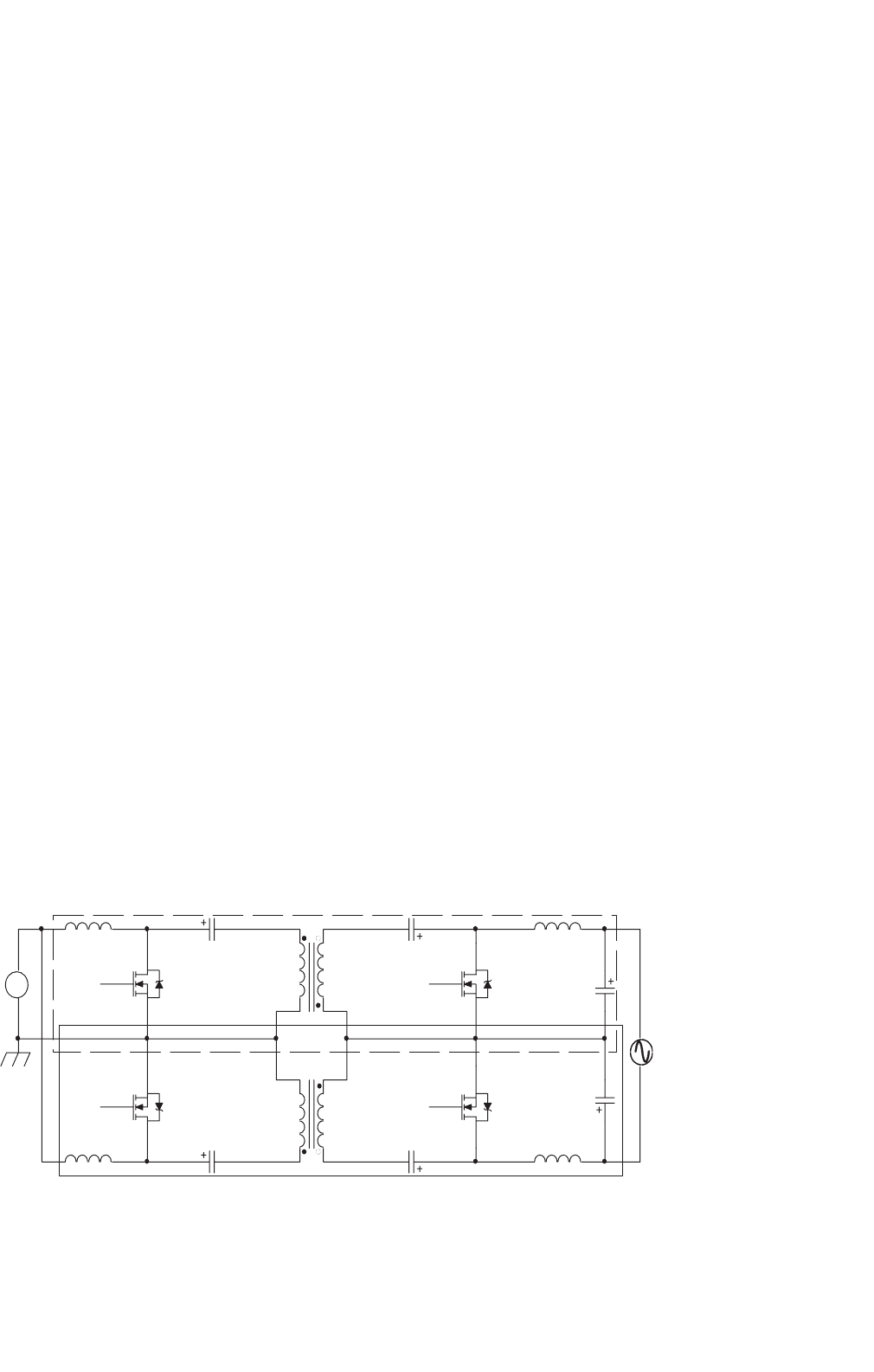
FIGURE 28.13 Schematic of the single-stage dc/ac differential isolated
ˆ
Cuk inverter.
it may not be the best choice from efficiency and cost point
of view because each stage has to have a very high efficiency
to make the overall efficiency high, and usually more than six
active components (switches and diodes) are required.
The second type of topology, referred as “cycloconverter
type converter,” reduce the system complexity by removing the
dc/dc stage. The galvanic isolation is achieved by embedding
the transformer into a dc/ac converter which usually composes
of a three-level or full-bridge inverter followed by a cyclo-
converter. Although it has lesser power conversion stage, the
number of active components may not necessary be less than
that of the first type mainly due to the bidirectional switches,
which are required for the cycloconverter.
A single-stage isolated dc/ac inverter, which was originally
proposed in [15] as “push–pull amplifier” achieves direct
dc/ac conversion by connecting load differentially across two
bidirectional dc/dc Cuk converters and modulating them sinu-
soidally with 180
◦
phase difference (Fig. 28.13). Since only four
main switches are used, it would potentially reduce system
complexity, costs, improve reliability, and increase efficiency.
Furthermore, the common source connection between two
devices both at primary and secondary sides (Q
a
and Q
c
and
Q
b
and Q
d
in Fig. 28.13) makes the gate drive circuit rela-
tively simple. In addition, the possibility of coupling inductors
or integrated magnetics [24] will further reduce the overall
volume and weight thereby achieving lesser material and space
usage. Therefore, it would be a better alternative for fuel-cell
application and will eventually lead to a very low cost, high
density power conversion system.
Another advantage of this inverter is the reduction of turns
ratio of the step-up transformer, which is usually required
to achieve rated ac from low fuel-cell stacks dc voltage. The
inherent voltage boosting capability of the dc/ac Cuk inverter
can reduce the transformer turns ratio requirement by at least
half. Low transformer turns ratio yields less leakage inductance

730 S. K. Mazumder
and secondary winding resistance, which reduces the loss of
duty cycle and secondary copper losses, respectively.
Although the non-isolated dc/ac inverter has already been
proposed [15], analysis of the isolated version has not appeared
in any literature, nor have the issues involved in the design
towards higher power rating (>1 kW) for fuel-cell application.
Reference [25] presents the analysis and design of a 1 kW fuel
cell PES using the isolated differential Cuk inverter.
The output of the proposed dc/ac inverter is the difference
between two “sine-wave modulated PWM controlled” isolated
Cuk inverter (module 1 and module 2), with their primary
sides connected in parallel. The two diagonal switches of two
modules are triggered by a same signal (Q
a
= Q
d
,Q
b
= Q
c
),
while the two switches in each module have complementary
gate signals (Q
a
= /Q
b
,Q
c
= /Q
d
). As we know, the output
voltage of an isolated Cuk inverter can be expressed as
V
o
= V
i
·
D
N (1 − D)
(28.11)
where D is the duty ratio, N is the transformer turns ratio,
V
i
is the input voltage. Since duty ratios for module 1 and
module 2 are complementary, the output difference between
two modules is:
V
o
= V cl −V c2 =V
i
·
D
N · (1 − D)
−
1 −D
N ·D
(28.12)
The curves corresponding to the terms in Eq. (28.12) with
respect to the duty ratio D (assuming N = 1) are plotted in
Fig. 28.14. The figure shows that although the gain-duty ratio
0.3 0.35 0.4 0.45 0.5 0.55 0.6 0.65 0.7
–2
–1.5
–1
–0.5
0
0.5
1
1.5
2
D
V
out
/V
in
FIGURE 28.14 Voltage gain vs D for module 1 (top), module 2 (bottom), and their difference (middle).
curves of modules 1 and 2 are not linear, their difference is
almost linear. Therefore, if a sine-wave modulated duty ratio
D is used as a control signal for inverter in Fig. 28.13, its output
voltage will be a sine wave with small distortion [15].
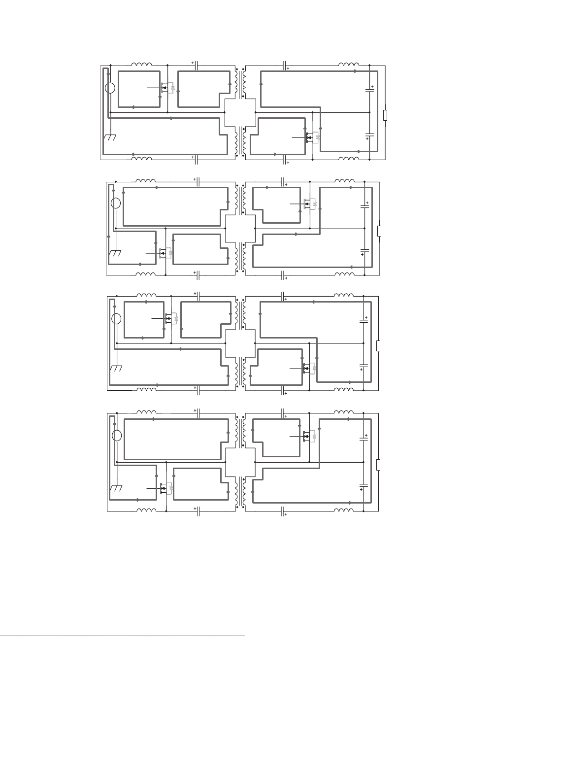
In order to understand how the current flows and energy
transfers during the switching and to help select the device
rating, four different modes of the inverter are analyzed and
shown in Fig. 28.15. Figures 28.15a, b show the direction
of the current when the load current flows from top to the
bottom.
Mode 1: Figure 28.15a shows the current flow for the case
when switch Q
a
,Q
d
are ON and Q
b
,Q
c
are OFF. During
this time, the current flowing through the input inductor L
a
increases and the inductor stores energy. At the same time, the
capacitor C
a
discharges through Q
a
, and thus, there is transfer
of energy from primary side to the secondary side through the
transformer T
1
. The capacitor C
b
is discharged to the circuit
formed by L
b
, C
1
, and the load R. Meanwhile, the inductor
L
d
stores energy and its current increases. The capacitor C
d
discharges through Q
d
. The power flows in opposite direc-
tion in the module 2 from secondary to the primary side. The
capacitor C
c
is also discharged to provide the power.
Mode 2: When Q
a
,Q
d
are turned off, and Q
b
,Q
c
are
ON (Fig. 28.15b) C
a
, C
d
and C
b
, C
c
are charged using the
energy, which was stored in the inductors L
a
and L
d
while
Q
a
,Q
d
were on. During this time, L
b
and L
c
will release their
energy.
Figures 28.15c, d show the current direction when the
load current flows in the opposite direction. The description
for these two modes is omitted due to the similarity with
Figs. 28.15a, b.
28 Fuel-cell Power Electronics for Distributed Generation 731
C
a
C
b
C
1
Q
a
L
a
L
b
L
c
C
c
C
2
C
d
L
d
T
1
T
2
+
-
V
i
V
o
R
Q
d
C
a
C
b
C
1
Q
b
L
a
L
b
L
c
C
c
C
2
C
d
L
d
T
1
T
2
V
i
R
Q
c
+
-
V
o
C
a
C
b
C
1
Q
a
L
a
L
b
L
c
C
c
C
2
C
d
L
d
T
1
T
2
+
-
V
i
V
o
R
Q
d
C
a
C
b
C
1
Q
b
L
a
L
b
L
c
C
c
C
2
C
d
L
d
T
1
T
2
V
i
R
Q
c
+
-
V
o
(a)
(b)
(c)
(d)
FIGURE 28.15 (a) and (b) Direction of the current flow in two modes of operation for positive load current: (a) Mode 1, when Q
a
,Q
d
are ON,
Q
b
,Q
c
are OFF and (b) Mode 2 when Q
a
,Q
d
are OFF Q
b
,Q
c
are ON. Figures 28.15c, d are the corresponding current flow when load current flows
in the opposite direction.
28.4 Towards Power-electronic
Topologies for High Power
Fuel-cell Based DG
In addition to residential use, fuel cells are being increas-
ingly considered for high-power (MW-power) applications.
In that context, currently, Department of Energy’s (DOEs)
focus is on reactive-power and harmonic compensations
and high-temperature coal-power applications. Due to the
practical manufacture limitation and reliability concern, the
maximal output voltage and output power of one fuel-cell
stack cannot be too high. To provide the desired amount of
voltage and/or power, multiple fuel-cell stacks are required
to form a fuel-cell module. These modules along with their
power conditioning system can be connected in several dif-
ferent configurations, which will be presented in this section.

732 S. K. Mazumder
Fuel Cell
Module
Fuel Cell
Module
Fuel Cell
Module
Fuel Cell
Module
Fuel Cell
Module
Three
Phase
Power
Converter
Three
Phase
Loads
FIGURE 28.16 A general diagram of multiple fuel-cell modules con-
nected in series to generate dc bus followed by a three-phase inverter.
Copyright © IEEE, 2003, Ozpineci etc. [26].
The advantages and disadvantages of each approach are also
summarized.
One of the most common configurations of fuel-cell mod-
ules and PCS for high power application is to connect multiple
fuel-cell modules directly in series and apply the obtained dc
bus to a three-phase dc/ac inverter, as shown in Fig. 28.16. For
each module, fuel-cell stacks can also be connected in parallel
to provide the required power, if necessary.
For the inverter, recently, multilevel power conversion
has received increasing attention for medium-voltage and
high power applications. Among the multilevel topologies,
diode-clamped inverter, capacitor-clamped (flying capacitor)
inverter, and cascaded multi-cell inverter with separate dc
sources are the three basic architectures. Other emerging novel
topologies include asymmetric hybrid cells and soft-switched
multilevel inverters [27].
Multilevel inverters include an array of power semiconduc-
tor devices and voltage sources. They generate output voltage
with stepped waveforms. Figure 28.17 shows a schematic dia-
gram of one phase leg multilevel converter with different
number of levels. Note the actual power devices are replaced
by ideal switches with several positions. Figure 28.17a is a
two-level inverter since the output voltage V
a
has only two
possible values, while Fig. 28.17b is a three-level inverter
since its output can have three different values. If m is the
number of possible output voltage levels, it is called m-level
inverter (Fig. 28.17c). By increasing the number of levels,
the output voltage waveforms will have more steps and thus
have a reduced harmonic distortion. However, a high number
(
a
)(
b
)(
c
)
V
c
V
c
V
c
V
c
V
c
V
c
V
a
V
a
V
a
ooo
a
a
a
+
+
+
+
+
+
FIGURE 28.17 One phase multilevel diagram: (a) two levels; (b) three
levels; and (c) n-levels. Copyright © IEEE, 2002, Rodriguez etc. [27].
of levels will increase the complexity and introduce voltage
imbalance problems.
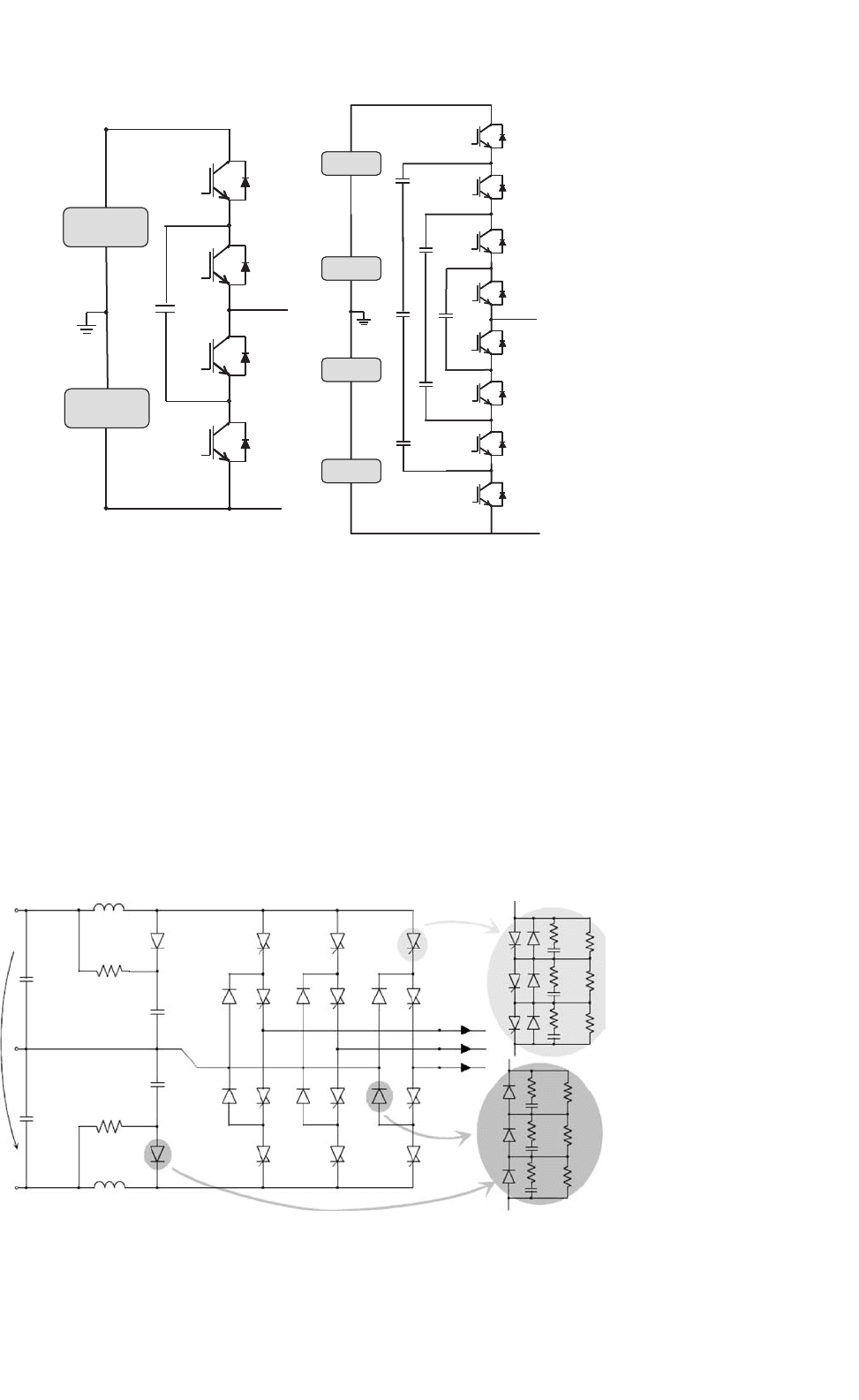
Figure 28.18 show the diagrams of one phase leg fuel-cell
power conditioner for high power applications using diode-
clamped multilevel inverter. Its operational principle was
explained in [27]. The number of switches equals 2 ×(m −1).
The key components that make the circuit different are clamp
diodes, which clamp the switch voltage to the corresponding
level of the dc bus voltage. Assuming all the clamp diodes are
the same, the number of diodes required for each leg will be
(m −1) ×(m −2). This represents a quadratic increase in m
(number of levels). Another problem caused by diode clamp-
ing is if the inverter operates under high frequency, the diode
reverse recovery will become a major design challenges.
n
a
o
a
o
n
(a) (b)
Fuel Cell
Module
Fuel Cell
Module
Fuel Cell
Module
Fuel Cell
Module
Fuel Cell
Module
Fuel Cell
Module
FIGURE 28.18 Schematics of one phase leg fuel-cell power conditioner
for high power applications using diode-clamped multilevel inverter: (a)
three-level and (b) five-level inverter. Copyright © IEEE 2002, Rodriguez
etc. [27] and 2003, Ozpineci etc. [26].
28 Fuel-cell Power Electronics for Distributed Generation 733
n
a
o
Fuel Cell
Module
Fuel Cell
Module
o
a
n
(a) (b)
Fuel Cell
Module
Fuel Cell
Module
Fuel Cell
Module
Fuel Cell
Module
FIGURE 28.19 Schematics of one phase leg fuel-cell PCS for high power applications using capacitor-clamped multilevel inverter: (a) three-level
and (b) five-level inverter. Copyright © IEEE, 2002, Rodriguez etc. [27].
Figure 28.19 show diagrams of one phase leg multilevel
capacitor-clamped inverter. The operational principle is sim-
ilar to diode-clamped type multilevel except the clamping of
device voltages is achieved by the flying capacitors [27]. Similar
to diode-clamping, capacitor clamping requires a large num-
ber of bulk capacitors to clamp the voltage. For a m-level
inverter, a total of (m − 1) × (m − 2)/2 clamping capacitors
are needed per phase leg.
Figure 28.20 shows a 24 MVA NPC inverter using inte-
grated gate commutated thyristor (IGCT) series connection
V
dc
L
S1
L
S2
R
S1
R
S2
D
CI
D
C2
D
16
D
15
D
25
D
26
D
36
D
35
T
11
T
21
T
22
T
23
T
24
T
34
T
33
T
32
R
snub
R
p
R
p
R
p
R
p
R
p
R
p
C
snub
R
snub
C
snub
R
snub
C
snub
R
snub
C
snub
R
snub
C
snub
R
snub
C
snub
T
31
T
12
T
13
T
14
C
C1
C
C2
v
1.3
i
ph (1.3)
FIGURE 28.20 A 24 MVA inverter using IGCT series connection for medium-voltage applications. Copyright © IEEE, 2001 Nagel etc. [28].
for medium-voltage applications [28]. Topology used here is
a diode clamped three-level inverter with series connection
of semiconductors. The overall input dc bus voltage V
dc
is
14.4 kV. To sustain this voltage, each switch is composed of
three 4.5 kV IGCTs and each diode is made up of three 4.5 kV
diodes. The RC snubbers are also used for the purpose of
voltage balancing.
As compared to the other configurations, the series con-
nection of fuel-cell modules followed by an inverter has
less complexity and less number of semiconductor devices.