Power electronic handbook
Подождите немного. Документ загружается.

704 C. V. Nayar et al.
not desired that the grid supply this reactive power, these
generators are usually equipped with capacitors. A gear box
forms an essential component of the wind turbine genera-
tor (WTG) using induction generators. This results in the
following limitations:
• Frequent maintenance.
• Additional cost.
• Additional losses.
With the emergence of large wind power generation,
increased attention is being directed towards wound rotor
induction generators (WRIG) controlled from the rotor side
for variable speed constant frequency (VSCF) applications. A
wound rotor induction generator has a rotor containing a
3-phase winding. These windings are made accessible to the
outside via slip rings. The main advantages of a wound rotor
induction generator for VSCF applications are:
• Easier generator torque control using rotor current
control.
• Smaller generator capacity as the generated power can be
accessed from the stator as well as from the rotor. Usually
the rotor power is proportional to the slip speed (shaft
speed–synchronous speed). Consequently smaller rotor
power converters are required. The frequency converter
in the rotor (inverter) directly controls the current in the
rotor winding, which enables the control of the whole
generator output. The power electronic converters gen-
erally used are rated at 20–30% of the nominal generator
power.
•
Fewer harmonics exist because control is in the rotor
while the stator is directly connected to the grid.
If the rotor is short-circuited (making it the equivalent of
a cage rotor induction machine), the speed is primarily deter-
mined by the supply frequency and the nominal slip is within
5%. The mechanical power input (P
TURBINE
) is converted into
stator electrical power output (P
STATOR
) and is fed to the AC
supply. The rotor power loss, being proportional to the slip
speed, is commonly referred to as the slip power (P
ROTOR
).
(a) (b)
P
S TATOR
P
STATOR
P
TURBINE
P
TURBINE
P
ROTOR
P
ROTOR
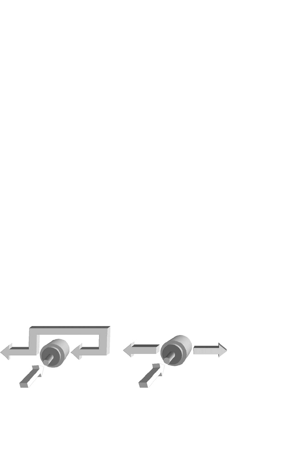
FIGURE 27.57 Doubly-fed induction generator power flow in generating mode: (a) sub-synchronous and (b) super-synchronous.
The possibility of accessing the rotor in a doubly-fed induction
generator makes a number of configurations possible. These
include slip power recovery using a cycloconverter, which
converts the ac voltage of one frequency to another with-
out an intermediate DC link [56–58], or back-to-back inverter
configurations [59, 60].
Using voltage-source inverters (VSIs) in the rotor circuit,
the rotor currents can be controlled at the desired phase,
frequency, and magnitude. This enables reversible flow of
active power in the rotor and the system can operate in sub-
synchronous and super-synchronous speeds, both in motoring
and generating modes. The DC link capacitor acts as a source
of reactive power and it is possible to supply the magnetiz-
ing current, partially or fully, from the rotor side. Therefore,
the stator side power factor can also be controlled. Using vec-
tor control techniques, the active and reactive powers can be
controlled independently and hence fast dynamic performance
can also be achieved.
The converter used at the grid interface is termed as the
line-side converter or the front end converter (FEC). Unlike
the rotor side converter, this operates at the grid frequency.
Flow of active and reactive powers is controlled by adjusting
the phase and amplitude of the inverter terminal voltage with
respect to the grid voltage. Active power can flow either to the
grid or to the rotor circuit depending on the mode of oper-
ation. By controlling the flow of active power, the DC bus
voltage is regulated within a small band. Control of reactive
power enables unity power factor operation at the grid inter-
face. In fact, the FEC can be operated at a leading power factor,
if it is so desired. It should be noted that, since the slip range is
limited, the DC bus voltage is less in this case when compared
to the stator side control. A transformer is therefore necessary
to match the voltage levels between the grid and the DC side of
the FEC. With a PWM converter in the rotor circuit, the rotor
currents can be controlled at the desired phase, frequency,
and magnitude. This enables reversible flow of active power in
the rotor and the system can operate in sub-synchronous and
super-synchronous speeds, both in motoring and generating
modes (Fig. 27.57).
27 Power Electronics for Renewable Energy Sources 705
27.3.2 Types of Wind Power Systems
Wind power systems can be classified as:
• Stand-alone.
•
Hybrid.
• Grid-connected.
27.3.3 Stand-alone Wind Power Systems
Stand-alone wind power systems are being used for the
following purposes in remote area power systems:
• Battery charging.
• Household power supply.
27.3.3.1 Battery Charging with Stand-alone Wind
Energy System
The basic elements of a stand-alone wind energy conversion
system are:
• Wind generator.
• Tower.
• Charge control system.
• Battery storage.
•
Distribution network.
In remote area power supply, an inverter and a diesel gen-
erator are more reliable and sophisticated systems. Most small
isolated wind energy systems use batteries as a storage device to
level out the mismatch between the availability of the wind and
the load requirement. Batteries are a major cost component in
an isolated power system.
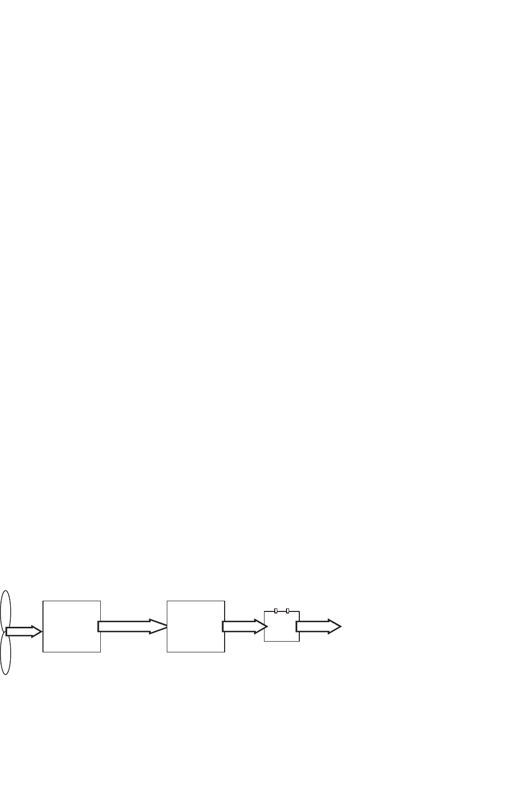
27.3.3.2 Wind Turbine Charge Controller
The basic block diagram of a stand-alone wind generator and
battery charging system is shown in Fig. 27.58.
The function of charge controller is to feed the power from
the wind generator to the battery bank in a controlled manner.
In the commonly used permanent magnet generators, this is
usually done by using the controlled rectifiers [61]. The con-
troller should be designed to limit the maximum current into
Generator
Charge
controller
Battery
Wind
turbine
To
DC
load
Permanent Magnet
or Capacitor Excited
FIGURE 27.58 Block diagram for a stand-alone wind generator and battery charging system.
the battery, reduce charging current for high battery SOC, and
maintain a trickle charge during full SOC periods.
27.3.4 Wind–diesel Hybrid Systems
The details of hybrid systems are already covered in
Section 27.2.4. Diesel systems without batteries in remote area
are characterized by poor efficiency, high maintenance, and
fuel costs. The diesel generators must be operated above a cer-
tain minimum load level to reduce cylinder wear and tear due
to incomplete combustion. It is a common practice to install
dump loads to dissipate extra energy. More efficient systems
can be devised by combining the diesel generator with a battery
inverter subsystem and incorporating RES, such as wind/solar
where appropriate. An integrated hybrid energy system incor-
porating a diesel generator, wind generator, battery or flywheel
storage, and inverter will be cost effective at many sites with
an average daily energy demand exceeding 25 kWh [62]. These
hybrid energy systems can serve as a mini grid as a part
of distributed generation rather than extending the grid to
the remote rural areas. The heart of the hybrid system is a
high quality sine-wave inverter, which can also be operated
in reverse as battery charger. The system can cope with loads
ranging from zero (inverter only operation) to approximately
three times greater capacity (inverter and diesel operating in
parallel).
Decentralized form of generation can be beneficial in remote
area power supply. Due to high cost of PV systems, prob-
lems associated with storing electricity over longer periods
(like maintenance difficulties and costs), wind turbines can
be a viable alternative in hybrid systems. Systems with battery
storage although provide better reliability. Wind power pen-
etration can be high enough to make a significant impact on
the operation of diesel generators.
High wind penetration also poses significant technical prob-
lems for the system designer in terms of control and transient
stability [30]. In earlier stages, wind diesel systems were
installed without assessing the system behavior due to lack
of design tools/software. With the continual research in this
area, there are now software available to assist in this process.
Wind diesel technology has now matured due to research and
development in this area. Now there is a need to utilize this
706 C. V. Nayar et al.
knowledge into cost effective and reliable hybrid systems [63].
In Western Australia, dynamic modeling of wind diesel hybrid
system has been developed in Curtin/MUERI, supported by
the Australian Cooperative Research Centre for Renewable
Energy (ACRE) program 5.21.
27.3.5 Grid-connected Wind Energy Systems
Small scale wind turbines, connected to the grid (weak or
strong grid), have been discussed here. Wind diesel systems
have been getting attention in many remote parts of the world
lately. Remote area power supplies are characterized by low
inertia, low damping, and poor reactive power support. Such
weak power systems are more susceptible to sudden change
in network operating conditions [64]. In this weak grid sit-
uation, the significant power fluctuations in the grid would
lead to reduced quality of supply to users. This may manifest
itself as voltage and frequency variations or spikes in the power
supply. These weak grid systems need appropriate storage and
control systems to smooth out these fluctuations without sac-
rificing the peak power tracking capability. These systems can
have two storage elements. The first is the inertia of the rotat-
ing mechanical parts, which includes the blades, gearbox, and
the rotor of the generators. Instead of wind speed fluctuation
causing large and immediate change in the electrical output
of the generator as in a fixed speed machine, the fluctuation
will cause a change in shaft speed and not create a signifi-
cant change in generator output. The second energy storage
element is the small battery storage between the DC–DC con-
verter and the inverter. The energy in a gust could be stored
temporarily in the battery bank and released during a lull in
the wind speed, thus reducing the size of fluctuations.
In larger scale wind turbines, the addition of inverter con-
trol further reduces fluctuation and increases the total output
power. Thus the total output of the wind energy system can
be stabilized or smoothed to track the average wind speed and
can omit certain gusts. The system controller should track the
peak power to maximize the output of the wind energy system.
It should monitor the stator output and adjust the inverter
to smooth the total output. The amount of smoothing would
depend on SOC of the battery. The nominal total output would
be adjusted to keep the battery bank SOC at a reasonable level.
In this way, the total wind energy system will track the long-
term variations in the wind speed without having fluctuations
caused by the wind. The storage capacity of the battery bank
need only be several minutes to smooth out the gusts in the
wind, which can be easily handled by the weak grid. In the
cases, where the weak grid is powered by diesel generators,
the conventional wind turbine can cause the diesel engines to
operate at low capacity. In case of strong wind application, the
fluctuations in the output of the wind energy generator system
can be readily absorbed by the grid. The main aim here is to
extract the maximum energy from the wind. The basic block
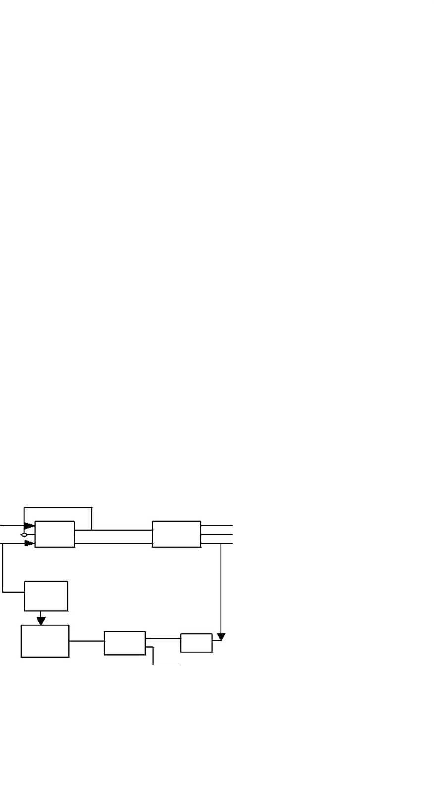
layout of such a system [65] is shown in the Fig. 27.59.
Stator
Rotor
DC to DC
Converter
DC to AC
Inverter
System
Controller
Battery
Wind
speed
Grid
FIGURE 27.59 System block diagram of grid-connected wind energy
system.
The function of the DC–DC converter will be to adjust
the torque on the machine and hence ensure by measure-
ment of wind speed and shaft speed that the turbine blades
are operating so as to extract optimum power. The purpose
of the inverter is to feed the energy gathered by the rotor
and DC–DC converter, in the process of peak power tracking,
to the grid system. The interaction between the two sections
would be tightly controlled so as to minimize or eliminate the
need for a battery bank. The control must be fast enough so
that the inverter output power set point matches the output of
the DC–DC converter. For a wound rotor induction machine
operating over a two to one speed range, the maximum power
extracted from the rotor is equal to the power rating of the sta-
tor. Thus the rating of the generator from a traditional point
of view is only half that of the wind turbine [65]. Since half
the power comes from the stator and half from the rotor,
the power electronics of the DC–DC converter and inverter
need to handle only half the total wind turbine output and no
battery would be required.
Power electronic technology also plays an important role
in both system configurations and in control of offshore
wind farms [66]. Wind farms connect in various configura-
tions and control methods using different generator types and
compensation arrangements. For instance, wind farms can be
connected to the AC local network with centralized compen-
sation or with a HVDC transmission system, and DC local
network. Decentralized control with a DC transmission system
has also been used [67].
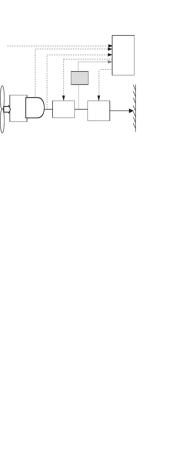
27.3.5.1 Soft Starters for Induction Generators
When an induction generator is connected to a load, a large
inrush current flows. This is something similar to the direct
online starting problem of induction machines. It has been
observed that the initial time constants of the induction
27 Power Electronics for Renewable Energy Sources 707
Wind turbine
+
Induction generator
Power distribution
system
FIGURE 27.60 Soft starting for wind turbine coupled with induction
generator.
machines are higher when it tries to stabilize initially at the
normal operating conditions. There is a need to use some
type of soft starting equipment to start the large induction
generators. A simple scheme to achieve this is shown in the
Fig. 27.60.
Two thyristors are connected in each phase, back-to-back.
Initially, when the induction generator is connected, the thyris-
tors are used to control the voltage applied to the stator and
to limit the large inrush current. As soon as the generator is
fully connected, the bypass switch is used to bypass the soft
starter unit.
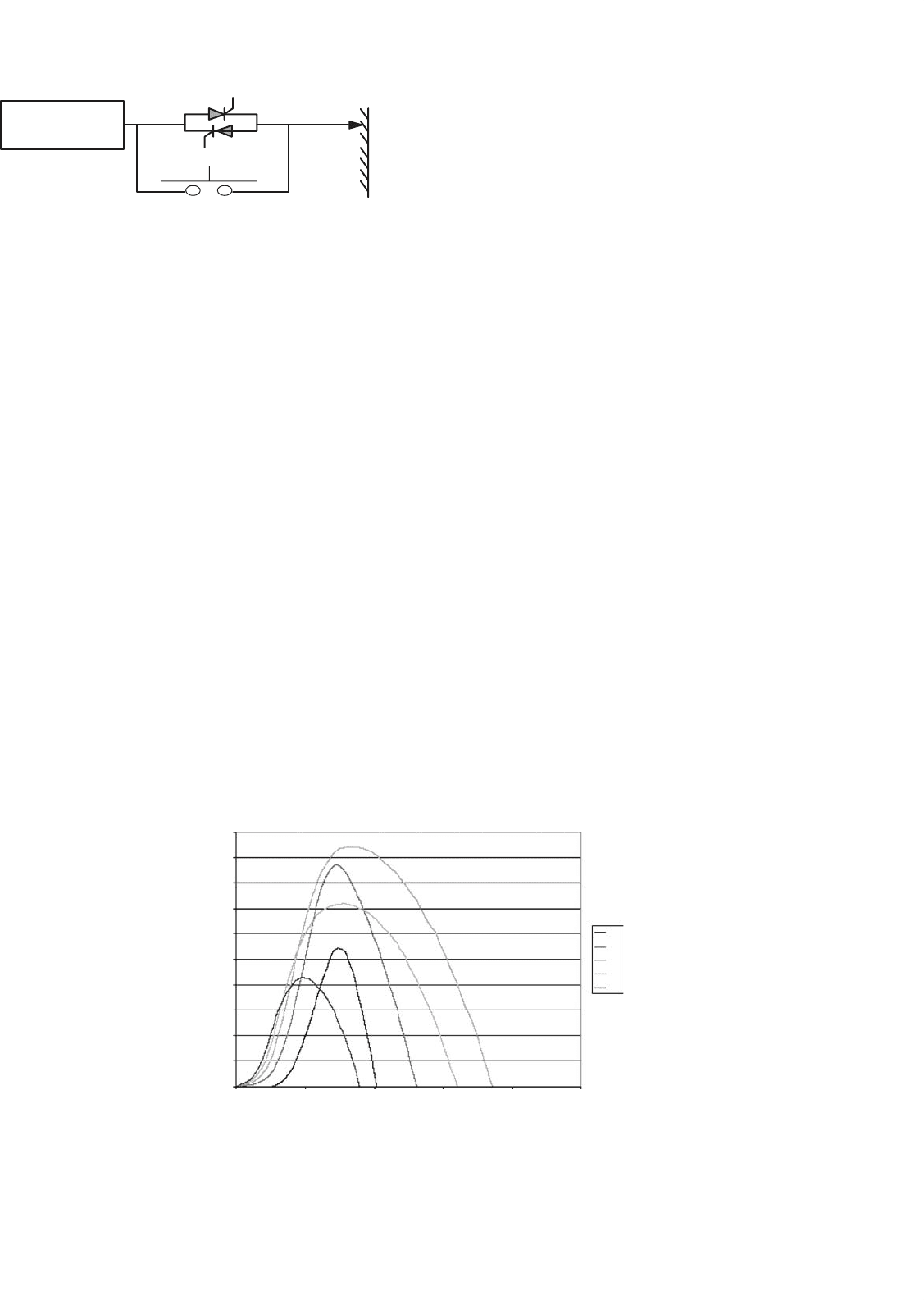
27.3.6 Control of Wind Turbines
Theory indicates that operation of a wind turbine at fixed
tip speed ratio (C
pmax
) ensures enhanced energy capture [50].
The wind energy systems must be designed so that above the
rated wind speed, the control system limit the turbine output.
In normal operation, medium to large-scale wind turbines are
connected to a large grid. Various wind turbine control policies
Curve index: pitch angle
0.5
0.45
0.4
0.35
0.3
0.25
C
p
0.2
0.15
0.1
0.05
0
0 5 10 15
lambda (tip speed ratio)
20 25
−10
−5
0
5
10
FIGURE 27.61 C
p
/λ curves for different pitch settings.
have been studied around the world. Grid-connected wind
turbines generators can be classified as:
• Fixed speed wind turbines.
• Variable speed wind turbines.
27.3.6.1 Fixed Speed Wind Turbines
In case of a fixed speed wind turbine, synchronous or squirrel-
cage induction generators are employed and is characterized
by the stiff power train dynamics. The rotational speed of the
wind turbine generator in this case is fixed by the grid fre-
quency. The generator is locked to the grid, thereby permitting
only small deviations of the rotor shaft speed from the nominal
value. The speed is very responsive to wind speed fluctuations.
The normal method to smooth the surges caused by the wind
is to change the turbine aerodynamic characteristics, either
passively by stall regulation or actively by blade pitch regu-
lation. The wind turbines often subjected to very low (below
cut in speed) or high wind speed (above rated value). Some-
times they generate below rated power. No pitch regulation is
applied when the wind turbine is operating below rated speed,
but pitch control is required when the machine is operating
above rated wind speed to minimize the stress. Figure 27.61
shows the effect of blade pitch angle on the torque speed curve
at a given wind speed.
Blade pitch control is a very effective way of controlling
wind turbine speed at high wind speeds, hence limiting the
power and torque output of the wind machine. An alterna-
tive but cruder control technique is based on airfoil stall [50].
A synchronous link maintaining fixed turbine speed in com-
bination with an appropriate airfoil can be designed so that,
at higher than rated wind speeds the torque reduces due to
708 C. V. Nayar et al.
airfoil stall. This method does not require external interven-
tion or complicated hardware, but it captures less energy and
has greater blade fatigue.
The aims of variable pitch control of medium- and large-
scale wind turbines were to help in start-up and shutdown
operation, to protect against overspeed and to limit the load
on the wind turbine [68]. The turbine is normally operated
between a lower and an upper limit of wind speed (typically
4.5–26 m/s). When the wind speed is too low or too high,
the wind turbine is stopped to reduce wear and damage. The
wind turbine must be capable of being started and run up
to speed in a safe and controlled manner. The aerodynamic
characteristics of some turbines are such that they are not
self starting. The required starting torque may be provided by
motoring or changing the pitch angle of the blade. In case of
grid-connected wind turbine system, the rotational speed of
the generator is locked to the frequency of the grid. When
the generator is directly run by the rotor, the grid acts like an
infinite load. When the grid fails, the load rapidly decreases to
zero resulting in the turbine rotor to accelerate quickly. Over-
speed protection must be provided by rapid braking of the
turbine. A simple mechanism of one of blade pitch control
techniques is shown in Fig. 27.62.
In this system, the permanent magnet synchronous gen-
erator (PMSG) has been used without any gearbox. Direct
connection of generator to the wind turbine requires the
generator to have a large number of poles. Both induction
generators and wound filed synchronous generators of high
pole number require a large diameter for efficient operation.
Permanent magnet synchronous generators allow a small pole
pitch to be used [69]. The power output, P
mech
, of any tur-
bine depends mainly upon the wind speed, which dictates the
rotational speed of the wind turbine rotor. Depending upon
the wind speed and rotational speed of turbine, tip speed ratio
rotor speed
Wind speed
Wind
Turbine
Generator
Measurement
filter
Voltage
Current
Torque
P
mech
T
mech
T
actual
T
desired
Blade
pitch
angle
Pitch
Actuator
Pitch
Controller
Pitch
demand
+
−
FIGURE 27.62 Pitch control block diagram of a PMSG.
λ is determined. Based on computed λ, the power coefficient
C
p
is inferred. In the control strategy above, the torque out-
put, T
actual
, of the generator is monitored for a given wind
speed and compared with the desired torque, T
actual
, depend-
ing upon the load requirement. The generator output torque
is passed through the measurement filter. The pitch controller
then infers the modified pitch angle based on the torque error.
This modified pitch angle demand and computed λ decides
the new C
p
resulting in the modified wind generator power
and torque output. The controller will keep adjusting the
blade pitch angle till the desired power and torque output
are achieved.
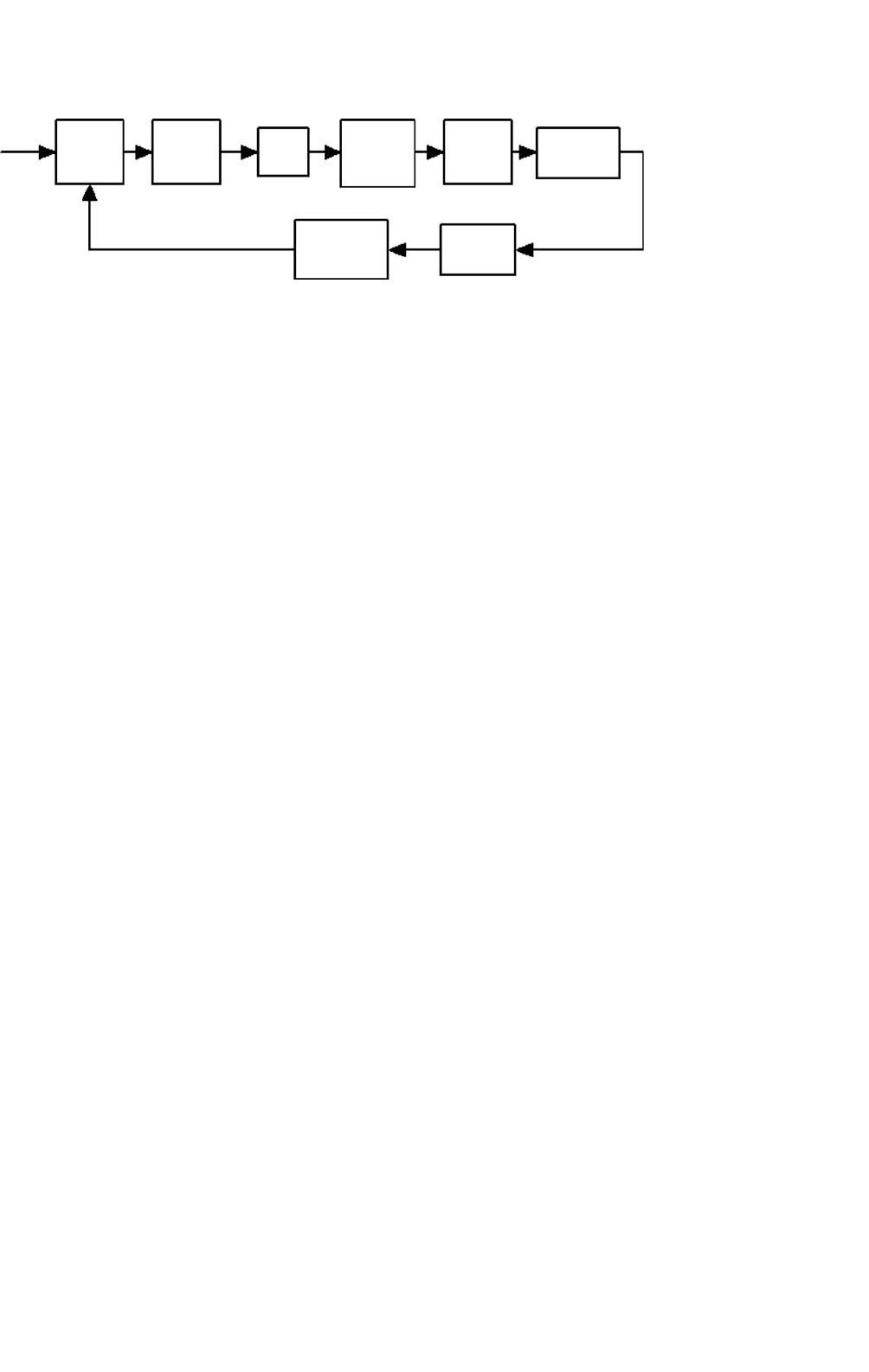
Some of the wind turbine generator includes the gearbox
for interfacing the turbine rotor and the generator. The gen-
eral drive train model [68] for such a system is shown in
Fig. 27.63. This system also contains the blade pitch angle
control provision.
The drive train converts the input aerodynamic torque on
the rotor into the torque on the low-speed shaft. This torque
on the low-speed shaft is converted to high-speed shaft torque
using the gearbox and fluid coupling. The speed of the wind
turbine here is low and the gear box is required to increase the
speed so as to drive the generator at rated rpm e.g. 1500 rpm.
The fluid coupling works as a velocity-in-torque-out device
and transfer the torque [68]. The actuator regulates the tip
angle based on the control system applied. The control system
here is based on a pitch regulation scheme where the blade
pitch angle is adjusted to obtain the desired output power.
27.3.6.2 Variable Speed Wind Turbines
The variable speed constant frequency turbine drive trains
are not directly coupled to the grid. The power-conditioning
device is used to interface the wind generator to the grid.
27 Power Electronics for Renewable Energy Sources 709
Wind
speed
Look
up table
blade
tip angle
Low
speed
shaft
Gear
box
Fluid
coupling
High
speed
shaft
Generator
Control
Pitch
Actuator
FIGURE 27.63 Block diagram of drive train model.
The output of the wind generator can be variable voltage and
variable frequency, which is not suitable for grid integration
and appropriate interfacing is required. The wind turbine rotor
in this case is permitted to rotate at any wind speed by power
generating unit.
A number of schemes have been proposed in the past which
allow wind turbines to operate with variable rotor speed while
feeding the power to a constant frequency grid. Some of the
benefits that have been claimed for variable speed constant
frequency wind turbine configuration is as follow [65]:
• The variable speed operation results in increased energy
capture by maintaining the blade tip speed to wind speed
ratio near the optimum value.
• By allowing the wind turbine generator to run at vari-
able speed, the torque can be fixed, but the shaft power
allowed to increase. This means that the rated power of
the machine can be increased with no structural changes.
• A variable speed turbine is capable of absorbing energy
in wind gusts as it speeds up and gives back this energy
to the system as it slows down. This reduces turbulence
induced stresses and allows capture of a large percentage
of the turbulent energy in the wind.
• More efficient operation can be achieved by avoiding
aerodynamic stall over most of operating range.
• Better grid quality due to support of grid voltage.
Progress in the power electronics conversion system has
given a major boost to implementing the concept of vari-
able speed operation. The research studies have shown that
the most significant potential advancement for wind turbine
technology was in the area of power electronic controlled vari-
able speed operation. There is much research underway in the
United States and Europe on developing variable speed wind
turbine as cost effective as possible. In United States, the NASA
MOD-0 and MOD-5B were operated as variable speed wind
turbines [65]. Companies in United States and Enercon (Ger-
many) made machines incorporate a variable speed feature.
Enercon variable speed wind machine is already in operation
in Denham, Western Australia.
The ability to operate at varying rotor speed, effectively
adds compliance to the power train dynamics of the wind
turbine. Although many approaches have been suggested for
variable speed wind turbines, they can be grouped into two
main classes: (a) discretely variable speed and (b) continuously
variable speed [65, 70].
27.3.6.3 Discretely Variable Speed Systems
The discretely variable speed category includes electrical sys-
tem where multiple generators are used, either with different
number of poles or connected to the wind rotor via different
ratio gearing. It also includes those generators, which can use
different number of poles in the stator or can approximate
the effect by appropriate switching. Some of the generators in
this category are those with consequent poles, dual winding,
or pole amplitude modulation. A brief summary of some of
these concepts is presented below.
27.3.6.3.1 Pole Changing Type Induction Generators These
generators provide two speeds, a factor of two apart, such
as four pole/eight pole (1500/750 rpm at a supply frequency
of 50 Hz or 1800/900 rpm at 60 Hz). They do this by using
one-half the poles at the higher speed. These machines are
commercially available and cost about 50% more than the
corresponding single speed machines. Their main disadvan-
tage, in comparison with other discretely variable machines is
that the two to one speed range is wider than the optimum
range for a wind turbine [71].
27.3.6.3.2 Dual Stator Winding Two Speed Induction
Generators These machines have two separate stator wind-
ings, only one of which is active at a time. As such, a variety
of speed ranges can be obtained depending on the num-
ber of poles in each winding. As in the consequent pole
machines only two speeds may be obtained. These machines
are significantly heavier than single speed machines and their
efficiency is less, since one winding is always unused which
leads to increased losses. These machines are commercially
available. Their cost is approximately twice that of single speed
machines [71].

710 C. V. Nayar et al.
27.3.6.3.3 Multiple Generators This configuration is based
on the use of a multiple generator design. In one case, there
may simply be two separate generators (as used on some
European wind turbines). Another possibility is to have two
generators on the same shaft, only one of which is electrically
connected at a time. The gearing is arranged such that the
generators reach synchronous speed at different turbine rotor
speeds.
27.3.6.3.4 Two Speed Pole Amplitude Modulated Induction
Generator (PAM) This configuration consists of an induc-
tion machine with a single stator, which may have two different
operating speeds. It differs from conventional generators only
in the winding design. Speed is controlled by switching the
connections of the six stator leads. The winding is built in two
sections which will be in parallel for one speed and in series
for the other. The result is the superposition of one alternat-
ing frequency on another. This causes the field to have an
effectively different number of poles in the two cases, result-
ing in two different operating speeds. The efficiency of the
PAM is comparable to that of a single speed machine. The
cost is approximately twice that of conventional induction
generators.
The use of a discretely variable speed generator will result in
some of the benefits of continuously variable speed operation,
but not all of them. The main effect will be in increased energy
productivity, because the wind turbine will be able to operate
close to its optimum tip speed ratio over a great range of
wind speeds than will a constant speed machine. On the other
hand, it will perform as single speed machine with respect to
rapid changes in wind speed (turbulence). Thus it could not
be expected to extract the fluctuating energy as effective from
the wind as would be continuously variable speed machine.
More importantly, it could not use the inertia of the rotor to
absorb torque spikes. Thus, this approach would not result
in improved fatigue life of the machine and it could not be
an integral part of an optimized design such as one using
yaw/speed control or pitch/speed control.
27.3.6.4 Continuously Variable Speed Systems
The second main class of systems for variable speed operation
are those that allow the speed to be varied continuously. For
the continuously variable speed wind turbine, there may be
more than one control, depending upon the desired control
action [72–76]:
•
Mechanical control.
• Combination of electrical/mechanical control.
• Electrical control.
• Electrical/power electronics control.
The mechanical methods include hydraulic and variable
ratio transmissions. An example of an electrical/mechanical
system is one in which the stator of the generator is allowed to
rotate. All the electrical category includes high-slip induction
generators and the tandem generator. The power electronic
category contains a number of possible options. One option
is to use a synchronous generator or a wound rotor induc-
tion generator, although a conventional induction generator
may also be used. The power electronics is used to condition
some or all the power to form a appropriate to the grid. The
power electronics may also be used to rectify some or all the
power from the generator, to control the rotational speed of
the generator, or to supply reactive power. These systems are
discussed below.
27.3.6.4.1 Mechanical Systems
A. Variable Speed Hydraulic Transmission
One method of generating electrical power at a fixed fre-
quency, while allowing the rotor to turn at variable speed,
is the use of a variable speed hydraulic transmission. In this
configuration, a hydraulic system is used in the transfer of the
power from the top of the tower to ground level (assuming a
horizontal axis wind turbine). A fixed displacement hydraulic
pump is connected directly to the turbine (or possibly gear-
box) shaft. The hydraulic fluid is fed to and from the nacelle
via a rotary fluid coupling. At the base of the tower is a vari-
able displacement hydraulic motor, which is governed to run
at constant speed and drive a standard generator.
One advantage of this concept is that the electrical equip-
ment can be placed at ground level making the rest of the
machine simpler. For smaller machines, it may be possible to
dispense with a gearbox altogether. On the other hand, there
are a number of problems using hydraulic transmissions in
wind turbines. For one thing, pumps and motors of the size
needed in wind turbines of greater than about 200 kW are not
readily available. Multiples of smaller units are possible but
this would complicate the design. The life expectancy of many
of the parts, especially seals, may well be less than five years.
Leakage of hydraulic fluid can be a significant problem, neces-
sitating frequent maintenance. Losses in the hydraulics could
also make the overall system less efficient than conventional
electric generation. Experience over the last many years has not
shown great success with the wind machines using hydraulic
transmission.
B. Variable Ratio Transmission
A variable ratio transmission (VRT) is one in which the gear
ratio may be varied continuously within a given range. One
type of VRT suggested for wind turbines is using belts and
pulleys, such as are used in some industrial drives [65, 77].
These have the advantage of being able to drive a conventional
fixed speed generator, while being driven by a variable speed
turbine rotor. On the other hand, they do not appear to be
commercially available in larger sizes and those, which do exist,
have relatively high losses.
27 Power Electronics for Renewable Energy Sources 711
27.3.6.4.2 Electrical/Mechanical Variable Speed Systems –
Rotating Stator Induction Generator This system uses
a conventional squirrel-induction generator whose shaft is
driven by a wind turbine through a gearbox [50, 77]. However,
the stator is mounted to a support, which allows bi-directional
rotation. This support is in turn driven by a DC machine.
The armature of the DC machine is fed from a bi-directional
inverter, which is connected to the fixed frequency AC grid.
If the stator support allowed to turn in the same direction
as the wind turbine, the turbine will turn faster. Some of the
power from the wind turbine will be absorbed by the induc-
tion generator stator and fed to the grid through the inverter.
Conversely, the wind turbine will turn more slowly when the
stator support is driven in the opposite direction. The amount
of current (and thus the torque) delivered to or from the DC
machine is determined by a closed loop control circuit whose
feedback signal is driven by a tachometer mounted on the shaft
of the DC machine.
One of the problems with this system is that the stator slip
rings and brushes must be sized to take the full power of the
generator. They would be subjected to wear and would require
maintenance. The DC machine also adds to cost, complexity,
and maintenance.
27.3.6.4.3 Electrical Variable Speed Systems
A. High Slip Induction Generator
This is the simplest variable speed system, which is accom-
plished by having a relatively large amount of resistance
in the rotor of an induction generator. However, the losses
increase with increased rotor resistance. Westwind Turbines
in Australia investigated such a scheme on a 30 kW machine
in 1989.
B. Tandem Induction Generator
A tandem induction generator consists of an induction
machine fitted with two magnetically independent stators, one
fixed in position and the other able to be rotated, and a single
squirrel-cage rotor whose bars extend to the length of both
Wind Turbine
Generator
Rectifier Inverter
Grid
S
2
S
1
S
3
S
4
S
5
V
1
S
6
Grid
FIGURE 27.64 Grid-connected wind energy system through AC/DC/AC converter.
stators [65, 77]. Torque control is achieved by physical adjust-
ment of the angular displacement between the two stators,
which causes a phase shift between the induced rotor voltages.
27.3.6.4.4 Electrical/Power Electronics The general config-
uration is shown in the Fig. 27.64. It consists of the following
components:
• Wind generator.
•
Rectifier.
• Inverter.
The generator may be DC, synchronous (wound rotor or
permanent magnet type), squirrel-cage wound rotor, or brush-
less doubly-fed induction generator. The rectifier is used to
convert the variable voltage variable frequency input to a DC
voltage. This DC voltage is converted into AC of constant
voltage and frequency of desired amplitude. The inverter will
also be used to control the active/reactive power flow from the
inverter. In case of DC generator, the converter may not be
required or when a cycloconverter is used to convert the AC
directly from one frequency to another.
27.3.6.5 Types of Generator Options for Variable
Speed Wind Turbines Using Power
Electronics
Power electronics may be applied to four types of generators
to facilitate variable speed operation:
• Synchronous generators.
• Permanent magnet synchronous generators.
• Squirrel-cage induction generators.
• Wound rotor induction generators.
27.3.6.5.1 Synchronous Generator In this configuration, the
synchronous generator is allowed to run at variable speed, pro-
ducing power of variable voltage and frequency. Control may
be facilitated by adjusting an externally supplied field current.
The most common type of power conversion uses a bridge
rectifier (controlled/uncontrolled), a DC link, and inverter as
712 C. V. Nayar et al.
shown in Fig. 27.64. The disadvantage of this configuration
include the relatively high cost and maintenance requirements
of synchronous generators and the need for the power con-
version system to take the full power generated (as opposed to
the wound rotor system).
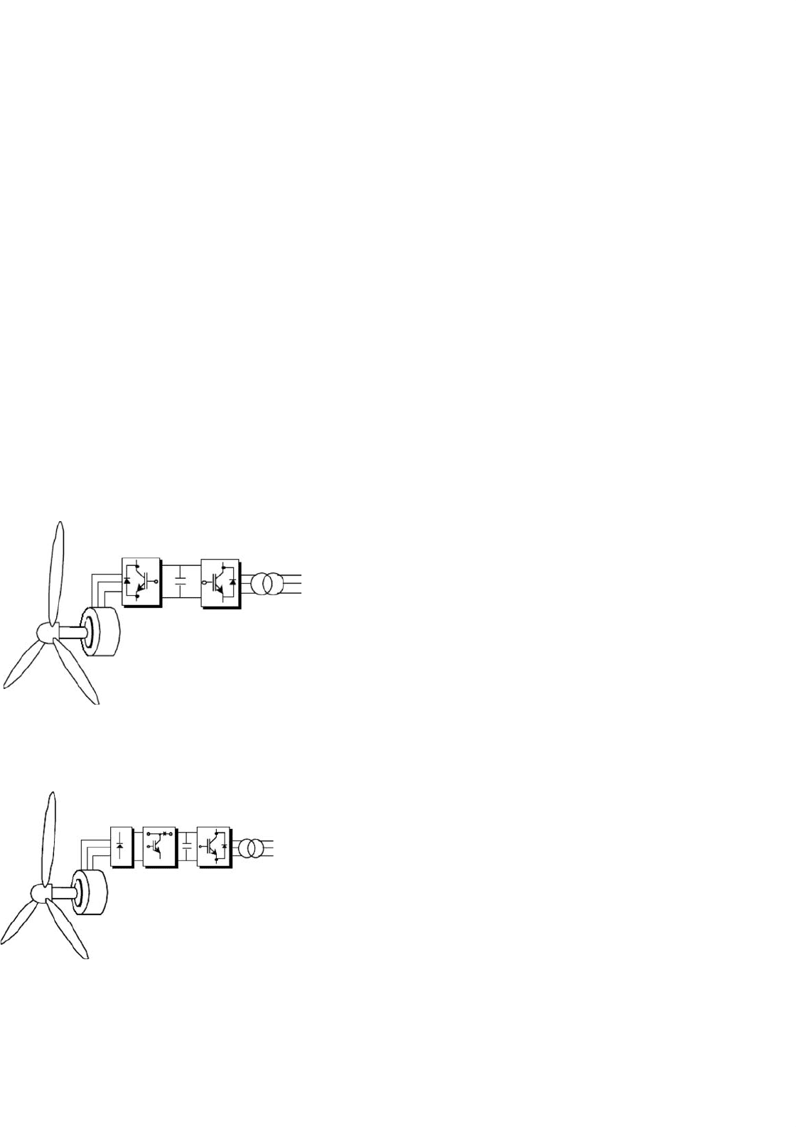
27.3.6.5.2 Permanent Magnet Synchronous Generators
The permanent magnet synchronous generator (PMSG) has
several significant advantageous properties. The construction
is simple and does not required external magnetization, which
is important especially in stand-alone wind power applications
and also in remote areas where the grid cannot easily supply
the reactive power required to magnetize the induction gener-
ator. Similar to the previous externally supplied field current
synchronous generator, the most common type of power con-
version uses a bridge rectifier (controlled/uncontrolled), a DC
link, and inverter as shown in Fig. 27.65 [78–80].
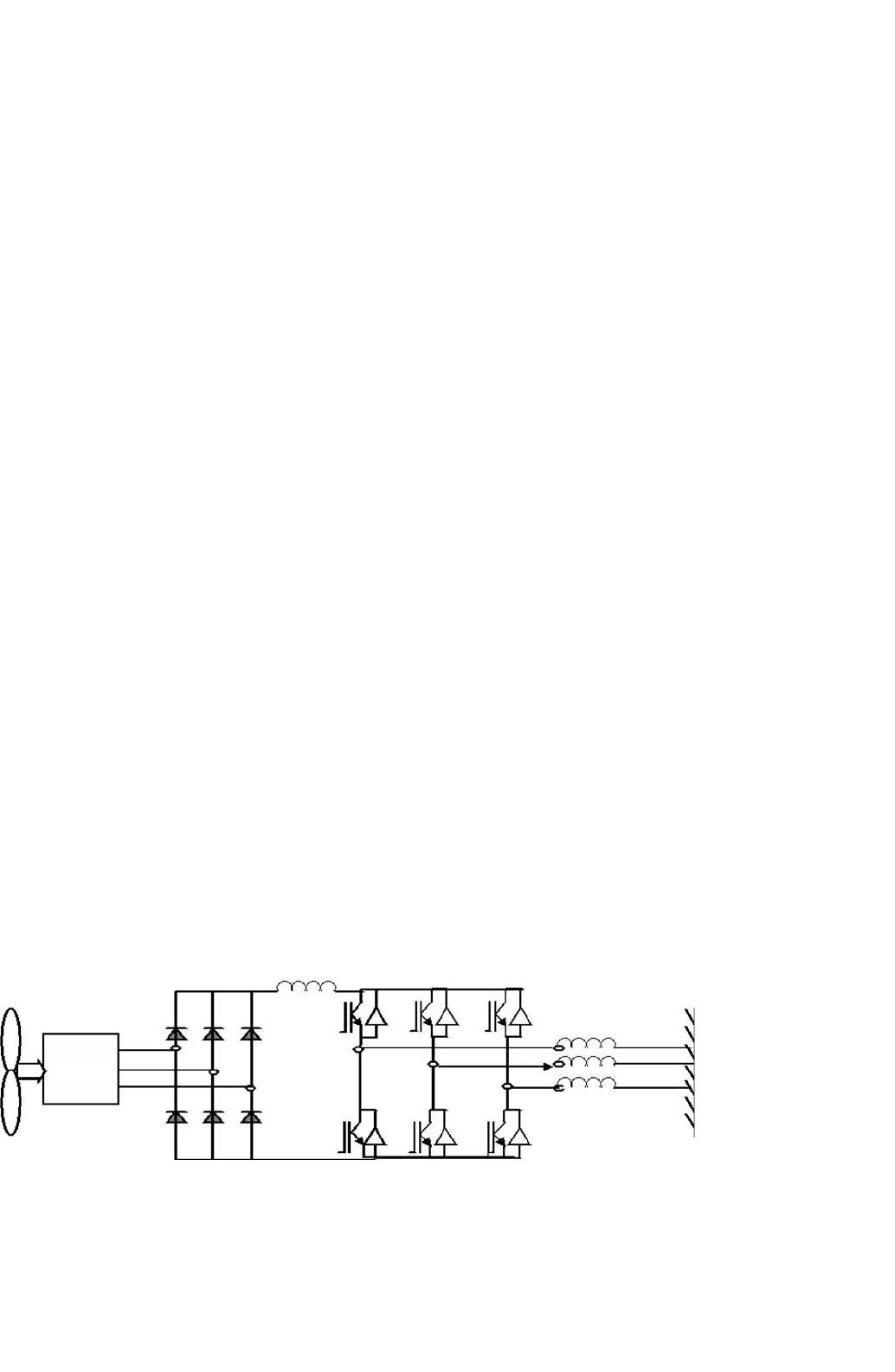
Figure 27.66 shows a wind energy system where a PMSG
is connected to a three-phase rectifier followed by a boost
converter. In this case, the boost converter controls the elec-
tromagnet torque and the supply side converter regulates the
DC link voltage as well as controlling the input power fac-
tor. One drawback of this configuration is the use of diode
Utility grid
FIGURE 27.65 Grid-connected PMSG wind energy system through
DC/AC converter.
Utility grid
FIGURE 27.66 Grid-connected PMSG wind energy system through
DC/AC converter with a boost chopper.
rectifier that increases the current amplitude and distortion of
the PMSG. As a result, this configuration have been consid-
ered for small size wind energy conversion systems (smaller
than 50 kW).
The advantage of the system in Fig. 27.65 with regardant to
the system showed in Fig. 27.66 is, it allows the generator to
operate near its optimal working point in order to minimize
the losses in the generator and power electronic circuit. How-
ever, the performance is dependent on the good knowledge
of the generator parameter that varies with temperature and
frequency. The main drawbacks, in the use of PMSG, are the
cost of permanent magnet that increase the price of machine,
demagnetization of the permanent magnet material, and it is
not possible to control the power factor of the machine
To extract maximum power at unity power factor from a
PMSG and feed this power (also at unity power factor) to
the grid, the use of back-to-back connected PWM voltage
source converters are proposed [81]. Moreover, to reduce the
overall cost, reduced switch PWM voltage source converters
(four switch) instead of conventional (six switch) converters
for variable speed drive systems can be used. It is shown that by
using both rectifier and inverter current control or flux based
control, it is possible to obtain unity power factor operation
both at the WTG and the grid. Other mechanisms can also
be included to maximize power extraction from the VSWT
(i.e. MPPT techniques) or sensor-less approaches to further
reduce cost and increase reliability and performance of the
systems.
27.3.6.5.3 Squirrel-cage Induction Generator Possible archi-
tecture for systems using conventional induction generators
which have a solid squirrel-cage rotor have many similarities
to those with synchronous generators. The main difference
is that the induction generator is not inherently self-exciting
and it needs a source of reactive power. This could be done
by a generator side self-commutated converter operating in
the rectifier mode. A significant advantage of this configu-
ration is the low cost and low maintenance requirements of
induction generators. Another advantage of using the self-
commutated double converter is that it can be on the ground,
completely separate from the wind machine. If there is a
problem in the converter, it could be switched out of the
circuit for repair and the wind machine could continue to
run at constant speed. The main disadvantage with this con-
figuration is that, as with the synchronous generator, the
power conversion system would have to take the full power
generated and could be relatively costly compared to some
other configurations. There would also be additional com-
plexities associated with the supply of reactive power to the
generator.
27.3.6.5.4 Wound Rotor Induction Generator A wound
rotor induction rotor has three-phase winding on the rotor,
27 Power Electronics for Renewable Energy Sources 713
accessible to the outside via slip rings. The possibility of
accessing the rotor can have the following configurations:
• Slip power recovery.
• Use of cycloconverter.
• Rotor resistance chopper control.
A. Slip Power Recovery (Static Kramer System)
The slip power recovery configuration behaves similarly to a
conventional induction generator with very large slip, but in
addition energy is recovered from the rotor. The rotor power
is first carried out through slip rings, then rectified and passed
through a DC link to a line-commutated inverter and into the
grid. The rest of the power comes directly from the stator as
it normally does. A disadvantage with this system is that it
can only allow super-synchronous variable speed operation.
Its possible use in the wind power was reported by Smith and
Nigim [82].
In this scheme shown in Fig. 27.67, the stator is directly
connected to the grid. Power converter has been connected to
the rotor of wound rotor induction generator to obtain the
optimum power from variable speed wind turbine. The main
advantage of this scheme is that the power-conditioning unit
has to handle only a fraction of the total power so as to obtain
full control of the generator. This is very important when the
wind turbine sizes are increasing for the grid-connected appli-
cations for higher penetration of wind energy and the smaller
size of converter can be used in this scheme.
B. Cycloconverter (Static Scherbius System)
A cycloconverter is a converter, which converts AC voltage
of one frequency to another frequency without an intermedi-
ate DC link. When a cycloconverter is connected to the rotor
circuit, sub- and super-synchronous operation variable speed
operation is possible. In super-synchronous operation, this
configuration is similar to the slip power recovery. In addition,
energy may be fed into the rotor, thus allowing the machine
to generate at sub-synchronous speeds. For that reason, the
generator is said to be doubly fed [83]. This system has a
Wind
Turbine
DOIG
(Double
output
Induction
Generator)
Filter
Converter
Line
filter
Transformer
Grid
FIGURE 27.67 Schematic diagram of doubly-fed induction generator.
limited ability to control reactive power at the terminals of
the generator, although as a whole it is a net consumer of
reactive power. On the other hand, if coupled with capaci-
tor excitation, this capability could be useful from the utility
point of view. Because of its ability to rapidly adjust phase
angle and magnitude of the terminal voltage, the generator can
be resynchronized after a major electrical disturbance with-
out going through a complete stop/start sequence. With some
wind turbines, this could be a useful feature.
C. Rotor Resistance Chopper Control
A fairly simple scheme of extracting rotor power as in the form
of heat has been proposed in [44].
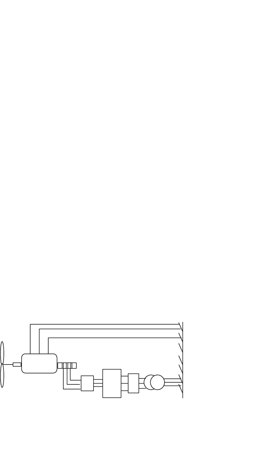
27.3.6.6 Isolated Grid Supply System with Multiple
Wind Turbines
The isolated grid supply system with a wind park is shown in
Fig. 27.68. Two or more wind turbines can be connected to this
system. A diesel generator can be connected in parallel. The
converters, connected with wind generators will work in paral-
lel and the supervisory control block will control the output of
these wind generators in conjunction with the diesel generator.
This type of decentralized generation can be a better option
where high penetration of wind generation is sought. The indi-
vidual converter will control the voltage and frequency of the
system. The supervisory control system will play an impor-
tant part in co-ordination between multiple power generation
systems in a remote area power supply having weak grid.
27.3.6.7 Power Electronics Technology Development
To meet the needs of future power generation systems, power
electronics technology will need to evolve on all levels, from
devices to systems. The development needs are as follows:
• There is a need for modular power converters with plug-
and-play controls. This is particularly important for high
power utility systems, such as wind power. The power