Power electronic handbook
Подождите немного. Документ загружается.

684 C. V. Nayar et al.
PV Panel
PCU
DC Motor-Pump
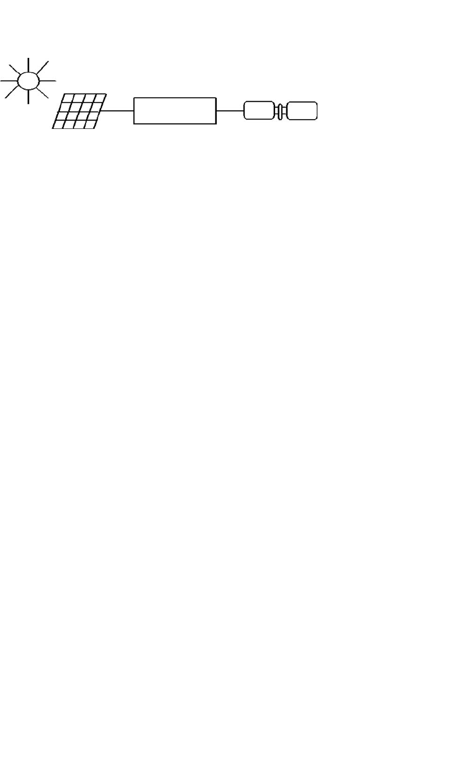
FIGURE 27.24 Block diagram for DC motor driven pumping scheme.
27.2.3.3.3 Power Conditioning Units for PV Water Pumping
Most PV pump manufacturers include power conditioning
units (PCU) which are used for operating the PV panels close
to their MPP over a range of load conditions and varying
insolation levels and also for power conversion. DC or AC
motor-pump units can be used for PV water pumping. In
its simplest form, a solar water pumping system comprises
of PV array, PCU, and DC water-pump unit as shown in
Fig. 27.24.
In case of lower light levels, high currents can be gen-
erated through power conditioning to help in starting the
motor-pump units especially for reciprocating positive dis-
placement type pumps with constant torque characteristics,
requiring constant current throughout the operating region.
In positive displacement type pumps, the torque generated by
the pumps depends on the pumping head, friction, and pipe
diameter etc. and needs certain level of current to produce
the necessary torque. Some systems use electronic controllers
to assist starting and operation of the motor under low solar
radiation. This is particularly important when using positive
displacement pumps. The solar panels generate DC voltage
and current. The solar water pumping systems usually has DC
or AC pumps. For DC pumps, the PV output can be directly
connected to the pump through MPPT or a DC–DC con-
verter can also be used for interfacing for controlled DC output
from PV panels. To feed the AC motors, a suitable interfac-
ing is required for the power conditioning. These PV inverters
for the stand-alone applications are very expensive. The aim
of power conditioning equipment is to supply the controlled
voltage/current output from the converters/inverters to the
motor-pump unit.
These power-conditioning units are also used for operating
the PV panels close to their maximum efficiency for fluctuat-
ing solar conditions. The speed of the pump is governed by
the available driving voltage. Current lower than the acceptable
limit will stop the pumping. When the light level increases, the
operating point will shift from the MPP leading to the reduc-
tion of efficiency. For centrifugal pumps, there is an increase
in current at increased speed and the matching of I–V char-
acteristics is closer for wide range of light intensity levels. For
centrifugal pumps, the torque is proportional to the square
of speed and the torque produced by the motors is propor-
tional to the current. Due to decrease in PV current output,
the torque from the motor and consequently the speed of the
pump is reduced resulting in decrease in back emf and the
required voltage of the motor. Maximum power point tracker
can be used for controlling the voltage/current outputs from
the PV inverters to operate the PV close to maximum oper-
ating point for the smooth operation of motor-pump units.
The DC–DC converter can be used for keeping the PV pan-
els output voltage constant and help in operating the solar
arrays close to MPP. In the beginning, high starting current is
required to produce high starting torque. The PV panels can-
not supply this high starting current without adequate power
conditioning equipment like DC–DC converter or by using
a starting capacitor. The DC–DC converter can generate the
high starting currents by regulating the excess PV array voltage.
DC–DC converter can be boost or buck converter.
Brush-less DC motor (BDCM) and helical rotor pumps can
also be used for PV water pumping [36]. Brush-less DC motors
are a self synchronous type of motor characteristics by trape-
zoidal waveforms for back emf and air flux density. They can
operate off a low voltage DC supply which is switched through
an inverter to create a rotating stator field. The current gen-
eration of BDCMs use rare earth magnets on the rotor to
give high air gap flux densities and are well suited to solar
application. The block diagram of such an arrangement is
shown in Fig. 27.25 which consists of PV panels, DC–DC
converter, MPPT, and BDCM.
The PV inverters are used to convert the DC output of the
solar arrays to the AC quantity so as to run the AC motors
driven pumps. These PV inverters can be variable frequency
type, which can be controlled to operate the motors over
wide range of loads. The PV inverters may involve impedance
matching to match the electrical characteristics of the load
and array. The motor-pump unit and PV panels operate at
their maximum efficiencies. Maximum power point tracker is
also used in the power conditioning. To keep the voltage sta-
ble for the inverters, the DC–DC converter can be used. The
inverter/converter has a capability of injecting high-switch fre-
quency components, which can lead to the overheating and the
losses. So care shall be taken for this. The PV arrays are usually
connected in series, parallel, or a combination of series parallel,
configurations. The function of power electronic interface, as
mentioned before, is to convert the DC power from the array
to the required voltage and frequency to drive the AC motors.
27 Power Electronics for Renewable Energy Sources 685
Rotor positioning sensing
PV array
MPPT
Max power point tracker
Brushless
DC motor
BDCP
a
b
c
Positive
displacement
pump
Pump
DC-DC
converter
BDC Motor
controller
+
−
FIGURE 27.25 Block diagram for BDCM for PV application.
PV panel
3 phase Inverter
without step-up
transformer
3 phase step-up
transformer
Low voltage
AC motor
Motor-pump
Mains voltage
AC motor
Mains voltage
AC motor
Motor-pump
DC to DC
converter
(a)
(b)
(c)
Motor-pump
3 phase
Inverter
3 phase
Inverter
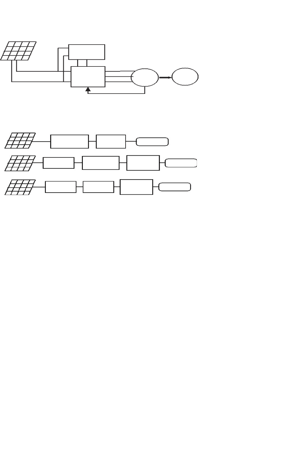
FIGURE 27.26 Block diagrams for various AC motor driven pumping schemes.
The motor-pump system load should be such that the array
operates close to it’s MPP at all solar insolation levels. There
are mainly three types solar powered water pumping systems
as shown in Fig. 27.26.
The first system shown in Fig. 27.26a is an imported com-
mercially available unit, which uses a specially wound low
voltage induction motor driven submersible pump. Such a low
voltage motor permits the PV array voltage to be converted to
AC without using a step-up transformer. The second system,
shown in Fig. 27.26b makes use of a conventional “off-the-
shelf” 415 V, 50 Hz, induction motor [6]. This scheme needs
a step-up transformer to raise inverter output voltage to high
voltage. Third scheme as shown in Fig. 27.26c comprises of a
DC–DC converter, an inverter that switches at high frequency,
and a mains voltage motor driven pump. To get the optimum
discharge (Q), at a given insolation level, the efficiency of the
DC–DC converter and the inverter should be high. So the pur-
pose should be to optimize the output from PV array, motor,
and the pump. The principle used here is to vary the duty
cycle of a DC–DC converter so that the output voltage is max-
imum. The DC–DC converter is used to boost the solar array
voltage to eliminate the need for a step-up transformer and
operate the array at the MPP. The three-phase inverter used
in the interface is designed to operate in a variable frequency
mode over the range of 20–50 Hz, which is the practical limit
for most 50 Hz induction motor applications. Block diagram
for frequency control is given in Fig. 27.27.
This inverter would be suitable for driving permanent
magnet motors by incorporating additional circuitry for posi-
tion sensing of the motor’s shaft. Also the inverter could
be modified, if required, to produce higher output frequen-
cies for high-speed permanent magnet motors. The inverter
has a three-phase full-bridge configuration implemented by
MOSFET power transistors.
27.2.4 Hybrid Energy Systems
The combination of RES, such as PV arrays or wind turbines,
with engine-driven generators and battery storage, is widely
recognized as a viable alternative to conventional remote area
power supplies (RAPS). These systems are generally classified
as hybrid energy systems (HES). They are used increasingly for
electrification in remote areas where the cost of grid extension
is prohibitive and the price for fuel increases drastically with
the remoteness of the location. For many applications, the
combination of renewable and conventional energy sources
compares favorably with fossil fuel-based RAPS systems, both
in regard to their cost and technical performance. Because
these systems employ two or more different sources of energy,
they enjoy a very high degree of reliability as compared to
single-source systems such as a stand-alone diesel generator
or a stand-alone PV or wind system. Applications of hybrid
energy systems range from small power supplies for remote
686 C. V. Nayar et al.
Motor
Pump
Voltage
Frequency
Control
Processor
Converter
Inverter
PV Panel
FIGURE 27.27 Block diagram for voltage/frequency control.
households, providing electricity for lighting and other essen-
tial electrical appliances, to village electrification for remote
communities has been reported [37].
Hybrid energy systems generate AC electricity by com-
bining RES such as PV array with an inverter, which can
operate alternately or in parallel with a conventional engine-
driven generator. They can be classified according to their
configuration as [38]:
•
Series hybrid energy systems.
• Switched hybrid energy systems.
• Parallel hybrid energy systems.
The parallel hybrid systems can be further divided to DC
or AC coupling. An overview of the three most common
system topologies is presented by Bower [39]. In the follow-
ing comparison of typical PV-diesel system configurations are
described.
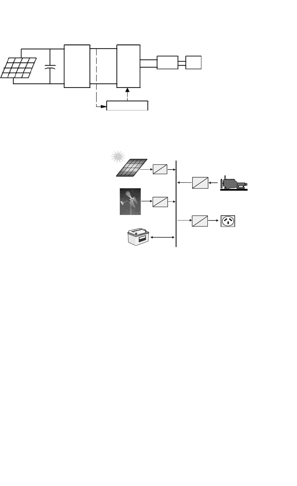
27.2.4.1 Series Configuration
In the conventional series hybrid systems shown in Fig. 27.28,
all power generators feed DC power into a battery. Each com-
ponent has therefore to be equipped with an individual charge
controller and in the case of a diesel generator with a rectifier.
To ensure reliable operation of series hybrid energy systems
both the diesel generator and the inverter have to be sized
to meet peak loads. This results in a typical system operation
where a large fraction of the generated energy is passed through
the battery bank, therefore resulting in increased cycling of the
battery bank and reduced system efficiency. AC power deliv-
ered to the load is converted from DC to regulated AC by
an inverter or a motor generator unit. The power generated
by the diesel generator is first rectified and subsequently con-
verted back to AC before being supplied to the load, which
incurs significant conversion losses.
The actual load demand determines the amount of electrical
power delivered by the PV array, wind generator, the battery
bank, or the diesel generator. The solar and wind charger pre-
vents overcharging of the battery bank from the PV generator
PV Array
Battery Bank
Diesel Generator
AC Load
=
~
Battery Charger
Inverter
DC BUS
Solar Charger
=
=
=
~
Wind
Generator
=
Wind Charger
~
~
~
FIGURE 27.28 Series hybrid energy system.
when the PV power exceeds the load demand and the batter-
ies are fully charged. It may include MPPT to improve the
utilization of the available PV energy, although the energy
gain is marginal for a well-sized system. The system can be
operated in manual or automatic mode, with the addition of
appropriate battery voltage sensing and start/stop control of
the engine-driven generator.
Advantages:
• The engine-driven generator can be sized to be optimally
loaded while supplying the load and charging the battery
bank, until a battery SOC of 70–80% is reached.
•
No switching of AC power between the different energy
sources is required, which simplifies the electrical output
interface.
• The power supplied to the load is not interrupted when
the diesel generator is started.
• The inverter can generate a sine-wave, modified square-
wave, or square-wave depending on the application.
27 Power Electronics for Renewable Energy Sources 687
Disadvantages:
• The inverter cannot operate in parallel with the engine-
driven generator, therefore the inverter must be sized to
supply the peak load of the system.
• The battery bank is cycled frequently, which shortens its
lifetime.
• The cycling profile requires a large battery bank to
limit the depth-of-discharge (DOD).
• The overall system efficiency is low, since the diesel
cannot supply power directly to the load.
•
Inverter failure results in complete loss of power to the
load, unless the load can be supplied directly from the
diesel generator for emergency purposes.
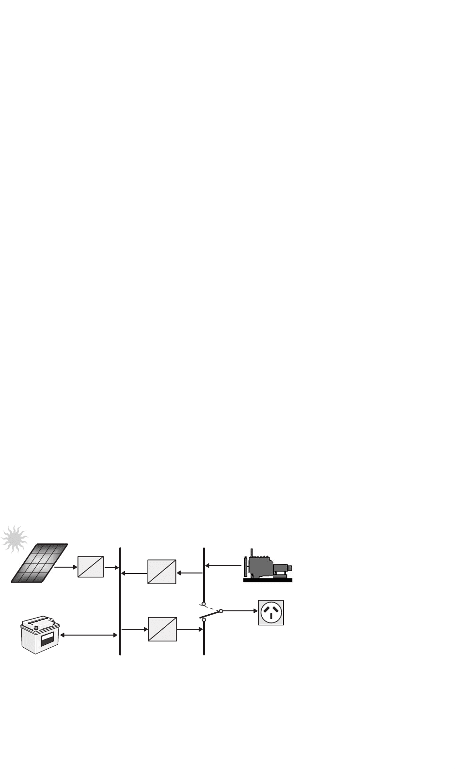
27.2.4.2 Switched Configuration
Despite its operational limitations, the switched configura-
tion remains one of the most common installations in some
developing countries. It allows operation with either the
engine-driven generator or the inverter as the AC source,
yet no parallel operation of the main generation sources
is possible. The diesel generator and the RES can charge
the battery bank. The main advantage compared with the
series system is that the load can be supplied directly by the
engine-driven generator, which results in a higher overall con-
version efficiency. Typically, the diesel generator power will
exceed the load demand, with excess energy being used to
recharge the battery bank. During periods of low electric-
ity demand the diesel generator is switched off and the load
is supplied from the PV array together with stored energy.
Switched hybrid energy systems can be operated in manual
mode, although the increased complexity of the system makes
it highly desirable to include an automatic controller, which
can be implemented with the addition of appropriate battery
voltage sensing and start/stop control of the engine-driven
generator (Fig. 27.29).
PV Array
Battery Bank
Diesel Generator
AC Load
=
~
Battery Charger
Inverter
DC BUS
Solar Controller
=
=
=
~
AC BUS
1
2
change-over
switch
FIGURE 27.29 Switched PV-diesel hybrid energy system.
Advantages:
• The inverter can generate a sine-wave, modified square-
wave, or square-wave, depending on the particular
application.
• The diesel generator can supply the load directly, there-
fore improving the system efficiency and reducing the
fuel consumption.
Disadvantages:
• Power to the load is interrupted momentarily when the
AC power sources are transferred.
• The engine-driven alternator and inverter are typically
designed to supply the peak load, which reduces their
efficiency at part load operation.
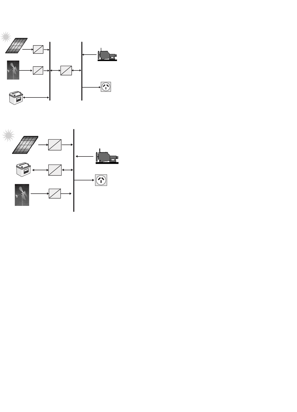
27.2.4.3 Parallel Configuration
The parallel hybrid system can be further classified as DC
and AC couplings as shown in Fig. 27.30. In both schemes,
a bi-directional inverter is used to link between the battery
and an AC source (typically the output of a diesel genera-
tor). The bi-directional inverter can charge the battery bank
(rectifier operation) when excess energy is available from the
diesel generator or by the renewable sources, as well as act as
a DC–AC converter (inverter operation). The bi-directional
inverter may also provide “peak shaving” as part of a control
strategy when the diesel engine is overloaded. In Fig. 27.30a,
the renewable energy sources (RES) such as photovoltaic and
wind are coupled on the DC side. DC integration of RES
results in “custom” system solutions for individual supply
cases requiring high costs for engineering, hardware, repair,
and maintenance. Furthermore, power system expandability
for covering needs of growing energy and power demand is
also difficult. A better approach would be to integrate the
RES on the AC side rather than on the DC side as shown
in Fig. 27.30b.
688 C. V. Nayar et al.
PV Array
Battery Bank
Diesel Generator
Bi-directional
Inverter
DC BUS
Solar Charger
=
=
=
~
AC BUS
Wind
Generator
Wind Charger
=
~
~
~
(a)
Battery Bank
Diesel Generator
AC Load
AC Load
Bi-directional
Inverter
PV Inverter
=
~
AC BUS
Wind Inverter
PV Array
Wind
Generator
~
~
~
~
=
~
(b)
FIGURE 27.30 Parallel PV-diesel hybrid energy system: (a) DC decou-
pling and (b) AC coupling.
Parallel hybrid energy systems are characterized by two sig-
nificant improvements over the series and switched system
configuration.
The inverter plus the diesel generator capacity rather than
their individual component ratings limit the maximum load
that can be supplied. Typically, this will lead to a doubling of
the system capacity. The capability to synchronize the inverter
with the diesel generator allows greater flexibility to optimize
the operation of the system. Future systems should be sized
with a reduced peak capacity of the diesel generator, which
results in a higher fraction of directly used energy and hence
higher system efficiencies.
By using the same power electronic devices for both inverter
and rectifier operation, the number of system components is
minimized. Additionally, wiring and system installation costs
are reduced through the integration of all power-conditioning
devices in one central power unit. This highly integrated sys-
tem concept has advantages over a more modular approach to
system design, but it may prevent convenient system upgrades
when the load demand increases.
The parallel configuration offers a number of potential
advantages over other system configurations. These objectives
can only be met if the interactive operation of the individual
components is controlled by an “intelligent” hybrid energy
management system. Although today’s generation of parallel
systems include system controllers of varying complexity and
sophistication, they do not optimize the performance of the
complete system. Typically, both the diesel generator and the
inverter are sized to supply anticipated peak loads. As a result
most parallel hybrid energy systems do not utilize their capa-
bility of parallel, synchronized operation of multiple power
sources.
Advantages:
• The system load can be met in an optimal way.
• Diesel generator efficiency can be maximized.
• Diesel generator maintenance can be minimized.
• A reduction in the rated capacities of the diesel gener-
ator, battery bank, inverter, and renewable resources is
feasible, while also meeting the peak loads.
Disadvantages:
• Automatic control is essential for the reliable operation
of the system.
• The inverter has to be a true sine-wave inverter with the
ability to synchronize with a secondary AC source.
• System operation is less transparent to the untrained user
of the system.
27.2.4.4 Control of Hybrid Energy Systems
The design process of hybrid energy systems requires
the selection of the most suitable combination of energy
sources, power-conditioning devices, and energy storage sys-
tem together with the implementation of an efficient energy
dispatch strategy. System simulation software is an essential
tool to analyze and compare possible system combinations.
The objective of the control strategy is to achieve optimal
operational performance at the system level. Inefficient opera-
tion of the diesel generator and “dumping” of excess energy is
common for many RAPS, operating in the field. Component
maintenance and replacement contributes significantly to the
lifecycle cost of systems. These aspects of system operation are
clearly related to the selected control strategy and have to be
considered in the system design phase.
Advanced system control strategies seek to reduce the num-
ber of cycles and the DOD for the battery bank, run the
diesel generator in its most efficient operating range, max-
imize the utilization of the renewable resource, and ensure
high reliability of the system. Due to the varying nature
of the load demand, the fluctuating power supplied by the
photovoltaic generator, and the resulting variation of bat-
tery SOC, the hybrid energy system controller has to respond
27 Power Electronics for Renewable Energy Sources 689
0
2
4
6
8
10
12
14
16
18
20
22
24
Hourly Load
PV Energy
Diesel Energy
0
20
40
60
80
100
120
Rated Capacity (%)
Hour
Battery/Inverter
PV
Battery/Inverter
DG
Load
(I)
(II)
(III)
(IV)
(V)
(VI)
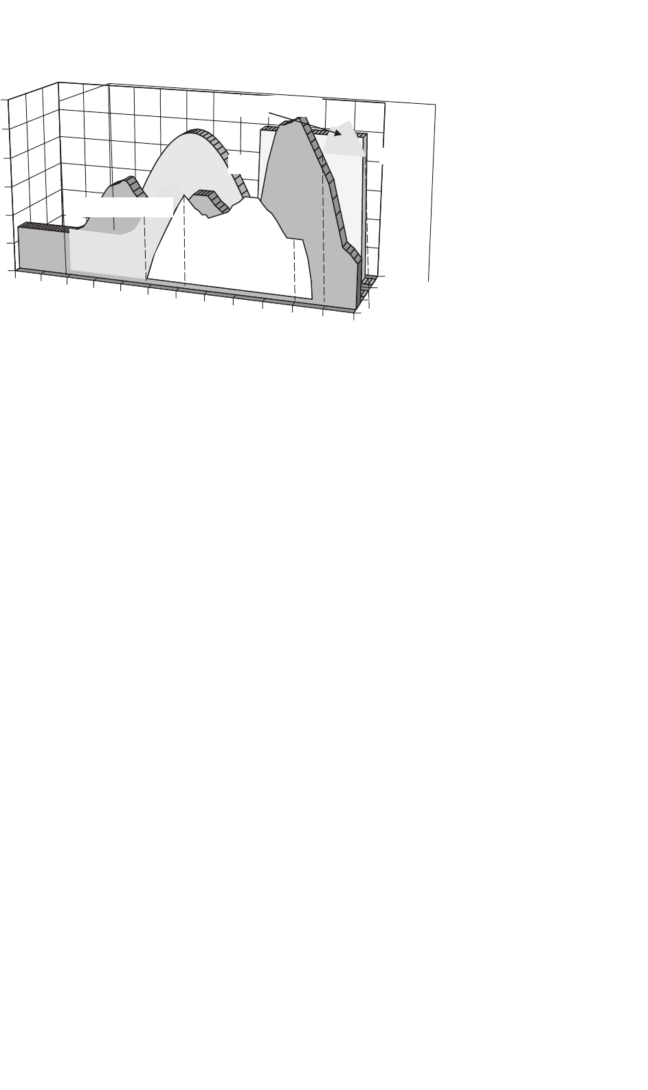
FIGURE 27.31 Operating modes for a PV single-diesel hybrid energy system.
to continuously changing operating conditions. Figure 27.31
shows different operating modes for a PV single-diesel system
using a typical diesel dispatch strategy.
Mode (I): The base load, which is typically experienced at night-
time and during the early morning hours, is supplied by
energy stored in the batteries. Photovoltaic power is not
available and the diesel generator is not started.
Mode (II): PV power is supplemented by stored energy to meet
the medium load demand.
Mode (III): Excess energy is available from the PV generator,
which is stored in the battery. The medium load demand is
supplied from the PV generator.
Mode (IV): The diesel generator is started and operated at its
nominal power to meet the high evening load. Excess energy
available from the diesel generator is used to recharge the
batteries.
Mode (V): The diesel generator power is insufficient to meet the
peak load demand. Additional power is supplied from the
batteries by synchronizing the inverter AC output voltage
with the alternator waveform.
Mode (VI): The diesel generator power exceeds the load demand,
but it is kept operational until the batteries are recharged
to a high SOC level.
In principle, most efficient operation is achieved if the gen-
erated power is supplied directly to the load from all energy
sources, which also reduces cycling of the battery bank. How-
ever, since diesel generator operation at light loads is inherently
inefficient, it is common practice to operate the engine-driven
generator at its nominal power rating and to recharge the
batteries from the excess energy. The selection of the most
efficient control strategy depends on fuel, maintenance and
component replacement cost, the system configuration, envi-
ronmental conditions, as well as constraints imposed on the
operation of the hybrid energy system.
27.2.5 Grid-connected PV Systems
The utility interactive inverters not only conditions the power
output of the PV arrays but ensures that the PV system out-
put is fully synchronized with the utility power. These systems
can be battery less or with battery backup. Systems with bat-
tery storage (or flywheel) provide additional power supply
reliability. The grid connection of PV systems is gathering
momentum because of various rebate and incentive schemes.
This system allows the consumer to feed its own load utiliz-
ing the available solar energy and the surplus energy can be
injected into the grid under the energy by back scheme to
reduce the payback period. Grid-connected PV systems can
become a part of the utility system. The contribution of solar
power depends upon the size of system and the load curve
of the house. When the PV system is integrated with the
utility grid, a two-way power flow is established. The util-
ity grid will absorb excess PV power and will feed the house
during nighttime and at instants while the PV power is inad-
equate. The utility companies are encouraging this scheme in
many parts of the world. The grid-connected system can be
classified as:
• Rooftop application of grid-connected PV system.
• Utility scale large system.
For small household PV applications, a roof mounted PV
array can be the best option. Solar cells provide an environ-
mentally clean way of producing electricity, and rooftops have
always been the ideal place to put them. With a PV array
on the rooftop, the solar generated power can supply resi-
dential load. The rooftop PV systems can help in reducing
the peak summer load to the benefit of utility companies by
feeding the household lighting, cooling, and other domestic
loads. The battery storage can further improve the reliability
of the system at the time of low insolation level, nighttime,

690 C. V. Nayar et al.
or cloudy days. But the battery storage has some inherent
problems like maintenance and higher cost.
For roof-integrated applications, the solar arrays can be
either mounted on the roof or directly integrated into the roof.
If the roof integration does not allow for an air channel behind
the PV modules for ventilation purpose, then it can increase
the cell temperature during the operation consequently lead-
ing to some energy losses. The disadvantage with the rooftop
application is that the PV array orientation is dictated by the
roof. In case, when the roof orientation differs from the opti-
mal orientation required for the cells, then efficiency of the
entire system would be suboptimal.
Utility interest in PV has centered on the large grid-
connected PV systems. In Germany, USA, Spain, and in several
other parts of the world, some large PV scale plants have been
installed. The utilities are more inclined with large scale, cen-
tralized power supply. The PV systems can be centralized or
distributed systems.
Grid-connected PV systems must observe the islanding sit-
uation, when the utility supply fails. In case of islanding, the
PV generators should be disconnected from mains. PV gener-
ators can continue to meet only the local load, if the PV output
matches the load. If the grid is re-connected during islanding,
transient overcurrents can flow through the PV system invert-
ers and the protective equipments like circuit breakers may
be damaged. The islanding control can be achieved through
inverters or via the distribution network. Inverter controls
can be designed on the basis of detection of grid voltage,
measurement of impedance, frequency variation, or increase
in harmonics. Protection shall be designed for the islanding,
short circuits, over/under-voltages/currents, grounding, and
lightening, etc.
The importance of the power generated by the PV system
depends upon the time of the day specially when the utility is
experiencing the peak load. The PV plants are well suited to
summer peaking but it depends upon the climatic condition
of the site. PV systems being investigated for use as peaking
stations would be competitive for load management. The PV
users can defer their load by adopting load management to
get the maximum benefit out of the grid-connected PV plants
and feeding more power into the grid at the time of peak
load.
The assigned capacity credit is based on the statistical prob-
ability with which the grid can meet peak demand [4]. The
capacity factor during the peaks is very similar to that of con-
ventional plants and similar capacity credit can be given for
the PV generation except at the times when the PV plants
are generating very less power unless adequate storage is pro-
vided. With the installation of PV plants, the need of extra
transmission lines, transformers can be delayed or avoided.
The distributed PV plants can also contribute in providing
reactive power support to the grid and reduce burden on VAR
compensators.
27.2.5.1 Inverters for Grid-connected Applications
Power conditioner is the key link between the PV array and
mains in the grid-connected PV system. It acts as an interface
that converts DC current produced by the solar cells into util-
ity grade AC current. The PV system behavior relies heavily
on the power-conditioning unit. The inverters shall produce
good quality sine-wave output. The inverter must follow the
frequency and voltage of the grid and the inverter has to extract
maximum power from the solar cells with the help of MPPT
and the inverter input stage varies the input voltage until the
MPP on the I–V curve is found. The inverter shall monitor
all the phases of the grid. The inverter output shall be con-
trolled in terms of voltage and frequency variation. A typical
grid-connected inverter may use a PWM scheme and operates
in the range of 2–20 kHz.
27.2.5.2 Inverter Classifications
The inverters used for the grid interfacing are broadly classi-
fied as:
•
Voltage source inverters (VSI).
• Current source inverters (CSI).
Whereas the inverters based on the control schemes can be
classified as:
• Current controlled (CC).
• Voltage controlled (VC).
The source is not necessarily characterized by the energy
source for the system. It is a characteristic of the topology of
the inverter. It is possible to change from one source type to
another source type by the addition of passive components.
In the voltage source inverter (VSI), the DC side is made to
appear to the inverter as a voltage source. The VSIs have a
capacitor in parallel across the input whereas the CSIs have
an inductor is series with the DC input. In the CSI, the DC
source appears as a current source to the inverter. Solar arrays
are fairly good approximation to a current source. Most PV
inverters are voltage source even though the PV is a current
source. Current source inverters are generally used for large
motor drives though there have been some PV inverters built
using a current source topology. The VSI is more popular with
the PWM VSI dominating the sine-wave inverter topologies.
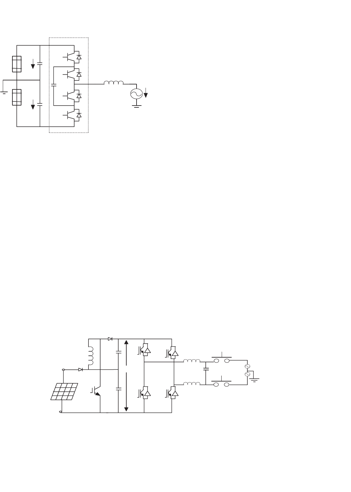
Figure 27.32a shows a single-phase full-bridge bi-directional
VSI with (a) voltage control and phase-shift (δ) control –
voltage-controlled voltage source inverter (VCVSI). The active
power transfer from the PV panels is accomplished by con-
trolling the phase angle δ between the converter voltage and
the grid voltage. The converter voltage follows the grid volt-
age. Figure 27.32b shows the same VSI operated as a current
controlled (CCVSI). The objective of this scheme is to control
active and reactive components of the current fed into the grid
using PWM techniques.
27 Power Electronics for Renewable Energy Sources 691
I
ref
Φ
(a)
X
1
X
2
Q
1
Q
2
Q
3
Q
4
C
1
C
2
Transformer
Load
Grid
PV array
I
inv
(b)
Inductor
X
L
X
1
X
2
Q
1
Q
2
Q
3
Q
4
C
1
C
2
Transformer
Grid
Load
PV array
Control System
Control System
V
g
d
V
inv
0
FIGURE 27.32 Voltage source inverter: (a) voltage control and (b) cur-
rent control.
27.2.5.3 Inverter Types
Different types are being in use for the grid-connected PV
applications such as:
• Line-commutated inverter.
• Self-commutated inverter.
• Inverter with high-frequency transformer.
27.2.5.3.1 Line-commutated Inverter The line-commutated
inverters are generally used for the electric motor applications.
The power stage is equipped with thyristors. The maximum
PV Array
V
dc
240 V
ac
+
−
Grid
FIGURE 27.33 Line-commuted single-phase inverter.
power tracking control is required in the control algorithm
for solar application. The basic diagram for a single-phase line-
commutated inverter is shown in the Fig. 27.33 [3].
The driver circuit has to be changed to shift the firing angle
from the rectifier operation (0 <φ<90) to inverter operation
(90 <φ<180). Six-pulse or 12-pulse inverter are used for the
grid interfacing but 12-pulse inverters produce less harmon-
ics. The thysistor type inverters require a low impedance grid
interface connection for commutation purpose. If the maxi-
mum power available from the grid connection is less than
twice the rated PV inverter power, then the line-commutated
inverter should not be used [3]. The line-commutated invert-
ers are cheaper but inhibits poor power quality. The harmonics
injected into the grid can be large unless taken care of by
employing adequate filters. These line-commutated inverters
also have poor power factor, poor power quality, and need
additional control to improve the power factor. Transformer
can be used to provide the electrical isolation. To suppress
the harmonics generated by these inverters, tuned filters are
employed and reactive power compensation is required to
improve the lagging power factor.
27.2.5.3.2 Self-commutated Inverter A switch mode inverter
using pulse width modulated (PWM) switching control, can
be used for the grid connection of PV systems. The basic block
diagram for this type of inverter is shown in the Fig. 27.34.
The inverter bridges may consist of bipolar transistors, MOS-
FET transistors, IGBT’s, or gate turn-off thyristor’s (GTO’s),
depending upon the type of application. GTO’s are used for
the higher power applications, whereas IGBT’s can be switched
at higher frequencies i.e. 16 kHz, and are generally used for
many grid-connected PV applications. Most of the present day
inverters are self-commutated sine-wave inverters.
Based on the switching control, the voltage source inverters
can be further classified based on the switching control as:
• PWM (pulse width modulated) inverters.
• Square-wave inverters.
•
Single-phase inverters with voltage cancellations.
• Programmed harmonic elimination switching.
• Current controlled modulation.
692 C. V. Nayar et al.
S
1
S
3
S
5
S
2
S
4
S
6
V
dc
Transformer
+
−
FIGURE 27.34 Self-commutated inverter with PWM switching.
High
frequency
transformer
High frequency
rectifier
High frequency
Inverter
Thyristor
Inverter
Grid
I
L
V
1
Input
filter
PV
Array
+
−
V
dc
FIGURE 27.35 PV inverter with high frequency transformer.
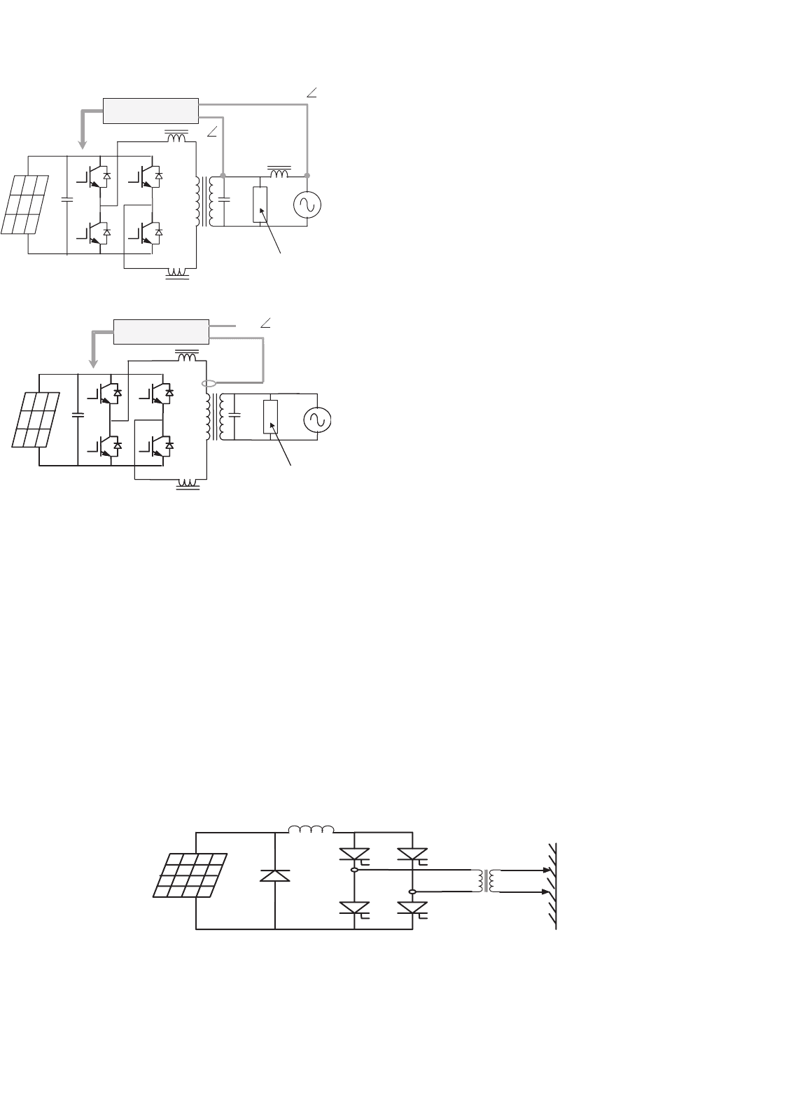
27.2.5.3.3 Inverter with High-frequency Transformer The
50 Hz transformer for a standard PV inverter with PWM
switching scheme can be very heavy and costly. While using
frequencies more than 20 kHz, a ferrite core transformer can
be a better option [3]. A circuit diagram of a grid-connected
PV system using high frequency transformer is shown in the
Fig. 27.35.
The capacitor on the input side of high frequency inverter
acts as the filter. The high frequency inverter with PWM is
used to produce a high frequency AC across the primary wind-
ing of the high frequency transformer. The secondary voltage
of this transformer is rectified using high frequency rectifier.
The DC voltage is interfaced with a thyristor inverter through
low-pass inductor filter and hence connected to the grid. The
line current is required to be sinusoidal and in phase with
the line voltage. To achieve this, the line voltage (V
1
) is mea-
sured to establish the reference waveform for the line current
I
∗
L
. This reference current I
∗
L
multiplied by the transformer
ratio gives the reference current at the output of high fre-
quency inverter. The inverter output can be controlled using
current control technique [40]. These inverters can be with
low frequency transformer isolation or high frequency trans-
former isolation. The low frequency (50/60 Hz) transformer
of a standard inverter with PWM is a very heavy and bulky
component. For residential grid interactive rooftop inverters
below 3 kW rating, high frequency transformer isolation is
often preferred.
27.2.5.3.4 Other PV Inverter Topologies In this section,
some of the inverter topologies discussed in various research
papers have been discussed.
A. Multilevel Converters
Multilevel converters can be used with large PV systems where
multiple PV panels can be configured to create voltage steps.
These multilevel voltage-source converters can synthesize the
AC output terminal voltage from different level of DC voltages
and can produce staircase waveforms. This scheme involves
less complexity, and needs less filtering. One of the schemes
(half-bridge diode-clamped three level inverter [41]) is given
in Fig. 27.36. There is no transformer in this topology. Mul-
tilevel converters can be beneficial for large systems in terms
of cost and efficiency. Problems associated with shading and
malfunction of PV units need to be addressed.
B. Non-insulated Voltage Source
In this scheme [42], string of low voltage PV panels or one
high-voltage unit can be coupled with the grid through DC
to DC converter and voltage-source inverter. This topology is
shown in Fig. 27.37. PWM-switching scheme can be used to
generate AC output. Filter has been used to reject the switching
components.
27 Power Electronics for Renewable Energy Sources 693
Q
1
Q
2
Q
3
Q
4
C
V
c
V
pv1
V
pv2
X
L
Inverter
FIGURE 27.36 Half-bridge diode-clamped three-level inverter.
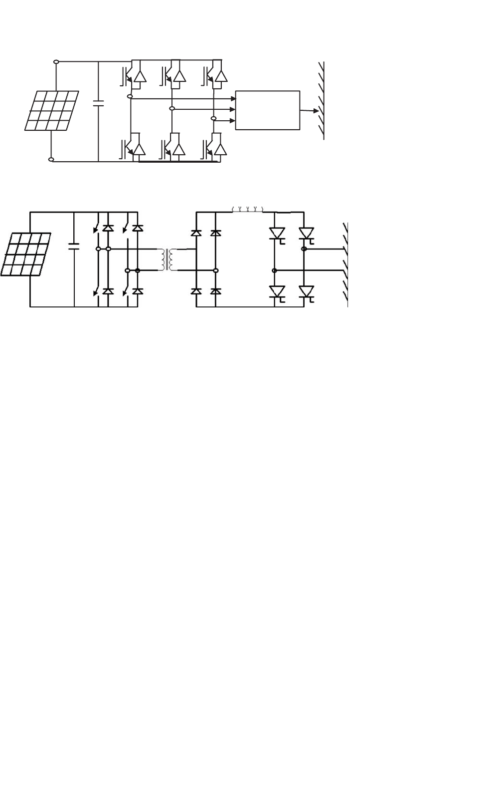
C. Non-insulated Current Source
This type of configuration is shown in Fig. 27.38. Non-
insulated current-source inverters [42] can be used to interface
the PV panels with the grid. This topology involves low cost
which can provide better efficiency. Appropriate controller can
be used to reduce current harmonics.
D. Buck Converter with Half-bridge Transformer Link
PV panels are connected to grid via buck converter and
half bridge as shown in Fig. 27.39. In this, high-frequency
PWM switching has been used at the low-voltage PV side
to generate an attenuated rectified 100 Hz sine-wave current
waveform [43]. Half-wave bridge is utilized to convert this out-
put to 50 Hz signal suitable for grid interconnection. To step
up the voltage, transformer has also been connected before the
grid connection point.
E. Flyback Converter
This converter topology steps up the PV voltage to DC
bus voltage. Pulse width modulation operated converter has
been used for grid connection of PV system (Fig. 27.40).
−
−
−
S
1
S
3
S
2
S
4
V
dc
+
PV panels
+
+
Boost
Chopper
Voltage
Source Inverter
FIGURE 27.37 Non-insulated voltage source.
This scheme is less complex and has less number of switches.
Flyback converters can be beneficial for remote areas due to
less complex power conditioning components.
F. Interface Using Paralleled PV Panels
Low voltage AC bus scheme [44] can be comparatively efficient
and cheaper option. One of the schemes is shown in Fig. 27.41.
A number of smaller PV units can be paralleled together
and then connected to combine single low-frequency trans-
former. In this scheme, the PV panels are connected in parallel
rather than series to avoid problems associated with shading
or malfunction of one of the panels in series connection.
27.2.5.4 Power Control through PV Inverters
The system shown in Fig. 27.42 shows control of power flow on
to the grid [45]. This control can be an analog or a micropro-
cessor system. This control system generates the waveforms
and regulates the waveform amplitude and phase to con-
trol the power flow between the inverter and the grid. The
grid-interfaced PV inverters, voltage-controlled VSI (VCVSI),
or current-controlled VSI (CCVSI) have the potential of bi-
directional power flow. They cannot only feed the local load
but also can export the excess active and reactive power
to the utility grid. An appropriate controller is required in
order to avoid any error in power export due to errors in
synchronization, which can overload the inverter.
There are advantages and limitations associated with each
control mechanism. For instance, VCVSIs provide voltage sup-
port to the load (here the VSI operates as a voltage source),
while CCVSIs provide current support (here the VSI operates
as a current source). The CCVSI is faster in response compared
to the VCVSI, as its power flow is controlled by the switch-
ing instant, whereas in the VCVSI the power flow is controlled
by adjusting the voltage across the decoupling inductor. Active
and reactive power are controlled independently in the CCVSI,
but are coupled in the VCVSI. Generally, the advantages of
one type of VSI are considered as a limitation of the other
type [46].