Power electronic handbook
Подождите немного. Документ загружается.

674 C. V. Nayar et al.
Many wind generators now incorporate speed control mech-
anisms like blade pitch control or use converters/inverters to
regulate power output from variable speed wind turbines. In
Section 27.3, electrical and power conditioning aspects of wind
energy conversion systems were included.
27.2 Power Electronics for Photovoltaic
Power Systems
27.2.1 Basics of Photovoltaics
The density of power radiated from the sun (referred as “solar
energy constant”) at the outer atmosphere is 1.373 kW/m
2
.
Part of this energy is absorbed and scattered by the earth’s
atmosphere. The final incident sunlight on earth’s surface has
a peak density of 1 kW/m
2
at noon in the tropics. The tech-
nology of photovoltaics (PV) is essentially concerned with the
conversion of this energy into usable electrical form. Basic ele-
ment of a PV system is the solar cell. Solar cells can convert
the energy of sunlight directly into electricity. Consumer appli-
ances used to provide services such as lighting, water pumping,
refrigeration, telecommunication, television, etc. can be run
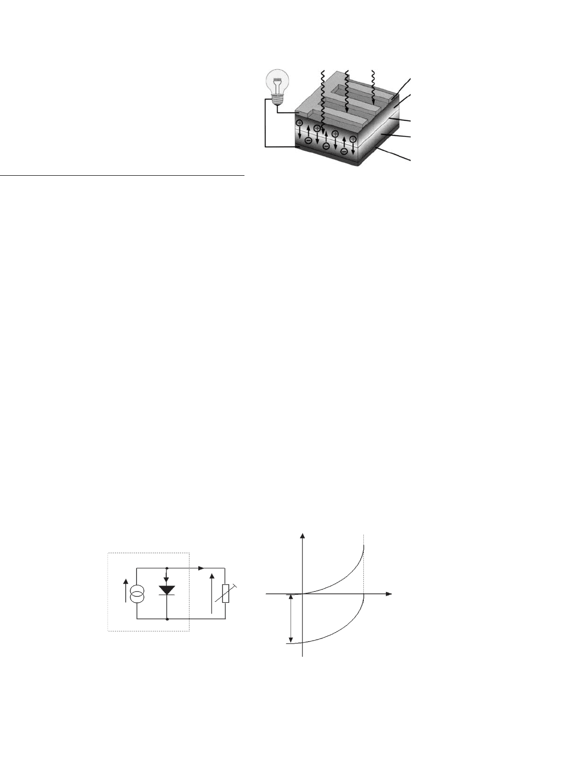
from PV electricity. Solar cells rely on a quantum-mechanical
process known as the “photovoltaic effect” to produce electric-
ity. A typical solar cell consists of a p–n junction formed in a
semiconductor material similar to a diode. Figure 27.1 shows
a schematic diagram of the cross section through a crystalline
solar cell [1]. It consists of a 0.2–0.3 mm thick monocrys-
talline or polycrystalline silicon wafer having two layers with
different electrical properties formed by “doping” it with other
impurities (e.g. boron and phosphorous). An electric field is
established at the junction between the negatively doped (using
phosphorous atoms) and the positively doped (using boron
atoms) silicon layers. If light is incident on the solar cell, the
energy from the light (photons) creates free charge carriers,
which are separated by the electrical field. An electrical volt-
age is generated at the external contacts, so that current can
V
PV CELL
I
ph
I
ph
−I
I
sc
illuminated
eg. solar cell
dark
eg. diode
I
d
I
c
V
c
V
oc
R
(a) (b)
FIGURE 27.2 Simplified equivalent circuit for a solar cell.
light
negative electrode
negative doped silicon
positive doped silicon
PN junction
positive electrode
FIGURE 27.1 Principle of the operation of a solar cell [2].
flow when a load is connected. The photocurrent (I
ph
), which
is internally generated in the solar cell, is proportional to the
radiation intensity.
A simplified equivalent circuit of a solar cell consists of a
current source in parallel with a diode as shown in Fig. 27.2a.
A variable resistor is connected to the solar cell generator
as a load. When the terminals are short-circuited, the out-
put voltage and also the voltage across the diode is zero. The
entire photocurrent (I
ph
) generated by the solar radiation then
flows to the output. The solar cell current has its maximum
(I
sc
). If the load resistance is increased, which results in an
increasing voltage across the p–n junction of the diode, a
portion of the current flows through the diode and the out-
put current decreases by the same amount. When the load
resistor is open-circuited, the output current is zero and the
entire photocurrent flows through the diode. The relation-
ship between current and voltage may be determined from the
diode characteristic equation
I = I
ph
−I
0
(e
qV /kT
−1) = I
ph
−I
d
(27.1)
where q is the electron charge, k is the Boltzmann constant, I
ph
is photocurrent, I
0
is the reverse saturation current, I
d
is diode
current, and T is the solar cell operating temperature (
◦
K). The
current vs voltage (I–V) of a solar cell is thus equivalent to an
“inverted” diode characteristic curve shown in Fig. 27.2b.
27 Power Electronics for Renewable Energy Sources 675
A number of semiconductor materials are suitable for the
manufacturing of solar cells. The most common types using
silicon semiconductor material (Si) are:
• Monocrystalline Si cells.
• Polycrystalline Si cells.
• Amorphous Si cells.
A solar cell can be operated at any point along its char-
acteristic current–voltage curve, as shown in Fig. 27.3. Two
important points on this curve are the open-circuit voltage
(V
oc
) and short-circuit current (I
sc
). The open-circuit voltage
is the maximum voltage at zero current, while short-circuit
current is the maximum current at zero voltage. For a sili-
con solar cell under standard test conditions, V
oc
is typically
0.6–0.7 V, and I
sc
is typically 20–40 mA for every square
centimeter of the cell area. To a good approximation, I
sc
is pro-
portional to the illumination level, whereas V
oc
is proportional
to the logarithm of the illumination level.
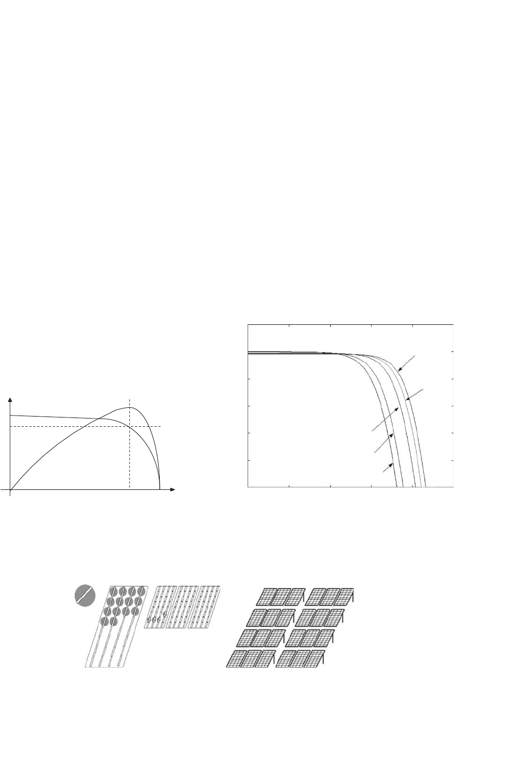
A plot of power (P) against voltage (V ) for this device
(Fig. 27.3) shows that there is a unique point on the I–V curve
at which the solar cell will generate maximum power. This is
known as the maximum power point (V
mp
, I
mp
). To maximize
the power output, steps are usually taken during fabrication,
the three basic cell parameters: open-circuit voltage, short-
circuit current, and fill factor (FF) – a term describing how
V
oc
V
I
sc
I / P
I
mpp
V
mpp
P
mpp
FIGURE 27.3 Current vs voltage (I–V) and current power (P–V)
characteristics for a solar cell.
PV Cell PV Module PV Panel PV Array
FIGURE 27.4 PV generator terms.
“square” the I–V curve is, given by
Fill Factor = (V
mp
×I
mp
)/(V
oc
×I
sc
) (27.2)
For a silicon solar cell, FF is typically 0.6–0.8. Because sili-
con solar cells typically produce only about 0.5 V, a number of
cells are connected in series in a PV module. A panel is a col-
lection of modules physically and electrically grouped together
on a support structure. An array is a collection of panels (see
Fig. 27.4).
The effect of temperature on the performance of sili-
con solar module is illustrated in Fig. 27.5. Note that I
sc
slightly increases linearly with temperature, but, V
oc
and the
maximum power, P
m
decrease with temperature [1].
Figure 27.6 shows the variation of PV current and voltages
at different insolation levels. From Figs. 27.5 and 27.6, it can be
seen that the I–V characteristics of solar cells at a given inso-
lation and temperature consist of a constant voltage segment
BP280 Voltage [V]
0
0
5
Ta=290[K]
Ta=310[K]
Ta=320[K]
Ta=280 [K]
Ta=273 [K]
10 15 20 25
1
2
3
4
5
6
Radiation = 1000 W/m
2
Current [A]
FIGURE 27.5 Effects of temperature on silicon solar cells.
676 C. V. Nayar et al.
0
0
0.5
1.5
2.5
3.5
4.5
1
2
3
4
5
5101520
Ambient Temp. [300 k]
BP280 Voltage [V]
G=200 W/m
2
G=400 W/m
2
G=600 W/m
2
G=800 W/m
2
G=1000 W/m
2
Current [A]
FIGURE 27.6 Typical current/voltage (I–V) characteristic curves for
different insolation.
and a constant current segment [3]. The current is limited,
as the cell is short-circuited. The maximum power condition
occurs at the knee of the characteristic curve where the two
segments meet.
27.2.2 Types of PV Power Systems
Photovoltaic power systems can be classified as:
•
Stand-alone PV systems.
• Hybrid PV systems.
• Grid-connected PV systems.
Stand-alone PV systems, shown in Fig. 27.7, are used in
remote areas with no access to a utility grid. Conventional
power systems used in remote areas often based on man-
ually controlled diesel generators operating continuously or
for a few hours. Extended operation of diesel generators at
PV
Panel
Charge
regulator
unit
+
AC
Load
_
InverterBattery
FIGURE 27.7 Stand-alone PV system.
low load levels significantly increases maintenance costs and
reduces their useful life. Renewable energy sources such as
PV can be added to remote area power systems using diesel
and other fossil fuel powered generators to provide 24-hour
power economically and efficiently. Such systems are called
“hybrid energy systems.” Figure 27.8 shows a schematic of
a PV-diesel hybrid system. In grid-connected PV systems
shown in Fig. 27.9, PV panels are connected to a grid through
inverters without battery storage. These systems can be classi-
fied as small systems like the residential rooftop systems or
large grid-connected systems. The grid-interactive inverters
must be synchronized with the grid in terms of voltage and
frequency.
Diesel
Generator
Power
Conditioning and
Control
Battery
Load
PV Panel
FIGURE 27.8 PV-diesel hybrid system.
Power
Conditioning and
Control
PV Panel
Grid
FIGURE 27.9 Grid-connected PV system.
27 Power Electronics for Renewable Energy Sources 677
27.2.3 Stand-alone PV Systems
The two main stand-alone PV applications are:
• Battery charging.
•
Solar water pumping.
27.2.3.1 Battery Charging
27.2.3.1.1 Batteries for PV Systems Stand-alone PV energy
system requires storage to meet the energy demand dur-
ing periods of low solar irradiation and nighttime. Several
types of batteries are available such as the lead acid, nickel–
cadmium, lithium, zinc bromide, zinc chloride, sodium sulfur,
nickel–hydrogen, redox, and vanadium batteries. The provi-
sion of cost-effective electrical energy storage remains one of
the major challenges for the development of improved PV
power systems. Typically, lead-acid batteries are used to guar-
antee several hours to a few days of energy storage. Their
reasonable cost and general availability has resulted in the
widespread application of lead-acid batteries for remote area
power supplies despite their limited lifetime compared to other
system components. Lead-acid batteries can be deep or shal-
low cycling gelled batteries, batteries with captive or liquid
electrolyte, sealed and non-sealed batteries etc. [4]. Sealed
batteries are valve regulated to permit evolution of excess
hydrogen gas (although catalytic converters are used to con-
vert as much evolved hydrogen and oxygen back to water as
possible). Sealed batteries need less maintenance. The follow-
ing factors are considered in the selection of batteries for PV
applications [1]:
• Deep discharge (70–80% depth of discharge).
• Low charging/discharging current.
• Long duration charge (slow) and discharge (long duty
cycle).
•
Irregular and varying charge/discharge.
• Low self discharge.
• Long life time.
• Less maintenance requirement.
• High energy storage efficiency.
• Low cost.
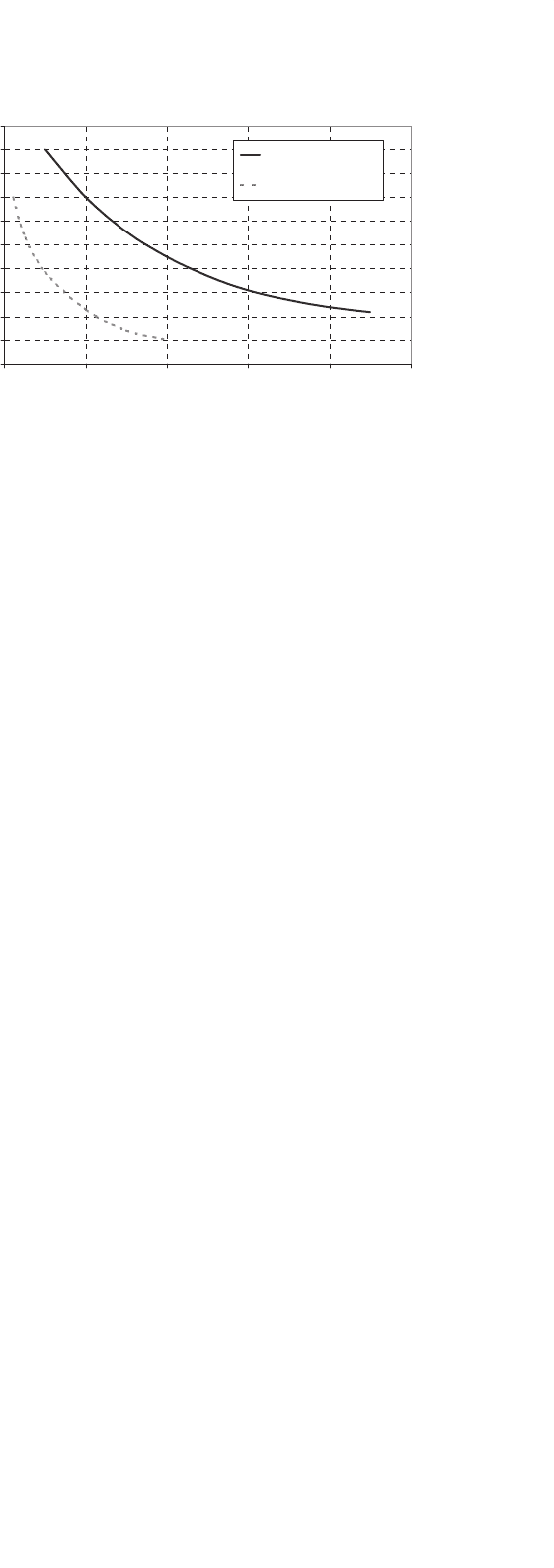
Battery manufacturers specify the nominal number of
complete charge and discharge cycles as a function of the
depth-of-discharge (DOD), as shown in Fig. 27.10. While this
information can be used reliably to predict the lifetime of
lead-acid batteries in conventional applications, such as unin-
terruptable power supplies or electric vehicles, it usually results
in an overestimation of the useful life of the battery bank in
renewable energy systems.
Two of the main factors that have been identified as limit-
ing criteria for the cycle life of batteries in PV power systems
are incomplete charging and prolonged operation at a low
state-of-charge (SOC). The objective of improved battery con-
trol strategies is to extend the lifetime of lead-acid batteries
0
10
20
30
40
50
60
70
80
90
100
0 1000 2000 3000 4000 5000
No of cycles
Depth-of-discharge (%)
Industrial batteries
Automotive batteries
FIGURE 27.10 Nominal number of battery cycles vs DOD.
to achieve a typical number of cycles shown in Fig. 27.10. If
this is achieved, an optimum solution for the required stor-
age capacity and the maximum DOD of the battery can be
found by referring to manufacturer’s information. Increasing
the capacity will reduce the typical DOD and therefore prolong
the battery lifetime. Conversely, it may be more economic to
replace a smaller battery bank more frequently.
27.2.3.1.2 PV Charge Controllers Blocking diodes in series
with PV modules are used to prevent the batteries from being
discharged through the PV cells at night when there is no
sun available to generate energy. These blocking diodes also
protect the battery from short circuits. In a solar power system
consisting of more than one string connected in parallel, if a
short circuit occurs in one of the strings, the blocking diode
prevents the other PV strings to discharge through the short-
circuited string.
The battery storage in a PV system should be properly
controlled to avoid catastrophic operating conditions like
overcharging or frequent deep discharging. Storage batteries
account for most PV system failures and contribute signifi-
cantly to both the initial and the eventual replacement costs.
Charge controllers regulate the charge transfer and prevent the
battery from being excessively charged and discharged. Three
types of charge controllers are commonly used:
• Series charge regulators.
• Shunt charge regulators.
•
DC–DC converters.
A. A Series Charge Regulators
The basic circuit for the series regulators is given in Fig. 27.11.
In the series charge controller, the switch S
1
disconnects the PV
generator when a predefined battery voltage is achieved. When
the voltage reduces below the discharge limit, the load is dis-
connected from the battery to avoid deep discharge beyond
the limit. The main problem associated with this type of con-
troller is the losses associated with the switches. This extra
678 C. V. Nayar et al.
PV
Panel
Charge
Controller
Battery
Load
Switch S
2
Switch S
1
+ _
FIGURE 27.11 Series charge regulator.
power loss has to come from the PV power and this can be
quite significant. Bipolar transistors, metal oxide semi conduc-
tor field effect transistors (MOSFETs), or relays are used as the
switches.
B. Shunt Charge Regulators
In this type, as illustrated in Fig. 27.12, when the battery is fully
charged the PV generator is short-circuited using an electronic
switch (S
1
). Unlike series controllers, this method works more
efficiently even when the battery is completely discharged as
the short-circuit switch need not be activated until the battery
is fully discharged [1].
The blocking diode prevents short-circuiting of the battery.
Shunt-charge regulators are used for the small PV applications
(less than 20 A).
Deep discharge protection is used to protect the battery
against the deep discharge. When the battery voltage reaches
below the minimum set point for deep discharge limit, switch
S
2
disconnects the load. Simple series and shunt regulators
allow only relatively coarse adjustment of the current flow and
seldom meet the exact requirements of PV systems.
PV
Panel
Charge
Controller
Battery +
Load
Switch S
2
Blocking
Diode
_
S
1
FIGURE 27.12 Shunt charge regulator.
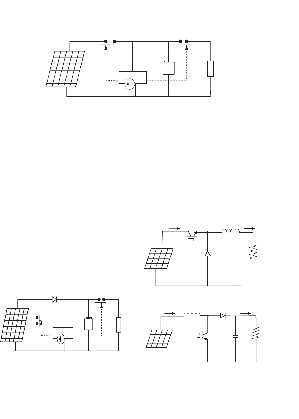
C. DC–DC Converter Type Charge Regulators
Switch mode DC-to-DC converters are used to match the out-
put of a PV generator to a variable load. There are various
types of DC–DC converters such as:
• Buck (step-down) converter.
• Boost (step-up) converter.
• Buck–boost (step-down/up) converter.
Figures 27.13–27.15 show simplified diagrams of these three
basic types converters. The basic concepts are an electronic
switch, an inductor to store energy, and a “flywheel” diode,
which carries the current during that part of switching cycle
V
dc
+
+
D
L
R
I
in
I
out
PV panels
−
−
FIGURE 27.13 Buck converter.
+
C
+
D
L
R
V
dc
PV panels
l
in
l
out
−
−
FIGURE 27.14 Boost converter.
27 Power Electronics for Renewable Energy Sources 679
−
−
V
dc
+
PV panels
+
D
L
in
R
L
out
C
I
t
+
FIGURE 27.15 Boost–buck converter.
when the switch is off. The DC–DC converters allow the charge
current to be reduced continuously in such a way that the
resulting battery voltage is maintained at a specified value.
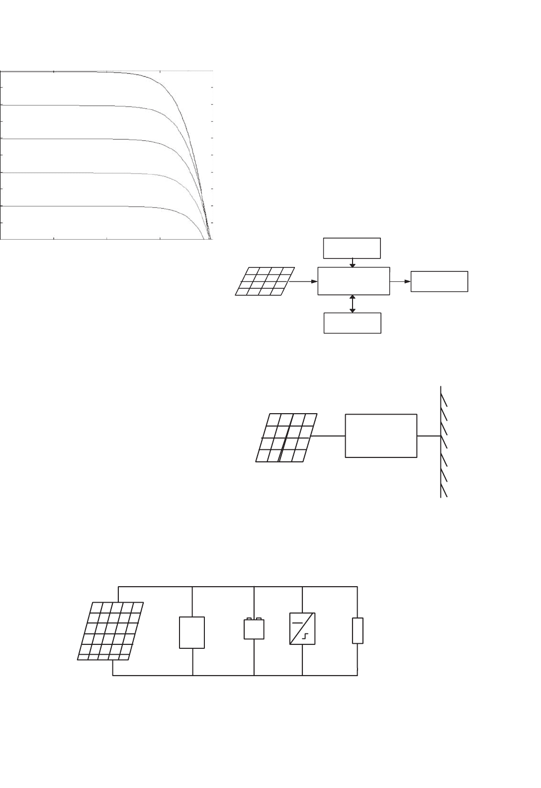
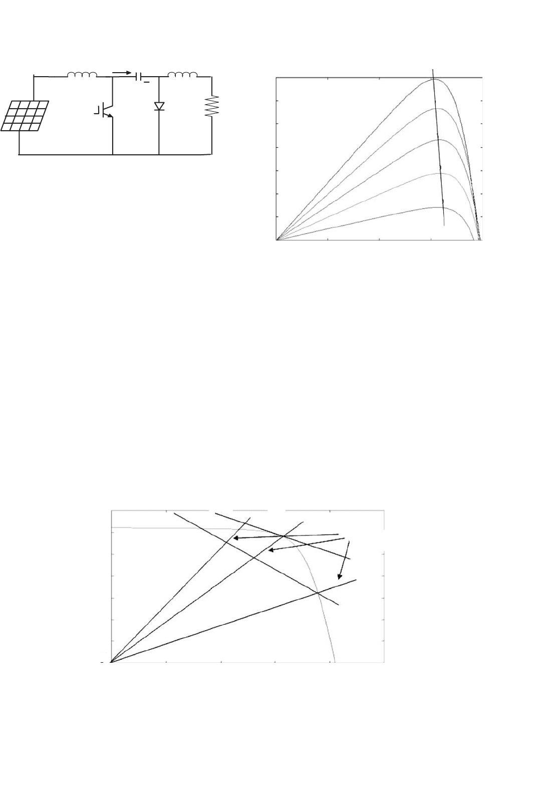
27.2.3.1.3 Maximum Power Point Tracking (MPPT) A
controller that tracks the maximum power point locus of the
PV array is known as the MPPT. In Fig. 27.16, the PV power
output is plotted against the voltage for insolation levels from
200 to 1000 W/m
2
[5]. The points of maximum array power
form a curve termed as the maximum power locus. Due to
high cost of solar cells, it is necessary to operate the PV array
at its maximum power point (MPP). For overall optimal oper-
ation of the system, the load line must match the PV array’s
MPP locus.
Referring to Fig. 27.17, the load characteristics can be either
curve OA or curve OB depending upon the nature of the load
and it’s current and voltage requirements. If load OA is con-
sidered and the load is directly coupled to the solar array,
the array will operate at point A1, delivering only power P1.
The maximum array power available at the given insolation is
P2. In order to use PV array power P2, a power conditioner
coupled between array and the load is needed.
0.5
1.5
2.5
3.5
3
2
1
0 5 10 15
A
A
B
C
Load
P1 P2
Constant Power Points
20 25
Array voltage
Array current
0
FIGURE 27.17 PV array and load characteristics.
0
0
510
10
15 20
20
30
40
50
60
70
BP280 Voltage[V]
Power [W]
Ambient Temp. [300 K]
MPP
G=1000 W/m
2
G=800 W/m
2
G=600 W/m
2
G=400 W/m
2
G=200 W/m
2
FIGURE 27.16 Typical power/voltage characteristics for increased inso-
lation.
There are generally two ways of operating PV modules at
maximum power point. These ways take advantage of analog
and/or digital hardware control to track the MPP of PV arrays.
27.2.3.1.4 Analog Control There are many analog control
mechanisms proposed in different articles. For instance, frac-
tional short-circuit current (I
SC
) [6–9], fractional open-circuit
voltage (V
OP
) [6, 7, 10–13], and ripple correlation control
(RCC) [14–17].
Fractional open-circuit voltage (V
OP
) is one of the simple
analogue control method. It is based on the assumption that
the maximum power point voltage, V
MPP
, is a linear function

680 C. V. Nayar et al.
of the open-circuit voltage, V
OC
. For example V
MPP
= kV
OC
where k ≈ 0.76. This assumption is reasonably accurate even
for large variations in the cell short-circuit current and temper-
ature. This type of MPPT is probably the most common type. A
variation to this method involves periodically open-circuiting
the cell string and measuring the open-circuit voltage. The
appropriate value of V
MPP
can then be obtained with a simple
voltage divider.
27.2.3.1.5 Digital Control There are many digital control
mechanisms that were proposed in different articles. For
instance, perturbation and observation (P&O) or hill climb-
ing [18–23], fuzzy logic [24–28], neural network [18, 29–31],
and incremental conductance (IncCond) [32–35].
The P&O or hill climbing control involves around vary-
ing the input voltage around the optimum value by giving
it a small increment or decrement alternately. The effect on
the output power is then assessed and a further small cor-
rection is made to the input voltage. Therefore, this type of
control is called a hill climbing control. The power output of
the PV array is sampled at an every definite sampling period
and compared with the previous value. In the event, when
power is increased then the solar array voltage is stepped in the
same direction as the previous sample time, but if the power
is reduced then the array voltage is stepped in the opposite
way and try to operate the PV array at its optimum/maximum
power point.
To operate the PV array at the MPP, perturb and adjust
method can be used at regular intervals. Current drawn is sam-
pled every few seconds and the resulting power output of the
solar cells is monitored at regular intervals. When an increased
current results in a higher power, it is further increased until
power output starts to reduce. But if the increased PV current
results in lesser amount of power than in the previous sample,
then the current is reduced until the MPP is reached.
27.2.3.2 Inverters for Stand-alone PV Systems
Inverters convert power from DC to AC while rectifiers con-
vert it from AC to DC. Many inverters are bi-directional, i.e.
they are able to operate in both inverting and rectifying modes.
In many stand-alone PV installations, alternating current is
needed to operate 230 V (or 110 V), 50 Hz (or 60 Hz) appli-
ances. Generally stand-alone inverters operate at 12, 24, 48, 96,
120, or 240 V DC depending upon the power level. Ideally, an
inverter for a stand-alone PV system should have the following
features:
• Sinusoidal output voltage.
• Voltage and frequency within the allowable limits.
• Cable to handle large variation in input voltage.
• Output voltage regulation.
• High efficiency at light loads.
• Less harmonic generation by the inverter to avoid damage
to electronic appliances like television, additional losses,
and heating of appliances.
• Photovoltaic inverters must be able to withstand over-
loading for short term to take care of higher starting
currents from pumps, refrigerators, etc.
• Adequate protection arrangement for over/under-voltage
and frequency, short circuit etc.
• Surge capacity.
•
Low idling and no load losses.
• Low battery voltage disconnect.
• Low audio and radio frequency (RF) noise.
Several different semiconductor devices such as metal oxide
semiconductor field effect transistor (MOSFETs) and insu-
lated gate bipolar transistors (IGBTs) are used in the power
stage of inverters. Typically MOSFETs are used in units up to
5 kVA and 96 V DC. They have the advantage of low switch-
ing losses at higher frequencies. Because the on-state voltage
drop is 2 V DC, IGBTs are generally used only above 96 V DC
systems.
Voltage source inverters are usually used in stand-alone
applications. They can be single phase or three phase. There
are three switching techniques commonly used: square wave,
quasi-square wave, and pulse width modulation. Square-wave
or modified square-wave inverters can supply power tools,
resistive heaters, or incandescent lights, which do not require
a high quality sine wave for reliable and efficient operation.
However, many household appliances require low distortion
sinusoidal waveforms. The use of true sine-wave inverters is
recommended for remote area power systems. Pulse width
modulated (PWM) switching is generally used for obtaining
sinusoidal output from the inverters.
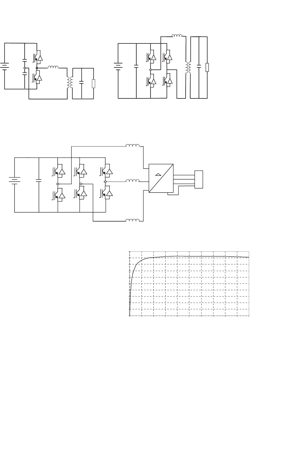
A general layout of a single-phase system, both half bridge
and full bridge, is shown in Fig. 27.18. In Fig. 27.18a, single-
phase half bridge is with two switches, S
1
and S
2
, the capacitors
C
1
and C
2
are connected in series across the DC source.
The junction between the capacitors is at the mid-potential.
Voltage across each capacitor is V
dc
/2. Switches S
1
and S
2
can
be switched on/off periodically to produce AC voltage. Filter
(L
f
and C
f
) is used to reduce high-switch frequency compo-
nents and to produce sinusoidal output from the inverter. The
output of inverter is connected to load through a transformer.
Figure 27.18b shows the similar arrangement for full-bridge
configuration with four switches. For the same input source
voltage, the full-bridge output is twice and the switches carry
less current for the same load power.
The power circuit of a three phase four-wire inverter is
shown in Fig. 27.19. The output of the inverter is connected to
load via three-phase transformer (delta/Y). The star point of
the transformer secondary gives the neutral connection. Three
phase or single phase can be connected to this system. Alter-
natively, a center tap DC source can be used to supply the
converter and the mid-point can be used as the neutral.
27 Power Electronics for Renewable Energy Sources 681
+
−−
+
Transformer Load
Transformer Load
S
1
S
2
V
dc
C
1
C
2
S
1
S
2
V
dc
C
1
L
f
S
3
S
4
C
f
C
f
L
f
(a) (b)
FIGURE 27.18 Single-phase inverter: (a) half bridge and (b) full bridge.
S
1
S
2
V
dc
+
−
C
1
Load
3 Phase
Transformer
S
3
S
4
S
5
S
6
Y
Filter
Tx.
Line
FIGURE 27.19 A stand-alone three-phase four wire inverter.
Figure 27.20 shows the inverter efficiency for a typical
inverter used in remote area power systems. It is important to
consider that the system load is typically well below the nom-
inal inverter capacity P
nom
, which results in low conversion
efficiencies at loads below 10% of the rated inverter output
power. Optimum overall system operation is achieved if the
total energy dissipated in the inverter is minimized. The high
conversion efficiency at low power levels of recently developed
inverters for grid-connected PV systems shows that there is a
significant potential for further improvements in efficiency.
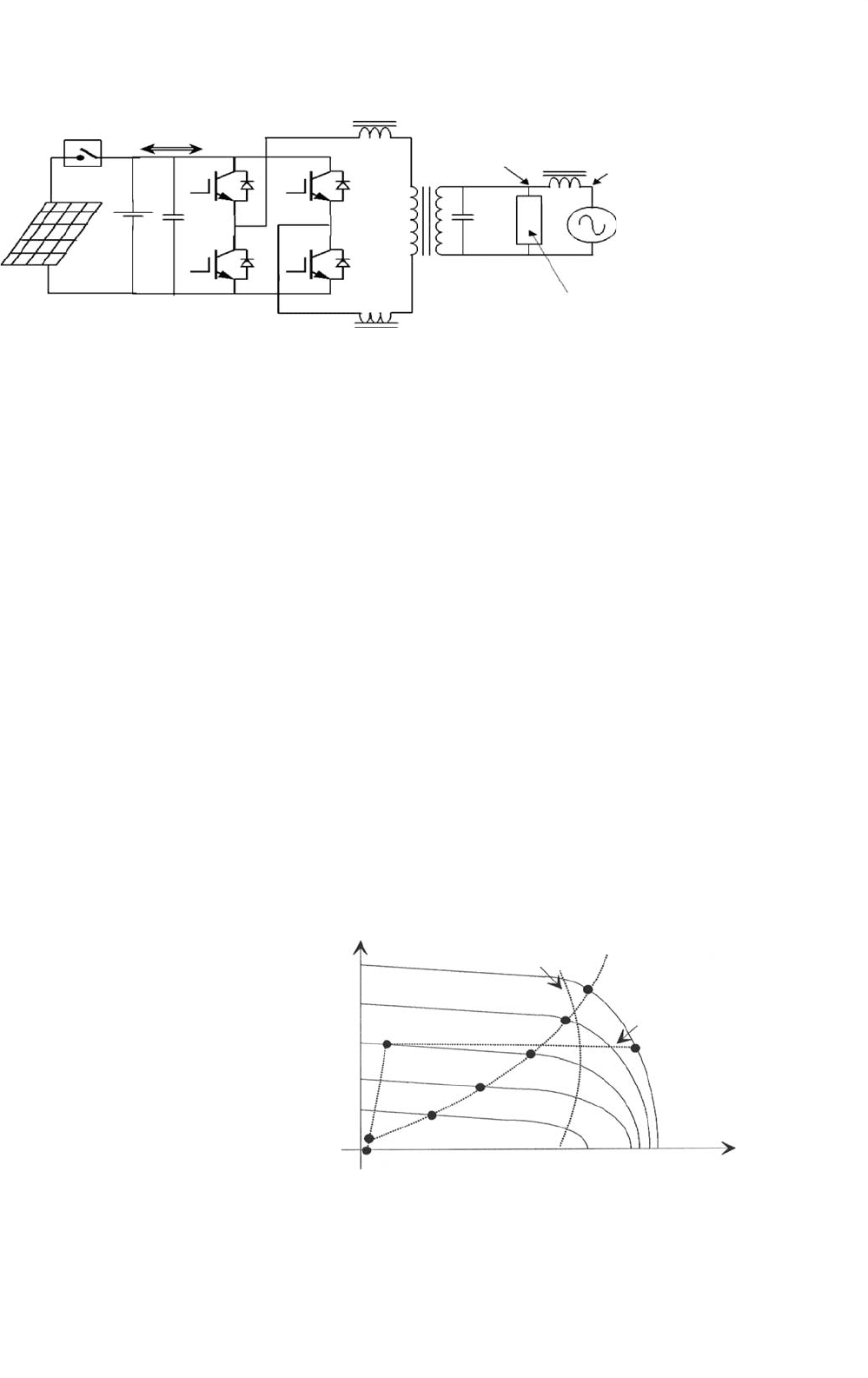
Bi-directional inverters convert DC power to AC power
(inverter) or AC power to DC power (rectifier) and are becom-
ing very popular in remote area power systems [4, 5]. The
principle of a stand-alone single-phase bi-directional inverter
used in a PV/battery/diesel hybrid system can be explained by
referring Fig. 27.21. A charge controller is used to interface
the PV array and the battery. The inverter has a full-bridge
configuration realized using four power electronic switches
(MOSFET or IGBTs) S
1
–S
4
. In this scheme, the diagonally
opposite switches (S
1
,S
4
) and (S
2
,S
3
) are switched using a
sinusoidally PWM gate pulses. The inverter produces sinu-
soidal output voltage. The inductors X
1
, X
2
, and the AC output
capacitor C
2
filter out the high-switch frequency components
0
10
20
30
40
50
60
70
80
90
100
0 0.2 0.3 0.4 0.5 0.6 0.7 0.8 0.9 1
P
inv
/ P
nom
Efficiency (%)
0.1
FIGURE 27.20 Typical inverter efficiency curve.
from the output waveform. Most inverter topologies use a low
frequency (50 or 60 Hz) transformer to step up the inverter
output voltage. In this scheme, the diesel generator and the
converter are connected in parallel to supply the load. The
voltage sources, diesel and inverter, are separated by the link
inductor X
m
. The bi-directional power flow between inverter
and the diesel generator can be established.
682 C. V. Nayar et al.
Charge
Controller
PV panels
Battery
Power flow
Converter
voltage V
c
Transformer
Diesel
voltage V
g
Load
Inductor
X
g
Q
1
Q
3
Q
4
Q
2
C
1
C
2
X
1
X
2
FIGURE 27.21 Bi-directional inverter system.
The power flow through the link inductor, X
m
,is
S
m
= V
m
I
∗
m
(27.3)
P
m
= (V
m
V
c
sin δ)/X
m
(27.4)
Q
m
= (V
m
/X
m
)(V
m
−V
c
cos δ) (27.5)
δ = sin
−1
[(X
m
P
m
)/(V
m
V
c
)] (27.6)
where δ is the phase angle between the two voltages. From
Eq. (27.4), it can be seen that the power supplied by
the inverter from the batteries (inverter mode) or supplied
to the batteries (charging mode) can be controlled by control-
ling the phase angle δ. The PWM pulses separately control the
amplitude of the converter voltage, V
c
, while the phase angle
with respect to the diesel voltage is varied for power flow.
27.2.3.3 Solar Water Pumping
In many remote and rural areas, hand pumps or diesel driven
pumps are used for water supply. Diesel pumps consume fossil
fuel, affects environment, needs more maintenance, and are
less reliable. Photovoltaic powered water pumps have received
considerable attention recently due to major developments in
the field of solar cell materials and power electronic systems
technology.
27.2.3.3.1 Types of Pumps Two types of pumps are com-
monly used for the water pumping applications: positive and
centrifugal displacement. Both centrifugal and positive dis-
placement pumps can be further classified into those with
motors that are (a) surface mounted and those which are
(b) submerged into the water (“submersible”).
Displacement pumps have water output directly propor-
tional to the speed of the pump, but, almost independent of
head. These pumps are used for solar water pumping from
deep wells or bores. They may be piston type pumps, or use
diaphragm driven by a cam, rotary screw type, or use progres-
sive cavity system. The pumping rate of these pumps is directly
related to the speed and hence constant torque is desired.
Centrifugal pumps are used for low-head applications espe-
cially if they are directly interfaced with the solar panels.
Centrifugal pumps are designed for fixed-head applications
and the pressure difference generated increases in relation to
the speed of pump. These pumps are rotating impeller type,
which throws the water radially against a casing, so shaped that
the momentum of the water is converted into useful pressure
for lifting [4]. The centrifugal pumps have relatively high effi-
ciency but it reduces at lower speeds, which can be a problem
for the solar water pumping system at the time of low light
levels. The single-stage centrifugal pump has just one impeller
whereas most borehole pumps are multistage types where the
outlet from one impeller goes into the center of another and
each one keeps increasing the pressure difference.
From Fig. 27.22, it is quite obvious that the load line is
located relatively faraway from P
max
line. It has been reported
that the daily utilization efficiency for a DC motor drive is
87% for a centrifugal pump compared to 57% for a con-
stant torque characteristics load. Hence, centrifugal pumps are
more compatible with PV arrays. The system operating point
Voltage (V)
100% Insolation
(a)
(b)
h
a
b
c
d
P
max
e
f
g
80%
40%
Current (A)
FIGURE 27.22 I–V characteristics of a PV array and two mechanical
loads: (a) constant torque and (b) centrifugal pump.
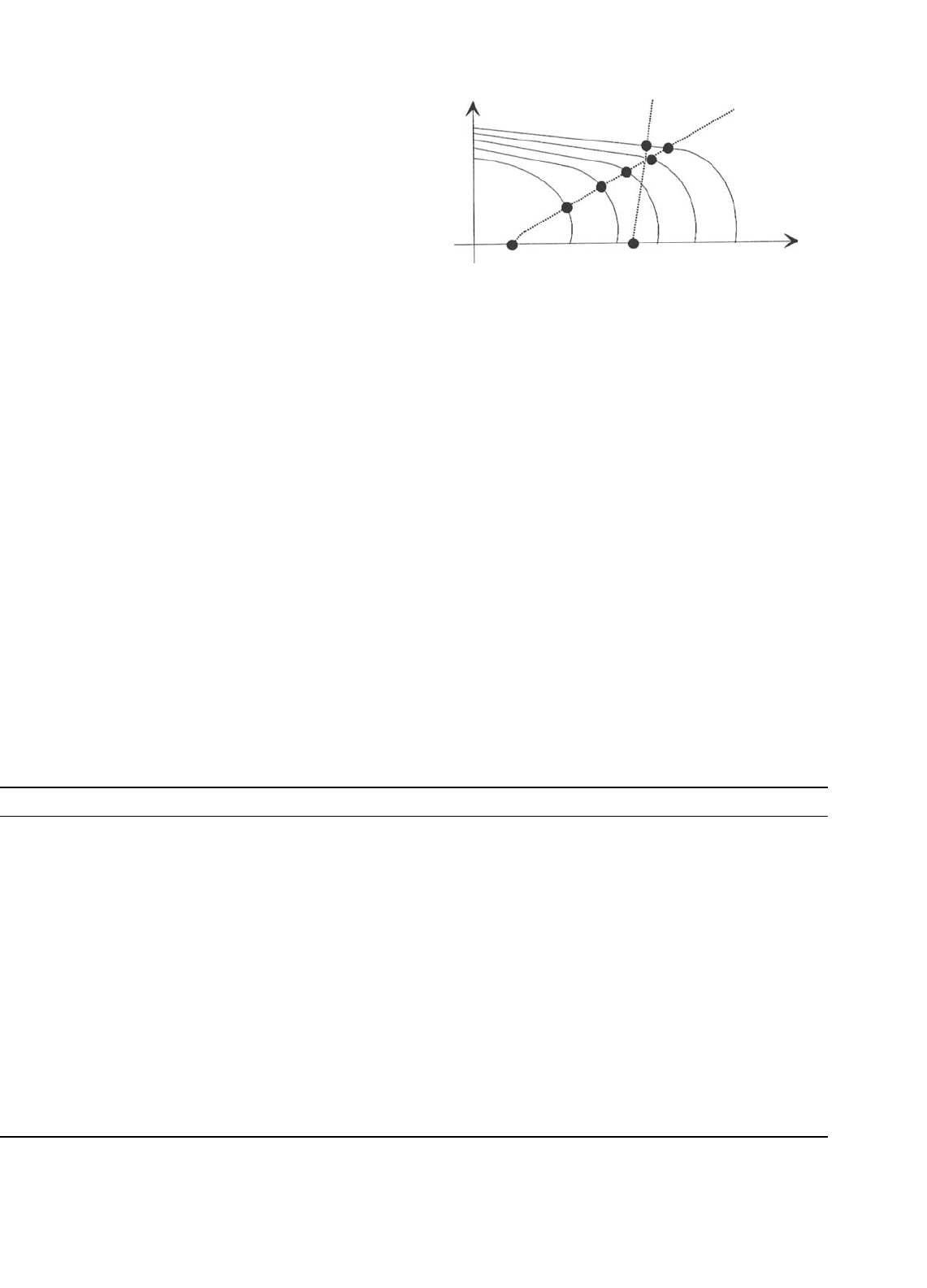
27 Power Electronics for Renewable Energy Sources 683
is determined by the intersection of the I–V characteristics of
the PV array and the motor as shown in Fig. 27.22. The torque-
speed slope is normally large due to the armature resistance
being small. At the instant of starting, the speed and the back
emf are zero. Hence the motor starting current is approxi-
mately the short-circuit current of the PV array. By matching
the load to the PV source through MPPT, the starting torque
increases.
The matching of a DC motor depends upon the type of
load being used. For instance, a centrifugal pump is charac-
terized by having the load torque proportional to the square
of speed. The operating characteristics of the system (i.e. PV
source, permanent magnet (PM) DC motor and load) are at
the intersection of the motor and load characteristics as shown
in Fig. 27.23 (i.e. points a, b, c, d, e, and f for centrifugal pump).
From Fig. 27.23, the system utilizing the centrifugal pump as
its load tends to start at low solar irradiation (point a) level.
However, for the systems with an almost constant torque char-
acteristics in Fig. 27.22, the start is at almost 50% of one sun
(full insolation) which results in short period of operation.
27.2.3.3.2 Types of Motors There are various types of
motors available for the PV water pumping applications:
• DC motors.
• AC motors.
DC motors are preferred where direct coupling to PV panels
is desired whereas AC motors are coupled to the solar panels
through inverters. AC motors in general are cheaper than the
DC motors and are more reliable but the DC motors are more
TABLE 27.1 Comparison of the different types of motor used for PV water pumping
Types of motor Advantages Disadvantages Main features
Brushed DC Simple and efficient for PV applications. Brushes need to be replaced periodically
(typical replacement interval is
2000–4000 hr or 2 years).
Requires MPPT for optimum performance.
No complex control circuits is required as
the motor starts without high current
surge.
Available only in small motor sizes.
Increasing current (by paralleling PV
modules) increases the torque.
These motors will run slowly but do not
overheat with reduced voltage.
Increasing voltage (by series PV modules)
increases the speed.
Brush-less DC Efficient.
Less maintenance is required.
Electronic computation adds to extra cost,
complexity, and increased risk of
failure/malfunction.
Growing trend among PV pump
manufacturers to use brush-less DC
motors, primarily for centrifugal type
submersible pumps.In most cases, oil cooled, can’t be
submerged as deep as water cooled AC
units.
AC induction
motors
No brushes to replace. Needs an inverter to convert DC output
from PV to AC adding additional cost
and complexity.
Available for single or three supply.
Can use existing AC motor/pump technology
which is cheaper and easily available
worldwide. These motors can handle larger
pumping requirements.
Inverters are designed to regulate frequency
to maximize power to the motor in
response to changing insolation levels.
Less efficient than DC motor-pump units.
Prone to overheating if current is not
adequate to start the motor or if the
voltage is too low.
(a) (b)
a
g
b
c
d
e
h
f
20%
60%
80%
Speed (rad/sec)
Torque (Nm)
100% Insolation
FIGURE 27.23 Speed torque characteristics of a DC motor and two
mechanical loads: (a) helical rotor and (b) centrifugal pump.
efficient. The DC motors used for solar pumping applications
are:
• Permanent magnet DC motors with brushes.
• Permanent DC magnet motors without brushes.
In DC motors with the brushes, the brushes are used to
deliver power to the commutator and need frequent replace-
ment due to wear and tear. These motors are not suitable
for submersible applications unless long transmission shafts
are used. Brush-less DC permanent magnet motors have been
developed for submersible applications.
The AC motors are of the induction motor type, which is
cheaper than DC motors and available, worldwide. However,
they need inverters to change DC input from PV to AC power.
A comparison of the different types of motors used for PV
water pumping is given in Table 27.1.