Power electronic handbook
Подождите немного. Документ загружается.

25 Automotive Applications of Power Electronics 643
12 V
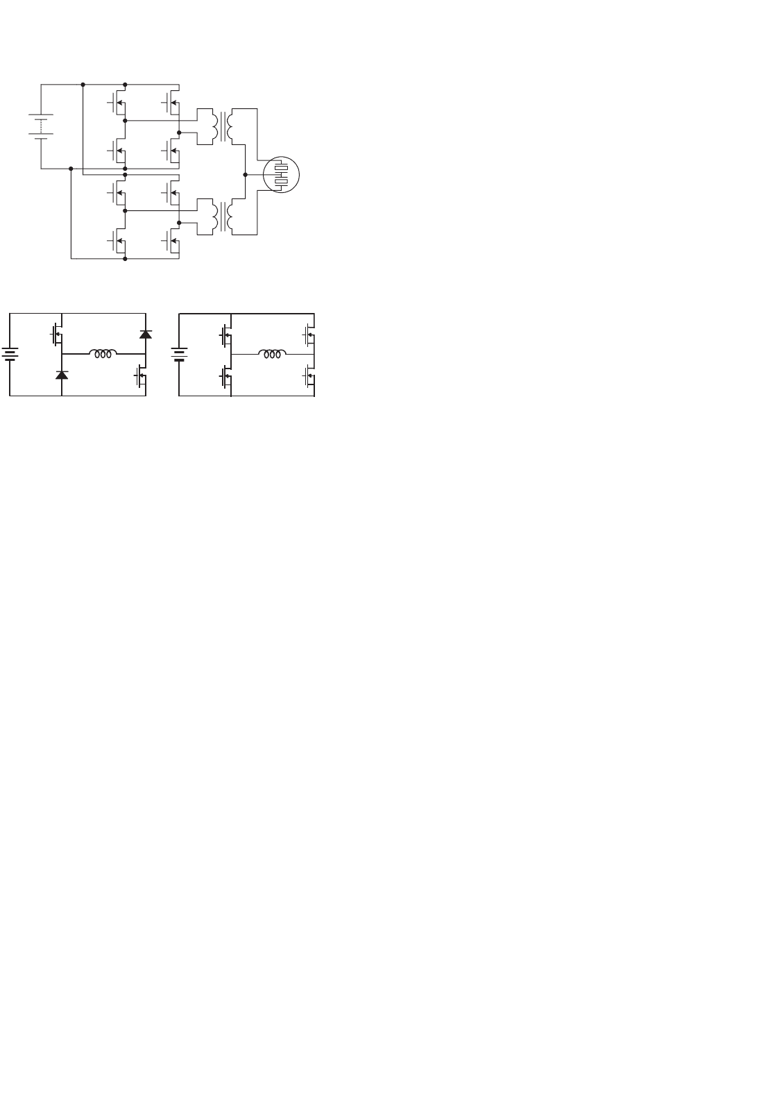
Ultrasonic
Motor
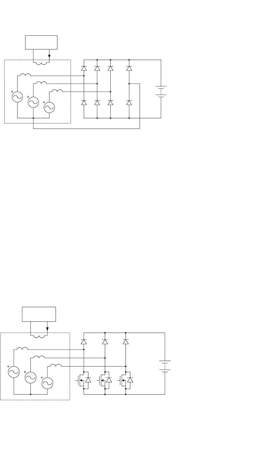
FIGURE 25.7 Drive circuit for an ultrasonic motor.
Solenoid
Coil
Solenoid
Coil
(a) (b)
FIGURE 25.8 Power electronic circuits for driving solenoids.
by electromechanically driven engine valves [25]. The opening
and closing of the intake and exhaust valves can be controlled
to achieve optimum engine performance and improved fuel
economy over a wide range of conditions determined by vari-
ables such as the speed, load, altitude, and temperature. The
present cam system provides a valve profile that can give opti-
mum engine performance and improved fuel economy only
under certain conditions.
Two power electronic circuits suitable for driving the
solenoids for valve actuation are shown in Fig. 25.8. The
circuit of Fig. 25.8a is suitable for solenoids that require uni-
directional currents through their coils, while the circuit of
Fig. 25.8b is suitable for solenoids that require bidirectional
currents through their coils.
25.4.5 Electric Air Conditioner
It is desirable to replace some of the engine-driven functions
of a vehicle with electrically driven counterparts. The benefits
of driving these functions electrically include the elimina-
tion of belts and pulleys, improved design and control due
to independence from engine speed, and resulting increased
efficiency and improved fuel economy. Furthermore, there is
the opportunity for operation of the function in the engine-off
condition.
The air conditioner is an example of an engine-driven func-
tion that could benefit from electrification. The engine drives
the compressor of the air conditioner. Consequently, the speed
of the compressor varies over a wide range and the compres-
sor has to be over-sized to provide the desired performance at
engine idle. Also, since the compressor speed is dependent on
the engine speed, excessive cooling occurs at highway speeds
requiring the cool air to be blended with the hot air to keep
the temperature at the desired level. Furthermore, shaft seals
and rubber hoses can lead to the loss of refrigerant (CFC) and
pose an environmental challenge.
In an electric air conditioner, an electric motor is used to
drive the compressor [26]. The motor is usually a three-phase
brushless dc motor driven by a three-phase MOSFET bridge.
The speed of the compressor in an electric air conditioner is
independent of the engine speed. As a result, the compres-
sor does not have to be over-sized and excessive cooling does
not occur. Also, shaft seals and hoses can be replaced with a
hermetically sealed system. Another benefit of an electric air
conditioner is the flexibility in its location, since it does not
have to be driven by the engine.
25.4.6 Electric and Electrohydraulic Power
Steering Systems
The hydraulic power steering system of a vehicle is another
example of an engine-driven accessory. This system can be
replaced with an electric power steering (EPS) system in which
a brushless dc motor is used to provide the steering power
assist [27]. The electric power steering system is more effi-
cient than the hydraulic power steering system because, unlike
the engine-driven hydraulic steering pump, which is driven by
the engine all the time, the motor operates only on demand.
Another system that can replace the hydraulic power steering
system is the electrohydraulic power steering (EHPS) system.
In this case, a brushless dc motor and inverter can be employed
to drive the hydraulic steering pump. The ability of the EPHS
system to drive the pump only on demand leads to energy
savings of as much as 80% as compared with the conven-
tional hydraulic system. Challenges in implementing EPS and
EPHS systems include meeting the required levels of cost and
reliability for this critical vehicle subsystem.
25.4.7 Motor Speed Control
Some of the motors used in a vehicle require variable speed
control. Consider, as an example, the blower motor used to
provide air flow to the passenger compartment. This motor is
typically a permanent magnet dc motor with a squirrel-cage
fan. The speed of the motor is usually controlled by varying
the resistance connected in series with the motor winding.
This method of speed control leads to a significant power
loss. A low-loss method of speed control employs semicon-
ductor devices as shown in Fig. 25.9. In this case, the speed
of the motor is controlled via PWM – that is, by switching
the MOSFET on and off with different duty-ratios for differ-
ent speed settings. An input filter is needed to reduce the EMI
generated by the switching of the MOSFET. This method of
speed control is equivalent to supplying power to the motor
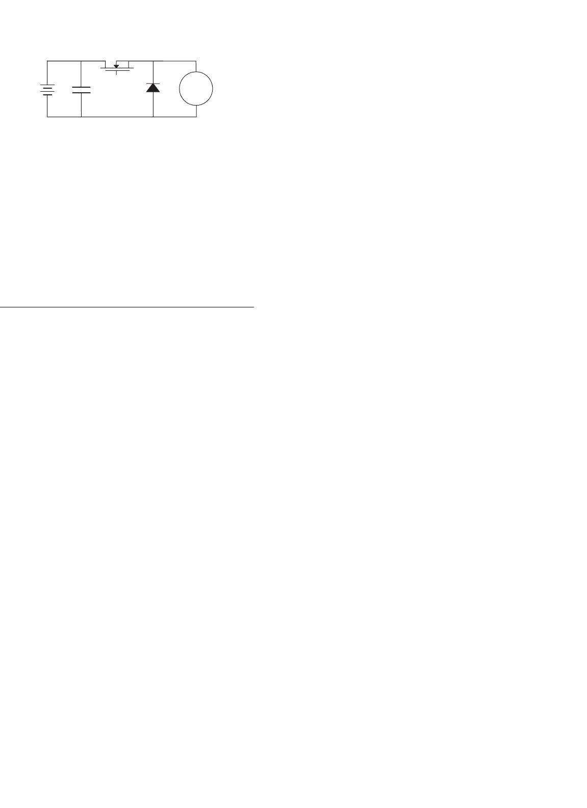
644 D. J. Perreault et al.
Motor
FIGURE 25.9 Low-loss circuit to control the speed of a motor.
through a variable-output dc-to-dc converter. The converter
is located close to the motor and no filter is required between
the converter output and motor winding.
Another low-loss method that can be used to control the
speed of a motor employs a three-phase brushless dc motor.
The speed in this case is controlled by controlling the MOS-
FETs in the dc-to-three-phase-ac converter that drives the
motor.
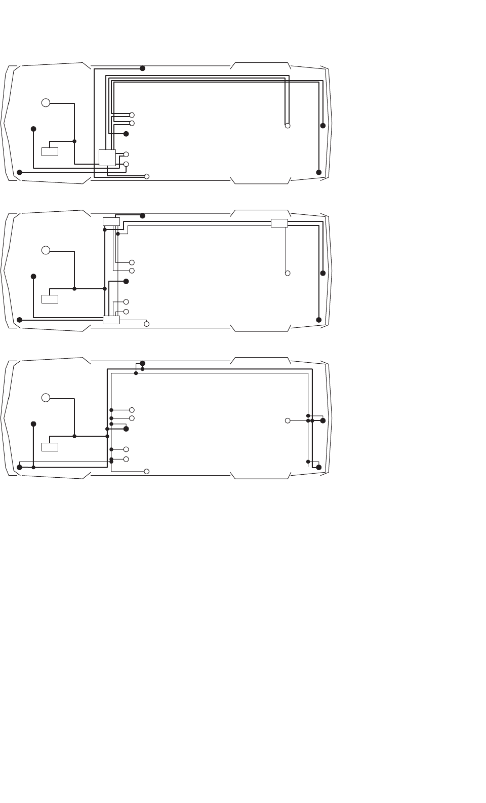
25.5 Multiplexed Load Control
Another emerging application of power electronics in auto-
mobiles is in the area of load control. In the conventional
point-to-point wiring architecture, most of the loads are con-
trolled directly by the primary mechanical switches, as shown
in Fig. 25.1. In a point-to-point wiring architecture, each load
has a dedicated wire connecting it to the fuse box via the
primary switch. Consequently, fairly heavy wires have to be
routed all over the vehicle, as illustrated in Fig. 25.10a. The
situation is made worse when multiple switches control the
same load, as is the case with power windows and power
door locks. The complete harness of a 1994 C-class Mercedes-
Benz that uses point-to-point wiring has about 1000 wires,
with a total length of 2 km, over 300 connectors and weighs
36 kg. The process of assembling the wiring harness is difficult
and time consuming, leading to high labor costs. Retrofitting,
fault tracing, and repairing are time consuming and expen-
sive. The bulky harness also places constraints on the vehicle
body design, and the large number of connectors compromise
system reliability.
An alternative wiring technique is to control the loads
remotely and multiplex the control signals over a communi-
cation bus, as shown in Fig. 25.10b and c. A control message is
sent on the communication bus to switch a particular load on
or off. This allows more flexibility in the layout of the power
cables and could allow the pre-assembly of the harness to be
more automated. Furthermore, with communication between
the remote switches, it is practical to have a power manage-
ment system than can turn off non-essential loads when there
is a power shortage. One possibility is to group the remote
switches into strategically located distribution boxes, as shown
in Fig. 25.10b. A power and a communication bus connect
the distribution boxes. Another possibility is to integrate the
remote switches with the load, i.e. point-of-load switching,
as shown in Fig. 25.10c. In Fig. 25.10b the transceivers are
also built into the distribution boxes, while in Fig. 25.10c each
load and primary switch has an integrated transceiver. The
point-of-load switching topology is attractive because of its
simplicity, but raises cost and fusing challenges.
Multiplexed remote switching architectures have been
under consideration since at least the early 1970s, when
Ziomek investigated their application to various electrical sub-
systems [28]. The initial interest was dampened by cost and
reliability concerns and the non-availability of appropriate
remote switches. However, advances in semiconductor tech-
nology and rapid growth in the automotive electrical system
revived interest in multiplexed architectures. The SAE Mul-
tiplexing Standards Committee has partitioned automotive
communications into three classes: Class A for low data-rate
(1–10 kbit/s) communication for the control of body func-
tions, such as headlamps, windshield wipers, and power win-
dows, Class B for medium data-rate (10–100 kbit/s) parametric
data exchange, and Class C for high data-rate (1 Mbit/s) real-
time communication between safety critical functions, such
as between ABS sensors and brake actuators [29]. Although
load control is categorized as Class A, lack of any widely
accepted Class A communication protocols has lead to the
application of Class B and Class C communication IC’s to
load control. Class B has received the most attention due to
the California Air Resources Board mandated requirement for
on-board diagnostics (OBD II) and a large number of com-
peting protocols, including the French vehicle-area network
(VAN), the ISO 9141 and the SAE J1850, have been devel-
oped [30]. Of these, the SAE J1850 is the most popular in
the US. Another popular protocol is the controller area net-
work (CAN) developed by Bosch [31]. Although designed for
Class C with bit rates up to 1 Mbit/s, it is being applied for
Class A and Class B applications due to the availability of
inexpensive CAN ICs from a large number of semiconductor
manufacturers.
Remote switching systems require remote power switches.
An ideal remote switch must have a low on-state voltage,
be easy to drive from a micro-controller, and incorporate
current sensing. A low on-state voltage helps minimize the
heatsinking requirements, while current sensing is needed for
the circuit protection function to be incorporated into the
switch. To withstand the harsh automotive environment the
switch must also be rugged. Furthermore, if PWM control is
required for the load, the switch must have short turn-on and
turn-off times and a high cycle-life. The traditional means of
remotely switching loads in an automobile is via electrome-
chanical relays. Although relays offer the lowest voltage drop
per unit cost, they require large drive current, are relatively
large, are difficult to integrate with logic, and are not suit-
able for PWM applications [32–34]. Therefore, their use will
be limited to very high current, non-PWM applications. The
power levels of the individual loads in the automobile are too
low for IGBTs and MCTs to be competitive. Bipolar transistors
25 Automotive Applications of Power Electronics 645
F1
S4
S1
S2
S5
S6
S3
L2
L1
L4
L3
L6
L5
(a)
(b)
Alternator
Battery
S4
S1
S2
S5
S6
S3
L2
L1
L4
L3
L6
L5
(c)
Communication Bus
Communication Bus
Power Bus
Alternator
Battery
Alternator
Battery
S4
S1
S2
S5
S6
S3
L2
L1
L4
L3
L6
L5
Power Bus
D2
D1
D2
FIGURE 25.10 Alternative control strategies illustrated for a simple automotive electrical system with six loads (L1-6) and six primary switches
(S1-6): (a) conventional direct switching architecture with a single fusebox (F1); (b) multiplexed remote switching architecture, with remote switches
and transceivers in three distribution boxes (D1-3); and (c) multiplexed point-of-load switching with electronics integrated into the loads and the
primary switches.
are also not very attractive because they are harder to drive
than a MOS-gated device. Because of its fast switching speed,
low voltage drop, relative immunity to thermal runaway, low
drive requirements, and ease of integration with logic, the
power MOSFET is the most attractive candidate for remote
switching. Smart-power MOSFET devices with integrated logic
interface and circuit protection have recently become available.
Use of these devices for power electronic control of individual
loads has become economically competitive in some subsys-
tems, and may be expected to become more so with the advent
of higher voltage electrical systems.
The benefits of remote switching electrical distribution sys-
tems have been demonstrated by Furuichi et al. [35]. The
multiplexed architecture they implemented had 10 remote
units (two power units with fuses, power drivers and signal
inputs, five load control units with power drivers and signal
inputs but no fuses, and three signal input units with only sig-
nal inputs). To increase system reliability, each power unit was
connected to the battery via independently fused power cables.
Although wiring cost decreased, the authors report an increase
in overall system cost due to the additional cost of the remote
units. Intel’s CAN ICs with data rates of 20 kbit/s were used
646 D. J. Perreault et al.
TABLE 25.5 Comparison of a multiplexed and the conventional
system, as reported by Furuichi et al. for a compact vehicle [35].
In the multiplexed system, the function of nine electronic control
units (ECUs) was integrated into the remote units
Point-to-point Multiplexed Change (%)
Harness weight (kg) 14.0 9.8 −30
ECU weight (kg) 1.2 0.0 N/A
Remote unit weight (kg) 0.0 3.5 N/A
Total weight (kg) 15.2 13.3 −12.5
Number of wires 743 580 −21.9
Number of terminals 1195 915 −23.4
Number of splices 295 246 −16.6
Length of wire (m) 809 619 −23.5
for the transmission and reception of control signals over an
unshielded twisted-pair ring bus. Intelligent power MOSFETs
were used as the remote switches and fusing was done with
mini-fuses. The results of their work are shown in Table 25.5.
Although weight of the wiring harness was reduced by 30%,
the total system weight decreased by only 12.5% due to the
added weight of the remote units.
25.6 Electromechanical Power
Conversion
Power is generated in the automobile by an electrical machine
driven by the engine. In the early days of the automobile,
the electrical load was small and a dc generator was used for
this purpose. As the electrical loads grew, the dc generator
could not meet the growing demand of electrical power and
was displaced by a three-phase alternator and diode rectifier.
Continuously increasing power and performance require-
ments are driving further evolution in automotive power
generation and control, and are motivating the introduction of
power electronics and improved electrical machines in auto-
mobiles. In addition to high-power alternators, future appli-
cations of electromechanical power conversion may include
integrated starter/alternators and propulsion systems. This
section describes some of the machine and power elec-
tronic technologies that are useful for meeting the increasing
challenges in the automobile.
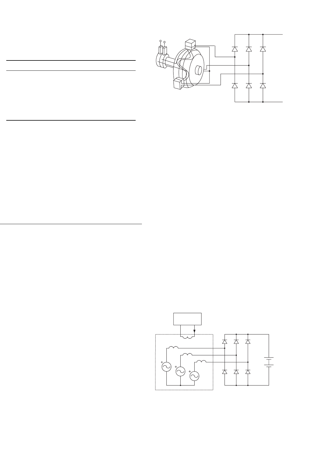
25.6.1 The Lundell Alternator
The Lundell, or claw-pole, alternator is a three-phase wound-
field synchronous machine that is almost universally used for
power generation in present-day vehicles [1]. As illustrated in
Fig. 25.11, the rotor is made of a pair of stamped pole pieces
(“claw poles”) fixed around a cylindrical field coil. The field
winding is driven from the stator via a pair of slip rings and
FIGURE 25.11 Structure and circuitry of the conventional Lundell
alternator.
brushes, and causes the two pole pieces to become opposing
magnetic poles. A full-bridge diode rectifier is traditionally
used at the machine output, and a fan mounted on the rotor
is typically used to cool the whole assembly.
The dc output voltage of the alternator system is regulated
by controlling the field current. A switching field regulator
applies a pulse width modulated voltage across the field. The
steady-state field current is determined by the field-winding
resistance and the average voltage applied by the regulator.
Changes in the field current occur with an L/R field-winding
time constant in the order of 100 ms or more. This long field-
winding time constant and a large stator leakage reactance are
characteristic of this type of alternator and tend to dominate
its performance.
The alternator is driven by means of a belt, and is designed
to operate over a wide speed ratio of about 10:1, though much
of its operating lifetime is spent within a narrower 3:1 or 4:1
range. The gearing ratio provided by the belt is a design vari-
able for the alternator; an alternator mechanical speed range
from 1800 to 18,000 rpm for a 12-pole machine is typical.
A simple electrical model for the Lundell alternator is shown
in Fig. 25.12. The armature of the alternator is modeled as a
Y-connected set of leakage inductances L
s
and back voltages
v
sa
, v
sb
, and v
sc
. The fundamental electrical frequency ω of
Battery
v
sa
v
sc
v
sb
L
s
L
s
L
s
Field Current
Regulator
field
i
f
a
b
c
V
o
FIGURE 25.12 A simple Lundell alternator model.

25 Automotive Applications of Power Electronics 647
the back-emfs is one-half of the product of the number of
machine poles p and the mechanical speed ω
m
. The magnitude
of the back-emfs is proportional to the electrical frequency and
the field current. For the sinusoidal case, the line-to-neutral
voltage back-emf magnitude can be calculated as:
V
s
= kωi
f
(25.1)
where k is the machine constant and i
f
is the field current.
The diode bridge feeds a constant voltage V
o
representing the
battery and other loads. This simple model captures many of
the important characteristics of the Lundell alternator, while
remaining analytically tractable. Other effects, such as stator
resistance, mutual coupling, magnetic saturation, and wave-
form harmonic content, can be incorporated into this model
at the expense of simplicity. The constant-voltage battery load
on the alternator makes the analysis of this system different
from the classic case of a diode rectifier with a current-
source load. Nevertheless, with reasonable approximations,
the behavior of this system can be described analytically [8].
Using the results presented in [8], alternator output power vs
operating point can be calculated as:
P
o
=
3V
o
V
2
s
−(4V
2
o
/π
2
)
πωL
s
(25.2)
where V
o
is the output voltage, V
s
is the back-emf magnitude,
ω is the electrical frequency, and L
s
is the armature leakage
inductance. Extensions of Eq. (25.2) that also include the effect
of the stator resistance are given in [8].
As can be inferred from Eq. (25.2), alternator output power
varies with speed, and is maximized when the back-emf mag-
nitude of the machine is substantially larger than the output
voltage. In a typical Lundell alternator, back voltages in excess
of 80 V may be necessary to source-rated current into a 14 V
output at high speed. Furthermore, as can be seen from
Eq. (25.2), the armature leakage reactance limits the output
power capability of the alternator. These characteristics are a
result of the fact that significant voltage drops occur across the
leakage reactances when current is drawn from the machine.
These drops increase with speed and current, and cause the
alternator to exhibit significant drop in output voltage with
increasing current. Thus, an appropriate dc-side model for a
Lundell alternator is a large open-circuit voltage (related to
the back-emf magnitude) in series with a large current- and
speed-dependent output impedance. This characteristic, cou-
pled with the long field time constant, is the source of the
undesirable load-dump transient characteristic of the Lundell
alternator. In this transient, the large open-circuit voltage is
transiently impressed across the alternator output when the
load is suddenly reduced.
The efficiency of the conventional Lundell alternator is
relatively poor. Typical efficiency values are in the order of
40–60%, depending on the operating point [1, 36, 37]. At low
and medium speeds, losses tend to be dominated by stator
copper losses. Iron losses become dominant only at very high
speeds [1].
25.6.2 Advanced Lundell Alternator Design
Techniques
The conventional diode-rectified Lundell alternator, though
inefficient, has so far met vehicle electrical power requirements
in a cost-effective manner. However, continuing increase in
electrical power demand and growing interest in improved
fuel economy is pushing the limits of conventional Lundell
alternator technology. This section describes some established
and emerging technologies that can be used to improve the
performance of the Lundell alternator.
25.6.2.1 Third-harmonic Booster Diodes
One widely used approach for improving the high-speed out-
put power capability of Lundell alternators is the introduction
of third-harmonic booster diodes [1]. In this technique, the
neutral point of the Y-connected stator winding is coupled to
the output via a fourth diode leg, as illustrated in Fig. 25.13.
While the fundamental components of the line-to-neutral
back voltages are displaced by 120
◦
in phase, any third-
harmonic components will be exactly in phase. As a result,
third-harmonic energy can be drawn from the alternator and
transferred to the output by inducing and rectifying common-
mode third-harmonic currents through the three windings.
The booster diodes provide a means for achieving this. At high
speed, the combination of the third-harmonic voltages at the
main rectifier bridge (at nodes a, b, and c in Fig. 25.13), com-
bined with the third-harmonic of the back voltages are large
enough to forward bias the booster diodes and deliver third-
harmonic energy to the output. In systems with significant
(e.g. 10%) third-harmonic voltage content, up to 10% addi-
tional output power can be delivered at high speed. Additional
power is not achieved at low speed, or in cases where the
third-harmonic of the back voltage is small.
25.6.2.2 Lundell Alternator with Permanent Magnets
The structure of the rotor of the claw-pole alternator is such
that the leakage flux is high. This reduces the output current
capability of the alternator. The leakage flux can be reduced by
placing permanent magnets on the pole faces or in the spaces
between the adjacent poles of the rotor. This modification
allows the alternator to deliver more output current. Placing
the magnets in the spaces between adjacent poles is a better
approach because it is simpler to implement and leads to a
higher output current at engine idle [38].
648 D. J. Perreault et al.
Battery
v
sa
v
sc
v
sb
L
s
L
s
L
s
Field Current
Regulator
field
i
f
a
b
c
V
o
FIGURE 25.13 Lundell alternator with booster diodes.
25.6.2.3 Twin-rotor Lundell Alternator
The maximum power capability of the Lundell alternator is
limited in part by the limit on its length-to-diameter ratio
imposed by mechanical stresses on the stamped pole pieces.
This prevents the Lundell alternator from being arbitrarily
scaled up in size. The power capability of conventional designs
is probably limited to 3 kW, which is likely to be unacceptable
in the foreseeable future [39]. One way to retain the cost-
effectiveness of the claw-pole alternator while achieving higher
output power is to place two claw-pole rotors back-to-back on
a common shaft inside a common stator [40]. This effectively
increases the length of the claw-pole alternator without chang-
ing its diameter. This design allows higher power alternators
to be built while retaining most of the cost benefits of the
claw-pole design.
25.6.2.4 Power Electronic Control
Another approach for improving the output power and
efficiency of the Lundell alternator is through the use
Battery
v
sa
v
sc
v
sb
L
s
L
s
L
s
Field Current
Regulator
field
i
f
a
b
c
V
o
FIGURE 25.14 Lundell alternator with a switched-mode rectifier.
of more sophisticated power electronics. Power electronics
technology offers tremendous value in this application. For
example, replacing the conventional diode rectifier with a
switched-mode rectifier provides an additional degree of
design and control freedom, and allows substantially higher
levels of power and efficiency to be attained from a given
machine. One such design is shown in Fig. 25.14. It employs
a simple switched-mode rectifier along with a special load-
matching control technique to achieve dramatic improvement
in alternator output power, efficiency, and transient perfor-
mance [37]. The switched-mode rectifier provides improved
control without the cost and complexity of a full active
converter bridge. By controlling the duty ratio of the switched-
mode rectifier based on available signals such as alternator
speed, the alternator output power characteristic Eq. (25.2)
can be altered and improved, particularly for speeds above
idle [37]. Improvements in average power capability of a fac-
tor of two and average efficiency improvements on the order
of 20% are possible with this technology. Furthermore, the
25 Automotive Applications of Power Electronics 649
switched-mode rectifier can be employed to achieve greatly
improved load-dump transient control.
25.6.3 Alternative Machines and Power
Electronics
The demand for increased alternator power levels, efficiency,
and performance also motivates the consideration of alter-
native electrical machines, power electronics, and design
approaches. While no alternative machine has yet displaced
the Lundell alternator in production vehicles, primarily due to
cost considerations, some potential candidates are reviewed
in this section. These include machines that are mounted
directly on the engine rather than driven from a belt. These
direct-driven machines become important as power levels
rise. This section also addresses the more general case of
the combined starter/alternators. While the use of a sin-
gle machine to do both starting and generation functions is
clearly possible, a separate (transient-rated) dc machine is
presently used for starting. This is because the large mismatch
in starting and generating requirements has made the com-
bined starter/alternator approach unattractive. However, as
alternator power ratings increase, the mismatch is reduced,
and a single starter/alternator system becomes more practical.
A combined system has the potential to eliminate the need for
a separate flywheel, starter, solenoid switch, and pinion engag-
ing drive. It also has the potential to allow regenerative braking
and “light hybrid” operation, and to provide idle-stop capa-
bility (i.e. the ability to turn off the engine when the vehicle is
stopped and seamlessly restart when the vehicle needs to move)
for reduced fuel consumption. A move to this more sophisti-
cated approach relies upon advanced electrical machines and
power electronics.
25.6.3.1 Synchronous Machine with a Cylindrical
Wound Rotor
The claw-pole rotor can be replaced with a cylindrical rotor
to achieve better coupling between the stator and rotor.
v
sa
v
sc
v
sb
L
s
L
s
L
s
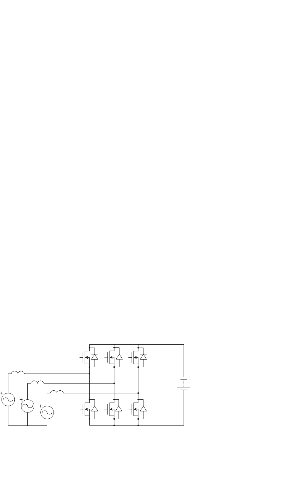
FIGURE 25.15 Model of an alternator with full-bridge converter.
The cylindrical rotor is made from steel laminations and the
field winding is placed in the rotor slots. The cylindrical rotor
is similar to the armature of a dc machine except that the
connection of the field winding to the external circuit is made
through slip rings instead of a commutator. The cylindrical
rotor structure leads to quiet operation and increased out-
put power and efficiency. Unlike the claw-pole alternator, the
length of the machine can be increased to get higher output
power at a higher efficiency. The efficiency is higher since the
effect of the end windings on the machine performance is less
in a machine with a long length. It is also possible to build
the machine with a salient-pole rotor instead of a cylindrical
rotor. However, a machine with a salient-pole rotor is likely to
produce more noise than a machine with a cylindrical rotor.
A machine with a cylindrical wound rotor has similar power
electronics and control options as a claw-pole machine. If
generation-only operation is required, a diode bridge and field
current control is sufficient to regulate the output voltage.
Better performance can be achieved by using a switched-mode
rectifier in conjunction with field control [37]. If motoring
operation is desired (e.g. for starting), or even better perfor-
mance is desired, a full-bridge (active-switch) converter can
be used, as shown in Fig. 25.15. Since this is a synchronous
machine, some form of rotor position sensing or estimation
is typically necessary. The full-bridge converter allows maxi-
mum performance and flexibility but carries a significant cost
penalty.
25.6.3.2 Induction Machine
The stator of a three-phase induction machine is similar to that
of a three-phase synchronous machine. The rotor is either a
squirrel-cage or wound rotor. The machine with the squirrel-
cage rotor is simpler in construction and more robust than the
machine with a wound rotor in which the three-phase rotor
winding is brought outside the rotor through slip rings. The
rotor is cylindrical and is constructed from steel laminations.
It is also possible to use a solid rotor instead of a laminated
rotor. However, a solid rotor leads to higher losses as compared
with a laminated rotor. The losses in a solid rotor can be

650 D. J. Perreault et al.
reduced by cutting slots in the rotor surface, filling the stator
slot openings with magnetic wedges to reduce the field ripple,
and placing a copper cage on the rotor.
An induction machine requires a source that can provide
the leading reactive power to magnetize the airgap. This means
that a three-phase induction generator cannot supply power to
a load through a three-phase diode bridge. Capacitor supply of
the reactive energy is impractical because of the wide operating
speed range. In the most general case (in which both motoring
and generating operation can be achieved) a three-phase active
bridge can be used. If only generating operation is desired,
the power to the load can be supplied through a three-phase
diode bridge and the reactive power can be obtained from a
small three-phase active bridge provided for this purpose. This
design requires a large number of devices and complex control.
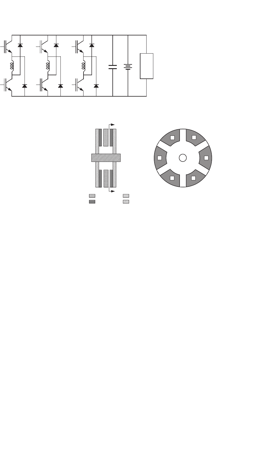
25.6.3.3 Reluctance Machines
The switched reluctance machine is a doubly salient machine.
Both the stator and rotor of the machine are made from steel
laminations to reduce the iron losses. Only the stator carries
windings; the rotor is constructed of steel laminations with a
salient shape. The structure of a three-phase switched reluc-
tance machine with six stator poles and four rotor poles is
shown in Fig. 25.16a. A winding placed on diametrically oppo-
site stator poles forms a phase winding. When a phase of
the machine is excited, a pair of rotor poles tends to align
with the excited stator poles to provide a path of minimum
reluctance. If the rotor is moving towards alignment with the
excited pair of stator poles, then the machine develops a pos-
itive torque and acts as a motor. If the rotor is moving away
from the excited pair of stator poles, then the machine devel-
ops a negative torque and acts as a generator. The advantages
of the switched reluctance machine include simple construc-
tion, fault-tolerant power electronic circuit, high reliability,
unidirectional phase currents, and low cost. The drawbacks of
the machine include high levels of torque ripple, vibration and
acoustic noise, and a relatively high power electronics cost.
The synchronous reluctance machine is a singly salient
machine. The stator of the machine is similar to that of
A
A
′
(a) (b)
FIGURE 25.16 Structures of: (a) switched reluctance and (b) synchro-
nous reluctance machines. AA
represents phase A winding.
a synchronous or induction machine. The rotor has a seg-
mented structure with each segment consisting of a stack of
axially laminated steel sheets sandwiched with a non-magnetic
material. The structure of a four-pole synchronous reluctance
machine is shown in Fig. 25.16b. A synchronous reluctance
machine has less torque ripple, lower losses, and higher power
density than a comparable switched reluctance machine. Inclu-
sion of permanent magnets in the rotor structure allows both
reluctance and magnet torque to be achieved. Such interior
permanent magnet (IPM) machines can achieve very high
performance and power density. When permanent magnets
are included, however, careful attention must be paid to the
effects of shutdown of the power electronics as an uncontrolled
back-emf component will exist in this case [41].
The switched reluctance machine, like the induction
machine, requires an external source to magnetize the airgap.
Several circuits are available to excite the switched reluctance
machine. A circuit that is suitable for the automotive appli-
cation of this machine is shown in Fig. 25.17. A phase leg
is needed for each stator phase of the machine. In this case,
the switched reluctance machine obtains its excitation from
the same bus that it generates into. Unlike the synchronous
and induction machines in which the number of wires needed
to connect the machines to the power converters is usually
equal to the number of phases, the number of wires needed
to connect the switched reluctance machine to a converter is
equal to twice the number of phases. This is of no particular
concern in a switched reluctance machine in which the power
converter is integrated with the machine in the same housing.
The synchronous reluctance machine also requires an external
source to magnetize the airgap. The machine usually employs
an active bridge similar to the one used with an induction
machine for the desired power conversion. The machine can
also employ the converters used with the switched reluctance
machine. In this case, the currents through the stator wind-
ings are unidirectional. The relative complexity of the power
electronics is a disadvantage of these machine types in the case
where only generator operation is necessary.
25.6.3.4 Permanent Magnet and Hybrid
Synchronous Machines
The permanent magnet synchronous machine designed with
high-energy rare-earth magnets operates with high efficiency,
high power density, low rotor inertia, and low acoustic noise.
The excitation from the permanent magnets is fixed and, there-
fore, the regulation of the output voltage of the machine is
not as straightforward as in a synchronous machine with a
wound rotor. For generator operation, machines of this type
can use switched-mode rectifiers to regulate the output volt-
age [42, 43]. The boost rectifier of Fig. 25.14 is one possible
implementation of this approach. Alternatively, a diode rec-
tifier followed by a dc/dc converter can be used to regulate
the generator system output [44]. Another method proposed
25 Automotive Applications of Power Electronics 651
L
o
a
d
Phase
A
Phase
B
Phase
C
FIGURE 25.17 Circuit for a switched reluctance machine.
for this type of system involves the use of tapped windings
and two three-phase SCR bridges [45]. The taps on the phase
windings are connected to one bridge, while full phase wind-
ings are connected to the other bridge. The bridge connected
to the full phase windings is used to supply power to the dc
bus at low engine speeds, while the converter connected to the
taps is used at high speed. The use of a tapped winding and
dual bridges helps the system cope with the wide speed range
of the alternator and limit the losses associated with the pul-
sating output currents. In the case when both motoring and
generating modes are desired, a full-bridge converter can be
used. Again, as this is a synchronous machine, some form of
position sensing or estimation is necessary. Also, in all of these
systems the effects of failure of the power electronics must be
carefully considered as there is no possibility of regulating the
back voltages by field control.
Attempts to develop a simpler voltage regulation scheme for
permanent magnet synchronous machines have led to a per-
manent magnet/wound-rotor hybrid synchronous machine in
which the rotor consists of two parts: a part with permanent
magnets and a part with a field winding [46]. The two parts
are placed next to each other on a common shaft. The rotor
with the field winding can employ claw-pole, salient-pole, or
cylindrical structure. The field current generates a flux that is
used to either aid or oppose the permanent magnet flux and
regulate the output voltage of the machine. One possible fail-
ure mode of this approach that can lead to catastrophic failure
is if the field winding breaks while the machine is operating
at high speed. In this case, the generated output voltage will
become large and uncontrolled. Some means of mechanically
disconnecting the alternator at the input or electrically discon-
necting it at the output may be necessary to limit the impact
of this failure mode.
25.6.3.5 Axial-airgap Machines
The principle of operation of an axial-airgap, or axial-flux,
machine is the same as that of a radial-airgap machine. An
axial-airgap machine is characterized by a short axial length
and large diameter. The structure of an axial-airgap per-
manent magnet machine with surface magnets is shown in
N
NS
N
S
S
Stator
Magnets
Rotor
Shaft
FIGURE 25.18 Structure of an axial-airgap permanent magnet
machine.
Fig. 25.18 [47]. The stator of the machine can be slotless or
slotted. Two different magnetic circuit configurations are pos-
sible. In the NN configuration, the magnetic polarities in one
pole pitch on both sides of stator are the same so that there
are two main fluxes with symmetrical distribution through
the stator. In this case, the conductors can be wound into two
back-to-back stator slots to make one coil. The machine has
a large stator yoke dimension because the flux passes through
the yoke, but less copper loss because of short end windings.
In the NS configuration, the magnetic polarities in one pole
pitch on the opposite sides of stator are the opposite of each
other so that there is only one main axial flux through the
stator. In this case, the stator yoke dimension is small, but
the end windings are long because the direction of current in
the back-to-back stator slots is the same. The iron losses are
small due to small yoke dimension and the copper losses are
high because of long end windings. Heat removal is more chal-
lenging due to small stator dimensions. The structure shown in
Fig. 25.18 is that of an axial-airgap permanent magnet machine
with surface magnets. In an axial-airgap machine with interior
permanent magnets, the magnets are embedded in the steel of
the rotor.
The axial airgap versions of other types of machines, such
as the induction and switched reluctance machines, are also
possible. The structure of an axial-airgap induction machine

652 D. J. Perreault et al.
is similar to that of an axial-airgap permanent magnet machine
except that windings are used instead of permanent magnets.
25.7 Dual/High Voltage Automotive
Electrical Systems
The electrical system of a 1920s internal combustion engine
(ICE) automobile had only a few loads: a starter, an ignition
device, a horn, and some lamps [48]. The mean power con-
sumption of these loads was less than 100 W. An engine-driven
dc generator charged a 6 V lead-acid battery that provided
electrical power. The power was distributed via point-to-point
wiring, with most loads controlled directly by manually oper-
ated primary switches located within the reach of the driver.
Only the starter was switched indirectly by an electromechan-
ical relay. After the Second World War, the automotive elec-
trical system started to grow rapidly in complexity and power
consumption as additional features, including radios, multi-
speed windshield wipers, and power windows, were added. The
introduction of higher compression engines stretched the 6-V
system beyond its technological limits. The 8.5 to 1 compres-
sion ratio engines required 100–200% greater ignition voltages
than the 6.4 to 1 engines. As a result, the primary side cur-
rent of the ignition coil was doubled or tripled and the life of
the distributor contacts was reduced to an unacceptable level.
To overcome this problem, the battery voltage was increased
to 12 V in the mid-1950s [49, 50].
Over the past four decades, the electrical power require-
ments of automobiles have increased even more rapidly. From
a mere 400 W in 1955, the power rating of a luxury vehicle’s
generator has increased to over 1800 W [51, 52]. However,
the electrical system of a modern automobile is architecturally
identical to the 12-V point-to-point system of the 1950s. The
only changes that have taken place have been at the compo-
nent level, such as the replacement of the dc generator by
a three-phase alternator-rectifier, the replacement of wound-
field dc motors by permanent magnet ones, and an increased
use of relays. The rapid growth in the electrical system is
expected to continue due to environmental regulations, con-
sumer demand for increased functionality, safety, security and
comfort, and replacement of some mechanical actuators by
electrical counterparts. The average electrical power require-
ment of a modern luxury vehicle is about 800 W. With the
addition of such loads as electric power steering, engine-
cooling fan, water pump, and electromechanical engine valves,
the average power requirement could increase to 2.5 kW by
2005 [53]. The traditional solution of increasing the size of the
alternator and the battery is not practical due to space limita-
tions and fuel efficiency requirements. Furthermore, the peak
power requirements of some of the anticipated loads – heated
windshield (2.5 kW), heated catalyst (3 kW), electromechani-
cal engine valves (2.4 kW at 3000 rpm), and active suspension
(12 kW) – cannot be met economically using the present
architecture. These factors have motivated the development
of new dual/high voltage electrical architectures that incorpo-
rate a higher-voltage bus in addition to the standard 14 V bus
[39, 54–56]. A dual/high voltage approach allows an efficient
supply of power to many loads which benefit from operat-
ing at a higher voltage, while retaining the 14 V bus for loads
(such as lamps and electronics) which do not benefit from a
higher voltage. High-voltage architectures that do not retain
the 14 V bus are also possible, but will require a substantial
investment in the design and production of new high-voltage
components. This section describes some of the characteristics
and preliminary specifications of the new dual/high voltage
electrical system architectures. It also discusses some of the
widely considered implementation approaches.
25.7.1 Trends Driving System Evolution
The conventional 12-V automotive electrical power system has
many defects, including a widely varying steady-state system
voltage and large transients, which force the electrical func-
tions to be over-designed. However, these limitations alone
have not been a strong enough driver for automotive compa-
nies to seriously evaluate advanced alternatives. Now a number
of new factors are changing this situation. The most important
of these are future load requirements that cannot be met by
the present 12-V architecture.
25.7.1.1 Future Load Requirements
Table 25.6 gives a list of electrical loads expected to be intro-
duced into automobiles in the next ten years [53]. Some of
these loads (electrohydraulic power steering, electric engine
fan, electric water pump, and electromechanical valves) will
replace existing mechanically or hydraulically driven loads.
The remaining are new loads introduced to either meet
government mandates or satisfy customer needs.
TABLE 25.6 Electrical loads expected to be introduced into automobiles
in the next decade [53]
Load Peak power (W) Average power (W)
Exhaust air pump 300 10
Electrohydraulic power
steering
1000 150
Electric engine fan 800 150
Heated catalytic converter 3000 90
Electric water pump 300 150
Heated windshield 2500 120
Electromechanical engine
valves (6 cylinders at
6000 rpm)
2400 800
Active suspension 12,000 360
Total 1830