Power electronic handbook
Подождите немного. Документ загружается.

694 C. V. Nayar et al.
PV panels
+
−
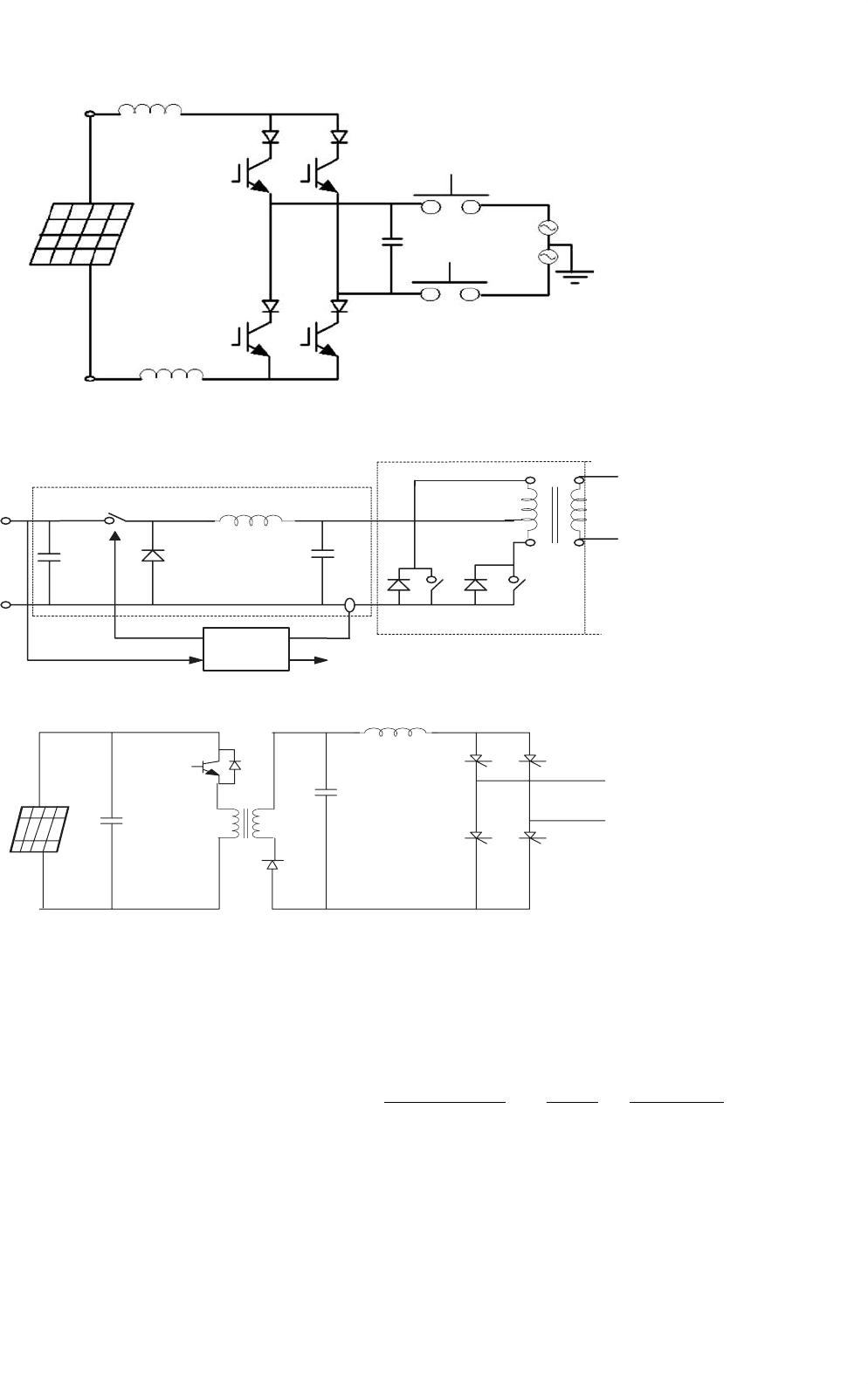
FIGURE 27.38 Non-insulated current source.
Controller
Grid
V
pv
C
1
C
2
D
S
1
S
2
S
3
L
I
I
1
Transformer
S
2
, S
3
Buck Converter
Half Bridge
FIGURE 27.39 Buck converter with half-bridge transformer link.
PV
Panel
240V, AC
Mains
FIGURE 27.40 Flyback converter.
Figure 27.43 shows the simplified/equivalent schematic dia-
gram of a VCVSI. For the following analysis it is assumed
that the output low-pass filters (L
f
and C
f
) of VSIs will filter
out high-order harmonics generated by PWMs. The decou-
pling inductor (X
m
) is an essential part of any VCVSI as it
makes the power flow control possible. In a VCVSI, the power
flow of the distributed generation system (DGS) is controlled
by adjusting the amplitude and phase (power angle (δ)) of
the inverter output voltage with respect to the grid voltage.
Hence, it is important to consider the proper sizing of the
decoupling inductor and the maximum power angle to provide
the required power flow when designing VCVSIs. The phasor
diagram of a simple grid-inverter interface with a first-order
filter are shown in Fig. 27.44.
Referring to Fig. 27.43, the fundamental grid current (I
g
)
can be expressed by Eq. (27.7):
I
g
=
V
g
< 0 −V
c
<δ
jX
m
=−
V
c
sin δ
X
m
−j
V
g
−V
c
cos δ
X
m
(27.7)
where V
g
and V
c
are respectively the grid and the VCVSI’s
fundamental voltages, and X
m
is the decoupling induc-
tor impedance. Using per unit values (S
base
= V
2
base
/Z
base
,
27 Power Electronics for Renewable Energy Sources 695
Grid
To other
Units
PV Unit
Transformer
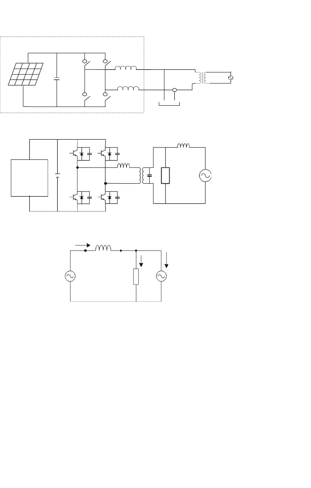
FIGURE 27.41 Converter using parallel PV units.
Renewable
Energy Sources
(RES)
Load
Grid
L
f
Cf
X
m
V
Bat
FIGURE 27.42 Schematic diagram of a parallel processing DGS.
1
2
Load
I
Load
I
g
I
c
V
inv
= V
c
sin(wt d)
X
m
V
x
−
+
−
+
V
grid
= V
g
sin wt
=V
g
∠0
−
+
=V
c
∠ d
FIGURE 27.43 The equivalent circuit diagram of a VCVSI.
V
base
= V
c
, and Z
base
= X
m
) where V
base
, Z
base
, and S
base
are the base voltage, impedance and complex power values
respectively. The grid apparent power can be expressed as
Eq. (27.8).
S
gpu
=−V
gpu
sin δ +j(V
2
gpu
−V
gpu
cos δ) (27.8)
Using per unit values, the complex power of the VCVSI and
decoupling inductor are
S
cpu
=−V
gpu
sin δ +j(V
gpu
cos δ −1) (27.9)
S
xpu
= j(V
2
gpu
−2V
gpu
cos δ +1) (27.10)
where S
gpu
, S
cpu
, and S
xpu
are per unit values of the grid,
VCVSI, and decoupling inductor apparent power respectively,
and V
gpu
is the per unit value of the grid voltage.
Figure 27.45 shows the equivalent schematic diagram of a
CCVSI. As a CCVSI controls the current flow using the VSI
switching instants, it can be modeled as a current source and
there is no need for a decoupling inductor (Fig. 27.45). As
the current generated from the CCVSI can be controlled inde-
pendently from the AC voltage, the active and reactive power
controls are decoupled. Hence, unity power factor operation
is possible for the whole range of the load. This is one of the
main advantages of CCVSIs.
As the CCVSI is connected in parallel to the DGS, it follows
the grid voltage. Figure 27.46 shows the phasor diagram of a
696 C. V. Nayar et al.
V
c1
I
gq2
I
gq2
I
gp3
=I
gp2
=I
gp1
I
g1
α
2
I
g2
V
g1
V
g2
V
g3
V
x1
V
x2
V
x3
V
c2
V
c3
I
g3
δ
1
δ
3
δ
2
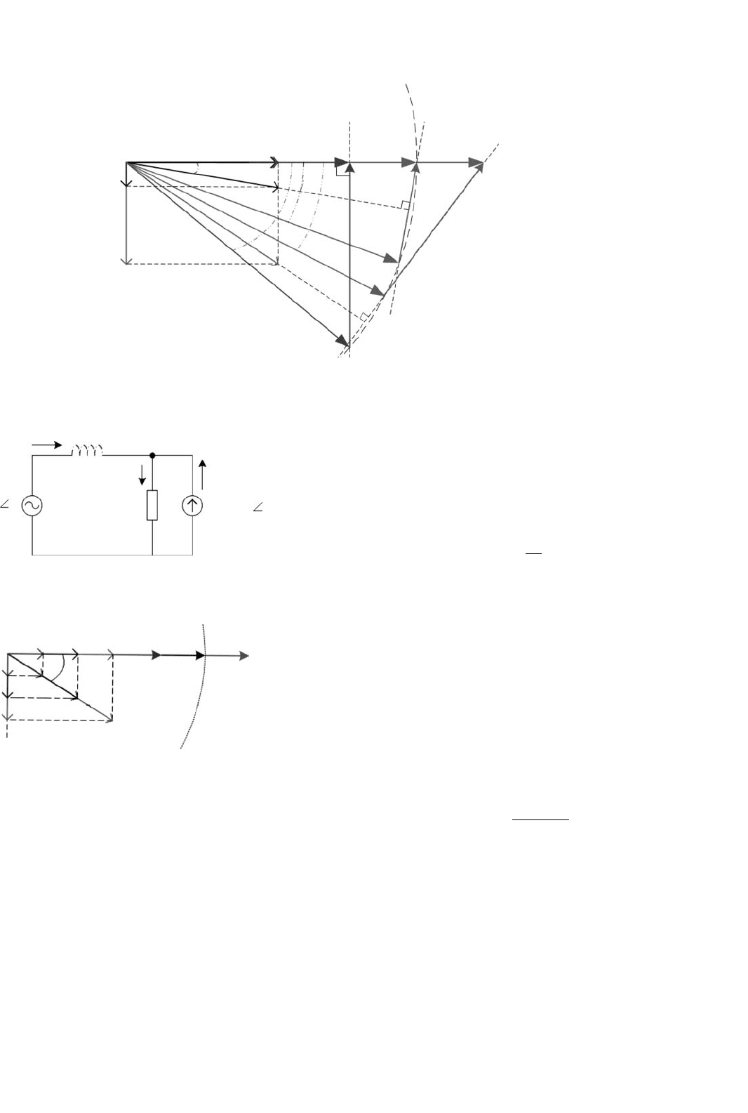
FIGURE 27.44 Phasor diagram of a VCVSI with resistive load and assuming the grid is responsible for supplying the active power [46].
Load
X
m=0
I
g
I
L
I
c
V
grid
= V 0
V
inv
= V 0
FIGURE 27.45 The equivalent circuit of a CCVSI.
I
g1
I
g2
I
g3
V
g1
V
g2
V
g3
I
L3
I
L2
I
L1
I
cq1
I
cq2
I
cq3
q
FIGURE 27.46 Phasor diagram of a CCVSI with inductive load and
assuming grid is responsible for supplying the active power [46].
CCVSI based DGS in the presence of an inductive load (con-
sidering the same assumption as VCVSI section). Figure 27.49
shows that when the grid voltage increases, the load’s active
power consumption, which supplied by the grid increases and
the CCVSI compensates the increase in the load reactive power
demand. In this case, the CCVSI maintains grid supply at unity
power factor, keeping the current phase delay with respect to
the grid voltage at a fixed value (θ). Therefore, the CCVSI can-
not maintain the load voltage in the presence of a DGS without
utilizing extra hardware and control mechanisms. This limita-
tion on load voltage stabilization is one of the main drawbacks
of CCVSI based DGS.
Assuming the load active current demand is supplied by
the grid (reactive power support function), the required grid
current can be rewritten as follows
I
∗
g
= Re
[
I
L
]
= Re
S
L
V
g
(27.11)
where, S
L
is the demanded load apparent power. For grid
power conditioning, it is preferred that the load operate at
unity power factor. Therefore, the CCVSI must provide the
remainder of the required current Eq. (27.12)
I
c
= I
L
−I
∗
g
(27.12)
For demand side management (DSM), it is desirable to
supply the active power by the RES, where excess energy from
the RES is injected into the DGS. The remaining load reactive
power will be supplied by the CCVSI. Hence Eq. (27.12) can
be rewritten as Eq. (27.13).
I
∗
g
= Re
[
I
L
]
−Re
[
I
c
]
= Re
S
L
−P
RES
V
g
(27.13)
When using a voltage controller for grid-connected PV
inverter, it has been observed that a slight error in the phase
of synchronizing waveform can grossly overload the inverter
whereas a current controller is much less susceptible to voltage
phase shifts [45]. Due to this reason, the current controllers
are better suited for the control of power export from the PV
inverters to the utility grid since they are less sensitive to errors
in synchronizing sinusoidal voltage waveforms.
27 Power Electronics for Renewable Energy Sources 697
A prototype current-controlled type power conditioning
system has been developed by the first author and tested on
a weak rural feeder line at Kalbarri in Western Australia [47].
The choice may be between additional conventional generating
capacity at a centralized location or adding smaller distributed
generating capacities using RES like PV. The latter option can
have a number of advantages like:
• The additional capacity is added wherever it is required
without adding additional power distribution infrastruc-
ture. This is a critical consideration where the power
lines and transformers are already at or close to their
maximum ratings.
• The power conditioning system can be designed to pro-
vide much more than just a source of real power, for
minimal extra cost. A converter providing real power
needs only a slight increase in ratings to handle signif-
icant amounts of reactive or even harmonic power. The
same converter that converts DC PV power to AC power
can simultaneously provide the reactive power support
to the week utility grid.
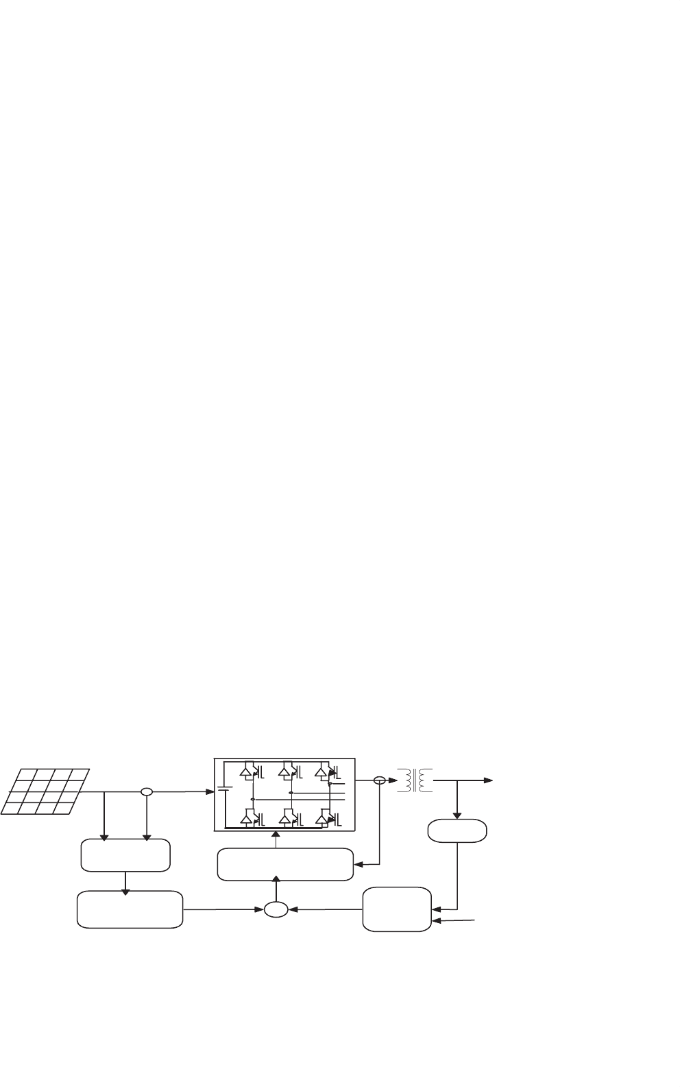
The block diagram of the power conditioning system used
in the Kalbarri project has been shown in the Fig. 27.47. This
CCVSI operates with a relatively narrow switching frequency
band near 10 kHz. The control diagram indicates the basic
operation of the power conditioning system. The two outer
control loops operate to independently control the real and
reactive power flow from the PV inverter. The real power is
controlled by an outer MPPT algorithm with an inner DC
link voltage control loop providing the real current magni-
tude request I
∗
p
and hence the real power export through PV
converter is controlled through the DC link voltage regula-
tion. The DC link voltage is maintained at a reference value
by a PI control loop, which gives the real current reference
magnitude as it’s output. At regular intervals, the DC link
voltage is scanned over the entire voltage range to check that
the algorithm is operating on the absolute MPP and is not
stuck around a local MPP. During the night, the converter can
S
1
S
3
S
5
S
2
S
4
S
6
V
dc
MPPT
control
Real
current control
CC-VSI with
ZACE control
Reactive
current
control
RMS
20 kW
PV Array
180−380
V
dc
V
dc
*
I
P
*I
Q
*
I
ac
*
V
ac
*
415V
ac
FIGURE 27.47 Block diagram of Kalbarri power conditioning system.
still be used to regulate reactive power of the grid-connected
system although it cannot provide active power. During this
time, the PI controller maintain a minimum DC link voltage
to allow the power conditioning system to continue to operate,
providing the necessary reactive power.
The AC line voltage regulation is provided by a separate
reactive power control, which provides the reactive current
magnitude reference I
∗
Q
. The control system has a simple trans-
fer function, which varies the reactive power command in
response to the AC voltage fluctuations. Common to the outer
real and reactive power control loops is an inner higher band-
width zero average current error (ZACE) current control loop.
I
∗
p
is in phase with the line voltages, and I
∗
Q
is at 90
◦
to the line
voltage. These are added together to give one (per phase) sinu-
soidal converter current reference waveform (I
∗
ac
). The CCVSI
control consists of analog and digital circuitry which acts as
a ZACE transconductance amplifier in converting I
∗
ac
into AC
power currents [48].
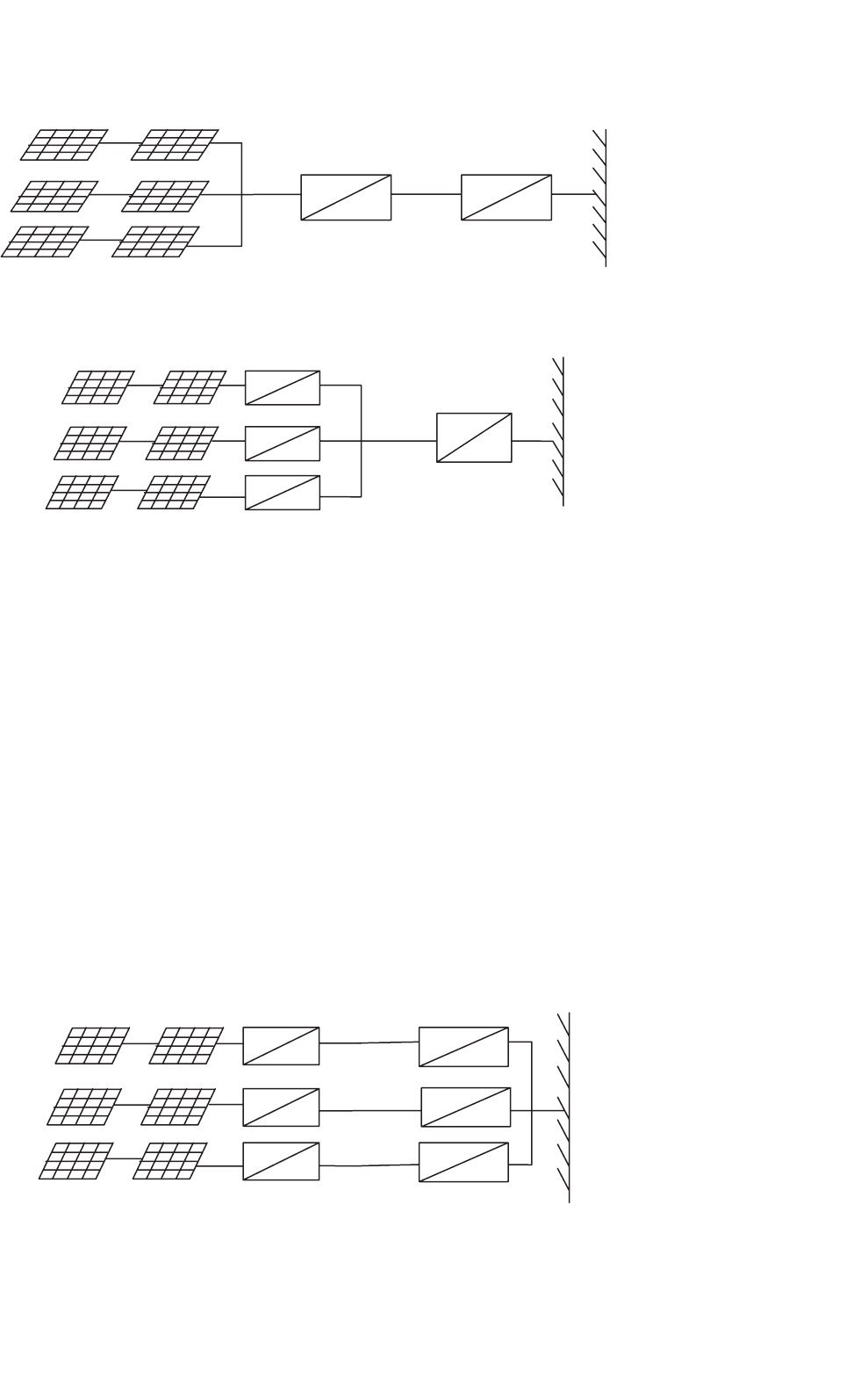
27.2.5.5 System Configurations
The utility compatible inverters are used for power condition-
ing and synchronization of PV output with the utility power.
In general, four types of battery-less grid-connected PV system
configurations have been identified:
• Central plant inverter.
• Multiple string DC/DC converter with single output
inverter.
• Multiple string inverter.
• Module integrated inverter.
27.2.5.5.1 Central Plant Inverter In the central plant
inverter, usually a large inverter is used to convert DC power
output of PV arrays to AC power. In this system, the PV mod-
ules are serially stringed to form a panel (or string) and several
such panels are connected in parallel to a single DC bus. The
block diagram of such a scheme is shown in Fig. 27.48.
698 C. V. Nayar et al.
String 1
String 2
String 3
MPPT Inverter
Grid
=
=
=
~
FIGURE 27.48 Central plant inverter.
String 1
String 2
String 3
MPPT
Inverter
Grid
=
=
=
=
=
=
=
~
String 1
String 2
String 3
MPPT
Inverter
Grid
=
=
=
=
=
=
=
~
FIGURE 27.49 Multiple string DC/DC converter.
27.2.5.5.2 Multiple String DC/DC Converter In multiple
string DC/DC converter, as shown in Fig. 27.49, each string
will have a boost DC/DC converter with transformer iso-
lation. There will be a common DC link, which feeds a
transformer-less inverter.
27.2.5.5.3 Multiple String Inverters Figure 27.50 shows the
block diagram of multiple string inverter system. In this
scheme, several modules are connected in series on the DC
side to form a string. The output from each string is converted
to AC through a smaller individual inverter. Many such invert-
ers are connected in parallel on the AC side. This arrangement
is not badly affected by the shading of the panels. It is also not
seriously affected by inverter failure.
String 1
String 2
String 3
MPPT Inverter
Grid
=
=
=
=
=
=
=
~
=
~
=
~
FIGURE 27.50 Multiple string inverter.
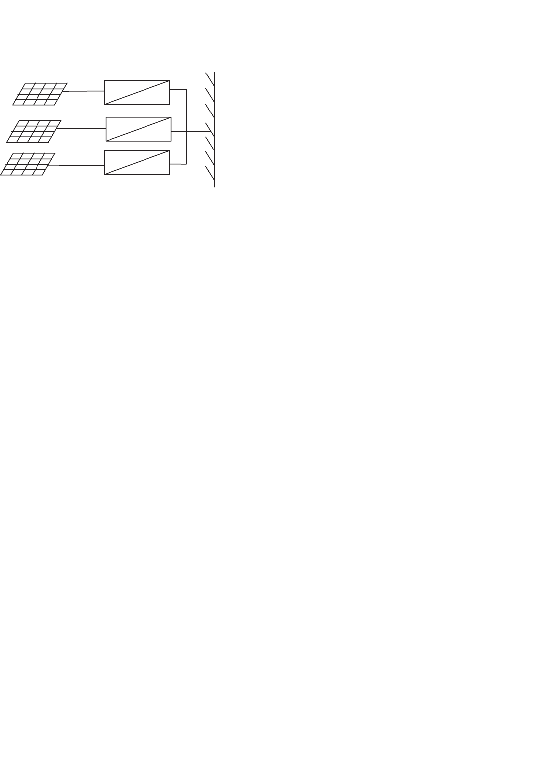
27.2.5.5.4 Module Integrated Inverter In the module inte-
grated inverter system (Fig. 27.51), each module (typically
50–300 W) will have a small inverter. No cabling is required.
It is expected that high volume of small inverters will bring
down the cost.
27.2.5.6 Grid-compatible Inverters Characteristics
The characteristics of the grid-compatible inverters are:
• Response time.
• Power factor.
• Frequency control.
• Harmonic output.
• Synchronization.
• Fault current contribution.
27 Power Electronics for Renewable Energy Sources 699
Module 1
Module 2
Module 3
Inverter
Grid
=
~
=
~
=
~
FIGURE 27.51 Module integrated inverter.
• DC current injection.
• Protection.
The response time of the inverters shall be extremely fast
and governed by the bandwidth of the control system. Absence
of rotating mass and use of semiconductor switches allow
inverters to respond in millisecond time frame. The power fac-
tor of the inverters is traditionally poor due to displacement
power factor and the harmonics. But with the latest devel-
opment in the inverter technology, it is possible to maintain
the power factor close to unity. The converters/inverters have
the capability of creating large voltage fluctuation by draw-
ing reactive power from the utility rather than supplying [49].
With proper control, inverters can provide voltage support
by importing/exporting reactive power to push/pull towards a
desired set point. This function would be of more use to the
utilities as it can assist in the regulation of the grid system at
the domestic consumer level.
Frequency of the inverter output waveshape is locked to
the grid. Frequency bias is where the inverter frequency is
deliberately made to run at 53 Hz. When the grid is present,
this will be pulled down to the nominal 50 Hz. If the grid fails,
it will drift upwards towards 53 Hz and trip on over frequency.
This can help in preventing islanding.
Harmonics output from the inverters have been very poor
traditionally. Old thyristor-based inverters are operated with
slow switching speeds and could not be pulse width mod-
ulated. This resulted in inverters known as six-pulse or
twelve-pulse inverters. The harmonics so produced from the
inverters can be injected into the grid, resulting in losses, heat-
ing of appliances, tripping of protection equipments, and poor
power quality. The number of pulses being the number of steps
in a sine-wave cycle. With the present advent in the power
electronics technology, the inverter controls can be made very
good. Pulse width modulated inverters produce high quality
sine waves. The harmonic levels are very low, and can be lower
than the common domestic appliances. If the harmonics are
present in the grid voltage waveform, harmonic currents can
be induced in the inverter. These harmonic currents, particu-
larly those generated by a voltage-controlled inverter, will in
fact help in supporting the grid. These are good harmonic cur-
rents. This is the reason that the harmonic current output of
inverters must be measured onto a clean grid source so that the
only harmonics being produced by the inverters are measured.
Synchronization of inverter with the grid is performed auto-
matically and typically uses zero crossing detection on the
voltage waveform. An inverter has no rotating mass and hence
has no inertia. Synchronization does not involve the accel-
eration of a rotating machine. Consequently the reference
waveforms in the inverter can be jumped to any point required
within a sampling period. If phase-locked loops are used, it
could take up a few seconds. Phase-locked loops are used to
increase the immunity to noise. This allows the synchroniza-
tion to be based on several cycles of zero crossing information.
The response time for this type of locking will be slower.
Photovoltaic panels produce a current that is proportional
to the amount of light falling on them. The panels are normally
rated to produce 1000 W/m
2
at 25
◦
C. Under these conditions,
the short-circuit current possible from these panels is typi-
cally only 20% higher than the nominal current whereas it is
extremely variable for wind. If the solar radiation is low then
the maximum current possible under short-circuit is going to
be less than the nominal full load current. Consequently PV
systems cannot provide the short-circuit capacity to the grid.
If a battery is present, the fault current contribution is lim-
ited by the inverter. With the battery storage, it is possible for
the battery to provide the energy. However, inverters are typ-
ically limited between 100 and 200% of nominal rating under
current limit conditions. The inverter needs to protect itself
against the short circuits because the power electronic com-
ponents will typically be destroyed before a protection device
like circuit breaker trips.
In case of inverter malfunction, inverters have the capability
to inject the DC components into the grid. Most utilities have
guidelines for this purpose. A transformer shall be installed at
the point of connection on the AC side to prevent DC from
being entering into the utility network. The transformer can
be omitted when a DC detection device is installed at the point
of connection on the AC side in the inverter. The DC injec-
tion is essentially caused by the reference or power electronics
device producing a positive half cycle that is different from
the negative half cycle resulting in the DC component in the
output. If the DC component can be measured, it can then be
added into the feedback path to eliminate the DC quantity.
27.2.5.6.1 Protection Requirements A minimum require-
ment to facilitate the prevention of islanding is that the inverter
energy system protection operates and isolates the inverter
energy system from the grid if:
• Over voltage.
• Under voltage.

700 C. V. Nayar et al.
• Over frequency.
• Under frequency exists.
These limits may be either factory set or site programmable.
The protection voltage operating points may be set in a nar-
rower band if required, e.g. 220–260 V. In addition to the
passive protection detailed above, and to prevent the situation
where islanding may occur because multiple inverters provide
a frequency reference for one another, inverters must have
an accepted active method of islanding prevention following
grid failure, e.g. frequency drift, impedance measurement, etc.
Inverter controls for islanding can be designed on the basis
of detection of grid voltage, measurement of impedance, fre-
quency variation, or increase in harmonics. This function must
operate to force the inverter output outside the protection tol-
erances specified previously, thereby resulting in isolation of
the inverter energy system from the grid. The maximum com-
bined operation time of both passive and active protections
should be 2 s after grid failure under all local load conditions.
If frequency shift is used, it is recommended that the direction
of shift be down. The inverter energy system must remain dis-
connected from the grid until the reconnection conditions are
met. Some inverters produce high voltage spikes, especially at
light load, which can be dangerous for the electronic equip-
ment. IEEE P929 gives some idea about the permitted voltage
limits.
If the inverter energy system does not have the above fre-
quency features, the inverter must incorporate an alternate
anti-islanding protection feature that is acceptable to the rel-
evant electricity distributor. If the protection function above
is to be incorporated in the inverter it must be type tested
for compliance with these requirements and accepted by the
relevant electricity distributor. Otherwise other forms of exter-
nal protection relaying are required which have been type
tested for compliance with these requirements and approved
by the relevant electricity distributor. The inverter shall have
adequate protection against short circuit, other faults, and
overheating of inverter components.
27.3 Power Electronics for Wind
Power Systems
In rural USA, the first wind mill was commissioned in 1890 to
generate electricity. Today, large wind generators are compet-
ing with utilities in supplying clean power economically. The
average wind turbine size has been 300–600 kW until recently.
The new wind generators of 1–3 MW have been developed
and are being installed worldwide, and prototype of even
higher capacity is under development. Improved wind tur-
bine designs and plant utilization have resulted in significant
reduction in wind energy generation cost from 35 cents per
kWh in 1980 to less than 5 cents per kWh in 1999, in locations
where wind regime is favorable. At this generation cost, wind
energy has become one of the least cost power sources. Main
factors that have contributed to the wind power technology
development are:
• High strength fiber composites for manufacturing large
low-cost blades.
• Variable speed operation of wind generators to capture
maximum energy.
• Advancement in power electronics and associated cost.
•
Improved plant operation and efficiency.
• Economy of scale due to availability of large wind
generation plants.
• Accumulated field experience improving the capacity
factor.
• Computer prototyping by accurate system modeling and
simulation.
The Table 27.2 is for wind sites with average annual wind
speed of 7 m/s at 30 m hub height. Since 1980s, wind technol-
ogy capital costs have reduced by 80% worldwide. Operation
and maintenance costs have declined by 80% and the avail-
ability factor of grid-connected wind plants has increased to
95%. At present, the capital cost of wind generator plants has
dropped to about $600 per kW and the electricity generation
cost has reduced to 6 cents per kWh. It is expected to reduce
the generation cost below 4 cents per kWh. Keeping this in
view, the wind generation is going to be highly competitive
with the conventional power plants. In Europe, USA, and Asia
the wind power generation is increasing rapidly and this trend
is going to continue due to economic viability of wind power
generation.
TABLE 27.2 Wind power technology developments
1980 1999 Future
Cost per kWh $0.35–0.40 $0.05–0.07 <$0.04
Capital cost per kW $2000–3000 $500–700 <$400
Operating life 5–7 Years 20 Years 30 Years
Capacity factor (average) 15% 25–30% >30%
Availability 50–65% 95% >95%
Wind turbine unit size
range
50–150 kW 300–1000 kW 500–2000 kW
The technical advancement in power electronics is play-
ing an important part in the development of wind power
technology. The contribution of power electronics in control
of fixed speed/variable speed wind turbines and interfac-
ing to the grid is of extreme importance. Because of the
fluctuating nature of wind speed, the power quality and
reliability of the wind based power system needs to be eval-
uated in detail. Appropriate control schemes require power
conditioning.
27 Power Electronics for Renewable Energy Sources 701
27.3.1 Basics of Wind Power
The ability of a wind turbine to extract power from wind is a
function of three main factors:
•
Wind power availability.
• Power curve of the machine.
• Ability of the machine to respond to wind perturbations.
The mechanical power produced by a wind turbine is
given by
P
m
= 0.5ρC
p
AU
3
W (27.14)
The power from the wind is a cubic function of wind speed.
The curve for power coefficient C
p
and λ is required to infer
the value of C
p
for λ based on wind speed at that time.
Where tip speed ratio, λ =
rω
A
U
, ρ = Air density, Kg m
−3
,
C
p
= power coefficient, A = wind turbine rotor swept area,
m
2
, U = wind speed in m/s.
The case of a variable speed wind turbine with a pitch mech-
anism that alters the effective rotor dynamic efficiency, can be
easily considered if an appropriate expression for C
p
as a func-
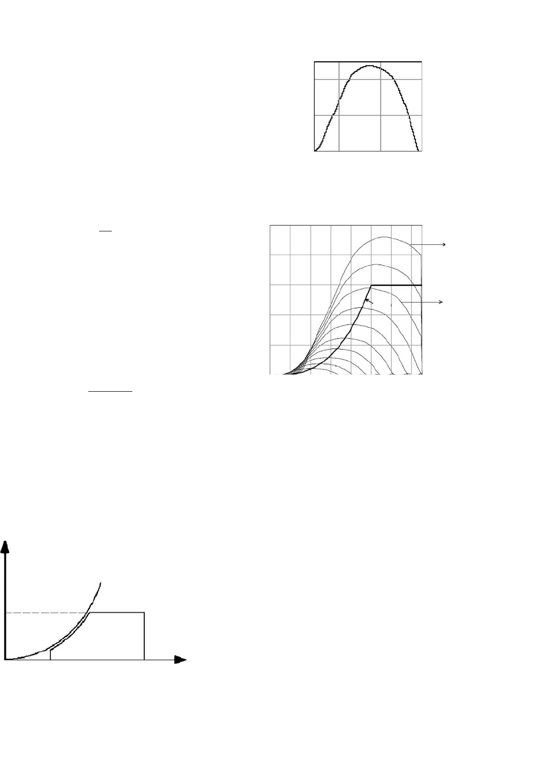
tion of the pitch angle is applied. The power curve of a typical
wind turbine is given in Fig. 27.52 as a function of wind speed.
The C
p
–λ curve for 150 kW windmaster machine is given in
Fig. 27.53, which has been inferred from the power curve of
the machine. The ratio of shaft power to the available power in
the wind is the efficiency of conversion, known as the power
coefficient C
p
C
p
=
P
m
(1/2ρAU
3
)
(27.15)
The power coefficient is a function of turbine blade tip speed
to wind speed ratio (β). A tip speed ratio of 1 means the blade
tips are moving at the same speed as the wind and when β
is 2 the tips are moving at twice the speed of the wind and
so on [51]. Solidity (σ) is defined as the ratio of the sum of
the width of all the blades to the circumference of the rotor.
Hence,
σ = Nd/(2πR) (27.16)
where N = number of blades and d = width of the blades.
Power
rated power
cut-in cut-out wind speed
wind turbine power
aerodynamic power
FIGURE 27.52 Power curve of wind turbine as a function of wind
speed [50].
0.5
0.4
0.2
C
p
0
25
λ
10 15
FIGURE 27.53 Cp–λ curve of wind machine [50].
400
500
300
200
100
0
0
v2
v1
v3
v4
v5
v6
v7
v8
v9
v10
200 400
Ptarget
600
Generator Shaft Speed (rpm)
Turbine Power (kW)
800 1000 1200 1400
12 m/s
14 m/s
FIGURE 27.54 Turbine power vs shaft speed curves.
The power from a wind turbine doubles as the area swept by
the blades doubles. But doubling of the wind speed increases
the power output eight times. Figure 27.54 gives a family of
power curves for a wind turbine. If the loading of the turbine is
controlled such that the operating point is along the maximum
power locus at different wind speeds, then the wind energy
system will be more efficient.
27.3.1.1 Types of Wind Turbines
There are two types of wind turbines available Fig. 27.55:
• Horizontal axis wind turbines (HAWTs).
• Vertical axis wind turbines (VAWTs).
Vertical axis wind turbines (VAWTs) have an axis of rota-
tion that is vertical, and so, unlike the horizontal wind
turbines, they can capture winds from any direction with-
out the need to reposition the rotor when the wind direction
changes (without a special yaw mechanism). Vertical axis wind
turbines were also used in some applications as they have the
advantage that they do not depend on the direction of the
wind. It is possible to extract power relatively easier. But there

702 C. V. Nayar et al.
Rotor blade
Rotor diameter
Rotor
diameter
Hub
height
Wind direction
of a downwind
rotor
Gearbox
Wind direction
for an upwind
rotor
Generator
Nacelle
Tower
Horizontal-axis wind turbine
(HAWT)
Vertical-axis wind turbine
(VAWT)
Rotor base
Gearbox
Generator
Equator
height
Fixed pitch
rotor blade
Rotor
tower
Rotor
height
FIGURE 27.55 Typical diagram of HAWTs and VAWTs.
are some disadvantages such as no self starting system, smaller
power coefficient than obtained in the horizontal axis wind
turbines, strong discontinuation of rotations due to periodic
changes in the lift force, and the regulation of power is not yet
satisfactory.
The horizontal axis wind turbines are generally used. Hor-
izontal axis wind turbines are, by far, the most common
design. There are a large number of designs commercially
available ranging from 50 W to 4.5 MW. The number of blades
ranges from one to many in the familiar agriculture windmill.
The best compromise for electricity generation, where high
rotational speed allows use of a smaller and cheaper electric
generator, is two or three blades. The mechanical and aerody-
namic balance is better for three bladed rotor. In small wind
turbines, three blades are common. Multiblade wind turbines
are used for water pumping on farms.
Based on the pitch control mechanisms, the wind turbines
can also be classified as:
• Fixed pitch wind turbines.
• Variable pitch wind turbines.
Different manufacturers offer fixed pitch and variable pitch
blades. Variable pitch is desirable on large machines because
the aerodynamic loads on the blades can be reduced and when
used in fixed speed operation they can extract more energy.
But necessary mechanisms require maintenance and for small
machines, installed in remote areas, fixed pitch seems more
desirable and economical. In some machines, power output
regulation involves yawing blades so that they no longer point
into the wind. One such system designed in Western Australia
has a tail that progressively tilts the blades in a vertical plane
so that they present a small surface to the wind at high speeds.
The active power of a wind turbine can be regulated by
either designing the blades to go into an aerodynamic stall
beyond the designated wind speed, or by feathering the blades
out of the wind, which results in reducing excess power using a
mechanical and electrical mechanism. Recently, an active stall
has been used to improve the stability of wind farms. This stall
mechanism can prevent power deviation from gusty winds to
pass through the drive train [52].
Horizontal axis wind turbines can be further classified into
fixed speed (FS) or variable speed (VS). The FS wind turbine
generator (FSWT) is designed to operate at maximum effi-
ciency while operating at a rated wind speed. In this case, the
optimum tip-speed ratio is obtained for the rotor airfoil at a
rated wind speed. For a VS wind turbine generator (VSWT),
it is possible to obtain optimum wind speed at different wind
speeds. Hence this enables the VS wind turbine to increase
its energy capture. The general advantages of a VSWT are
summarized as follows:
•
VSWTs are more efficient than the FSWTs.
• At low wind speeds the wind turbines can still capture the
maximum available power at the rotor, hence increas-
ing the possibility of providing the rated power for wide
speed range.
27 Power Electronics for Renewable Energy Sources 703
27.3.1.2 Types of Wind Generators
Schemes based on permanent magnet synchronous genera-
tors (PMSG) and induction generators are receiving close
attention in wind power applications because of their qual-
ities such as ruggedness, low cost, manufacturing simplicity,
and low maintenance requirements. Despite many positive
features over the conventional synchronous generators, the
PMSG was not being used widely [23]. However, with the
recent advent in power electronics, it is now possible to
control the variable voltage, variable frequency output of
PMSG. The permanent magnet machine is generally favored
for developing new designs, because of higher efficiency and
the possibility of a rather smaller diameter. These PMSG
machines are now being used with variable-speed wind
machines.
In large power system networks, synchronous generators
are generally used with fixed-speed wind turbines. The syn-
chronous generators can supply the active and reactive power
both, and their reactive power flow can be controlled. The
synchronous generators can operate at any power factor. For
the induction generator, driven by a wind turbine, it is a
well-known fact that it can deliver only active power, while
consuming reactive power
Synchronous generators with high power rating are signif-
icantly more expensive than induction generators of similar
size. Moreover, direct connected synchronous generators have
the limitation of rotational speed being fixed by the grid fre-
quency. Hence, fluctuation in the rotor speed due to wind
gusts lead to higher torque in high power output fluctuations
and the derived train. Therefore in grid-connected application,
Speed
Sensor
Slip
Power
Wound
Rotor
Induction
Generator
Rotor Side
Converter
(RSC)
S1a S2a S3a S1b S2b S3b
+
−
Front End
Converter
(FEC)
Series
Inductors
Digital Controller
Three-phase
Transformer
Grid
i
g1
i
g2
i
g3
i
r1
U
dc
i
r2
i
r3
i
g1
i
g2
i
g3
i
g1
i
g2
i
g3
FIGURE 27.56 Variable speed doubly-fed induction generator (VSDFIG) system.
synchronous generators are interfaced via power converters
to the grid. This also allows the synchronous generators to
operate wind turbines in VS, which makes gear-less operation
of the VSWT possible.
The squirrel-cage induction generators are widely used with
the fixed-speed wind turbines. In some applications, wound
rotor induction generators have also been used with adequate
control scheme for regulating speed by external rotor resis-
tance. This allows the shape of the torque-slip curve to be
controlled to improve the dynamics of the drive train. In
case of PMSG, the converter/inverter can be used to con-
trol the variable voltage, variable frequency signal of the
wind generator at varying wind speed. The converter con-
verts this varying signal to the DC signal and the output of
converter is converted to AC signal of desired amplitude and
frequency.
The induction generators are not locked to the frequency of
the network. The cyclic torque fluctuations at the wind turbine
can be absorbed by very small change in the slip speed. In
case of the capacitor excited induction generators, they obtain
the magnetizing current from capacitors connected across its
output terminals [51, 53, 54].
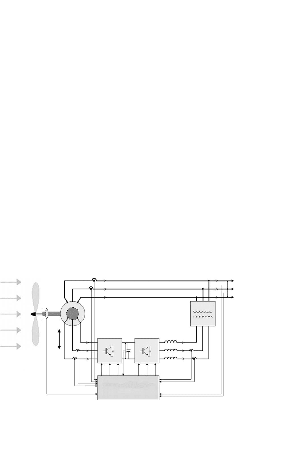
To take advantage of VSWTs, it is necessary to decouple
the rotor speed and the grid frequency. There are different
approaches to operate the VSWT within a certain opera-
tional range (cut-in and cut-out wind speed). One of the
approaches is dynamic slip control, where the slip is allowed
to vary upto 10% [55]. In these cases, doubly-fed induc-
tion generators (DFIG) are used (Fig. 27.56). One limitation
is that DFIG require reactive power to operate. As it is