Power electronic handbook
Подождите немного. Документ загружается.

754 J. M. Carrasco et al.
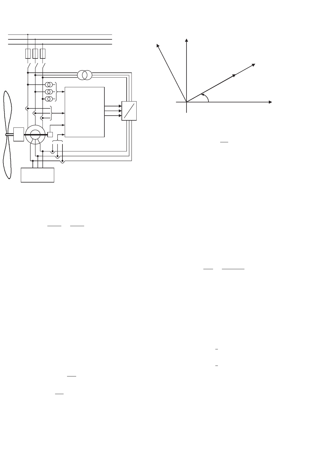
Fuses
Transformer
CONTROL
CIRCUIT
AC
AC
ω
r
i
r
i
s
u
s
OVERVOLTAGE
PROTECTION
CIRCUIT
GB
FIGURE 29.28 Wind turbine control block.
The stator magnetizing current i
m
is defined as:
i
m
=
λ
S
n ·L
m
=
L
S
n ·L
m
·i
S
+i
r
(29.23)
Figure 29.28 shows the control block of a wound-rotor
induction machine. The wound-rotor induction machine is
controlled by the rotor using a power converter that controls
the rotor current i
r
by changing the rotor voltage u
r
. The con-
trol of the stator current via the rotor current makes sense only
if the converter power is kept lower than the rated power of
the machine. The AC stator voltage generates a rotating mag-
netic field with angular frequency ω
e
. Relative to the rotor, this
magnetic field rotates only with the angular slip frequency. The
frequency of voltages induced in the rotor is low, so voltages
of the power converter are low too. Active and reactive power
of the induction generator, or a certain percentage of them,
can be controlled by the rotor current.
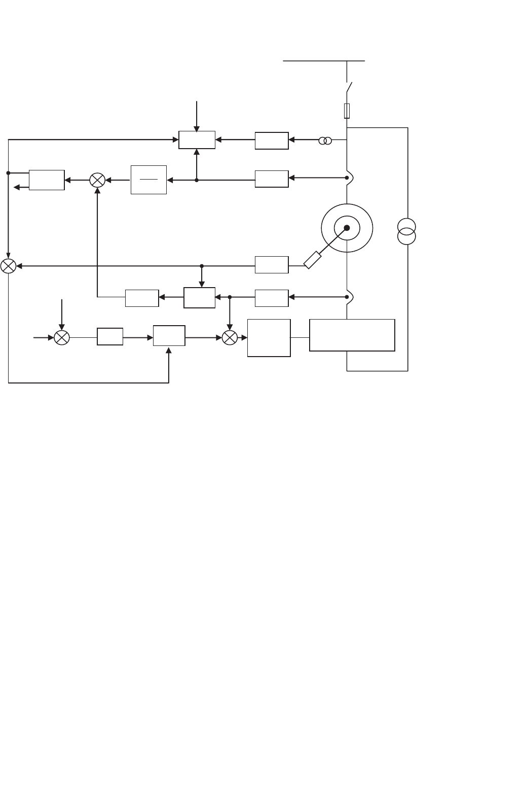
The machine model can be referred to the reference axes that
move with the magnetizing current. This system of coordinates
rotates with an angle θ
e
relative to the stator. In these axes
i
qm
= 0 as shown in Fig. 29.29.
Equations of the rotor and stator voltage become:
u
S
= R
S
·i
S
+
dλ
S
dt
+j · ω
e
·λ
S
(29.24)
u
r
= n
2
·R
r
·i
r
+
dλ
r
dt
+j ·
(
ω
e
−ω
r
)
·λ
r
(29.25)
i
m
q
s
d
e
θ
e
D
s
Q
s
FIGURE 29.29 Stator and rotor reference frames.
ω
e
=
dθ
e
dt
(29.26)
Supposing steady-state conditions and disregarding the
resistors in the stator and the rotor, because the voltage drop
is very low in comparison to the stator voltage, the stator and
rotor voltages can be determined as:
u
S
= jω
e
λ
S
(29.27)
u
r
= jω
s1
λ
r
(29.28)
The flux is determined from the stator voltage u
S
and
the angular frequency ω
e
of the AC system. Since both
are constant, the flux linkage and magnetizing current are
constant too.
i
m
=
λ
S
nL
m
=
u
ds
+ju
qs
jω
e
nL
m
(29.29)
As i
m
is constant, the stator current can be controlled at
any time, by means of controlling the rotor current that can
be deduced from Eq. (29.23). From Eq. (29.29) we can also
deduce that the direct component of the stator voltage u
ds
is
zero due to the quadrature component of the stator magne-
tizing current i
qm
is zero and so, the active and reactive power
can be obtained by the following equations:
P
S
=
3
2
u
ds
i
dsm
(29.30)
Q
S
=
3
2
u
qs
i
qsm
(29.31)
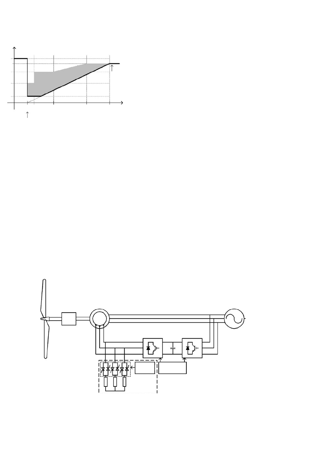
Figure 29.30 shows a block diagram of a vector control of
active and reactive power for a wound-rotor machine. Vector
control of cascaded doubly fed machine is presented in [21].
29 Wind Turbine Applications 755
P
S
,Q
S
3→2
3→2
n·L
m
L
S
1/s
3→2
e
jθ
r
1/n
PI
PWM
e
jθ
S1
PI
POWER
CONVERTER
P
S
,Q
S
P
S
,Q
S
+
+
−
+
−
θ
SL
P
S
ref
,Q
S
ref
θ
r
ENCODER
i
m
i
S
u
S
−
I
m
i
r
ref
RECT. /
POLAR
θ
e
+
+
FIGURE 29.30 Power control diagram of the wound-rotor machine.
29.2.4 Grid Connection Standards for Wind
Farms
29.2.4.1 Voltage Dip Ride-through Capability of
Wind Turbines
As wind capacity increases, network operators have to ensure
that consumer power quality is not compromised. To enable
large-scale application of wind energy without compromis-
ing power system stability, the turbines should stay connected
and contribute to the grid in case of a disturbance such as a
voltage dip. Wind farms should generate similar to conven-
tional power plants supplying active and reactive power for
frequency and voltage recovery, immediately after the fault
has been produced.
Thus, several utilities have introduced special grid connec-
tion codes for wind farm developers, covering reactive power
control, frequency response, and fault ride-through, especially
in places where wind turbines provide for a significant part of
the total power. Examples are Spain [22], Denmark [23], and
part of Northern Germany [24].
The correct interpretation of these codes is crucial for wind
farm developers, manufacturers, and network operators. They
define the operational boundary of a wind turbine connected
to the network in terms of frequency range, voltage tolerance,
power factor, and fault ride-through. Among all these require-
ments, fault ride-through is regarded as the main challenge
to the wind turbine manufacturers. Though the definition of
fault ride-through varies, the E.ON (German Transmission
and Distribution Utility) regulation is likely to set the stan-
dard [24]. This stipulates that a wind turbine should remain
stable and connected during the fault, while voltage at the
point of connection drops to 15% of nominal (i.e. a drop of
85%) for a period of 150 ms: see Fig. 29.31.
Only when the grid voltage drops below the curve, the
turbine is allowed to disconnect from the grid. When the
voltage is in the shaded area, the turbine should also sup-
ply reactive power to the grid in order to support grid voltage
restoration.
A major drawback of variable-speed wind turbines, espe-
cially for turbines with doubly fed induction generators
(DFIGs), is their operation during grid faults [25, 26]. Faults
in the power system, even far away from the location of
the turbine, can cause a voltage dip at the connection point
of the wind turbine. The dip in the grid voltage will result
in an increase of the current in the stator windings of the
DFIG. Because of the magnetic coupling between the stator
756 J. M. Carrasco et al.
Line-to-line voltage
U/U
N
100%
70%
45%
15%
0 150
Time fault occured
700 1500 3000 Time in ms
Lower value
of the
voltage band
FIGURE 29.31 E. On Netz requirements for wind farm behavior during
faults.
and rotor, this current will also flow in the rotor circuit and
the power electronic converter. This can lead to the permanent
damage of the converter. It is possible to try to limit the current
by current-control on the rotor side of the converter; however,
this will lead to high voltages at the converter terminals, which
might also lead to the destruction of the converter. A possible
solution that is sometimes used is to short-circuit the rotor
windings of the generator with the so-called crowbars.
The key of the protection technique is to limit the high
currents and to provide a bypass for it in the rotor circuit
via a set of resistors that are connected to the rotor wind-
ings (Fig. 29.32). This should be done without disconnecting
the converter from the rotor or from the grid. Thyristors can
be used to connect the resistors to the rotor circuit. Because
the generator and converter stay connected, the synchronism
of operation remains established during and after the fault.
Generator
gear
box
ASM
By-pass
resistors
Thyristors
Control Control
Converters
Grid
FIGURE 29.32 DFIG bypass resistors in the rotor circuit.
The impedance of the bypass resistors is of importance but
not critical. They should be sufficiently low to avoid excess
voltage on the converter terminals. On the other hand, they
should be high enough to limit the current. A range of values
can be found that satisfies both conditions. When the fault in
the grid is cleared, the wind turbine is still connected to the
grid. The resistors can be disconnected by inhibiting the gating
signals and the generator resumes normal operation.
29.2.4.2 Power Quality Requirements
for Grid-connected Wind Turbines
The grid interaction and grid impact of wind turbines has been
focused in the past few years. The reason behind this interest is
that wind turbines are among utilities considered to be poten-
tial sources of bad power quality. Measurements show that
the power quality impact of wind turbines has been improved
in recent years. Especially variable-speed wind turbines have
some advantages concerning flicker. But a new problem is
faced with variable-speed wind turbines. Modern forced-
commutated inverters used in variable-speed wind turbines
produce not only harmonics but also inter-harmonics.
The IEC initiated the standardization on power quality for
wind turbines in 1995 as a part of the wind turbine standard-
ization in TC88. In 1998, the IEC issued a draft IEC-61400-21
standard for “Power Quality Requirements for Grid Connected
Wind Turbines” [27]. The methodology of that IEC stan-
dard consists on three analyses. The first one is the flicker
analysis. IEC-61400-21 specifies a method that uses current
and voltage time series measured at the wind turbine terminals
to simulate the voltage fluctuations on a fictitious grid with
no source of voltage fluctuations other than the wind turbine
switching operation. The second one is switching operations.
29 Wind Turbine Applications 757
Voltage and current transients are measured during the switch-
ing operations of the wind turbine (start-up at cut wind speed
and start-up at rated wind speed). The last one is the harmonic
analysis which is carried out by the fast fourier transform (FFT)
algorithm. Rectangular windows of eight cycles of fundamen-
tal frequency width, with no gap and no overlapping between
successive windows are applied. Furthermore, the current total
harmonic distortion (THD) is calculated up to 50th harmonic
order [28, 29].
Recently, high frequency harmonics and inter-harmonics
are treated in the IEC 61000-4-7 and IEC 61000-3-6 [30, 31].
The methods for summing harmonics and inter-harmonics in
the IECE61000-3-6 are applicable to wind turbines. In order
to obtain a correct magnitude of the frequency components,
the use of a well-defined window width, according to the IEC
61000-4-7, Amendment 1 is of a great importance, as it has
been reported in ref. [32]
Wind turbines not only produce harmonics, they also
produce inter-harmonics, i.e. harmonics which are not a mul-
tiple of 50 Hz. Since the switching frequency of the inverter
is not constant but varies, the harmonics will also vary.
Consequently, since the switching frequency is arbitrary, the
harmonics are also arbitrary. Sometimes they are a multiple of
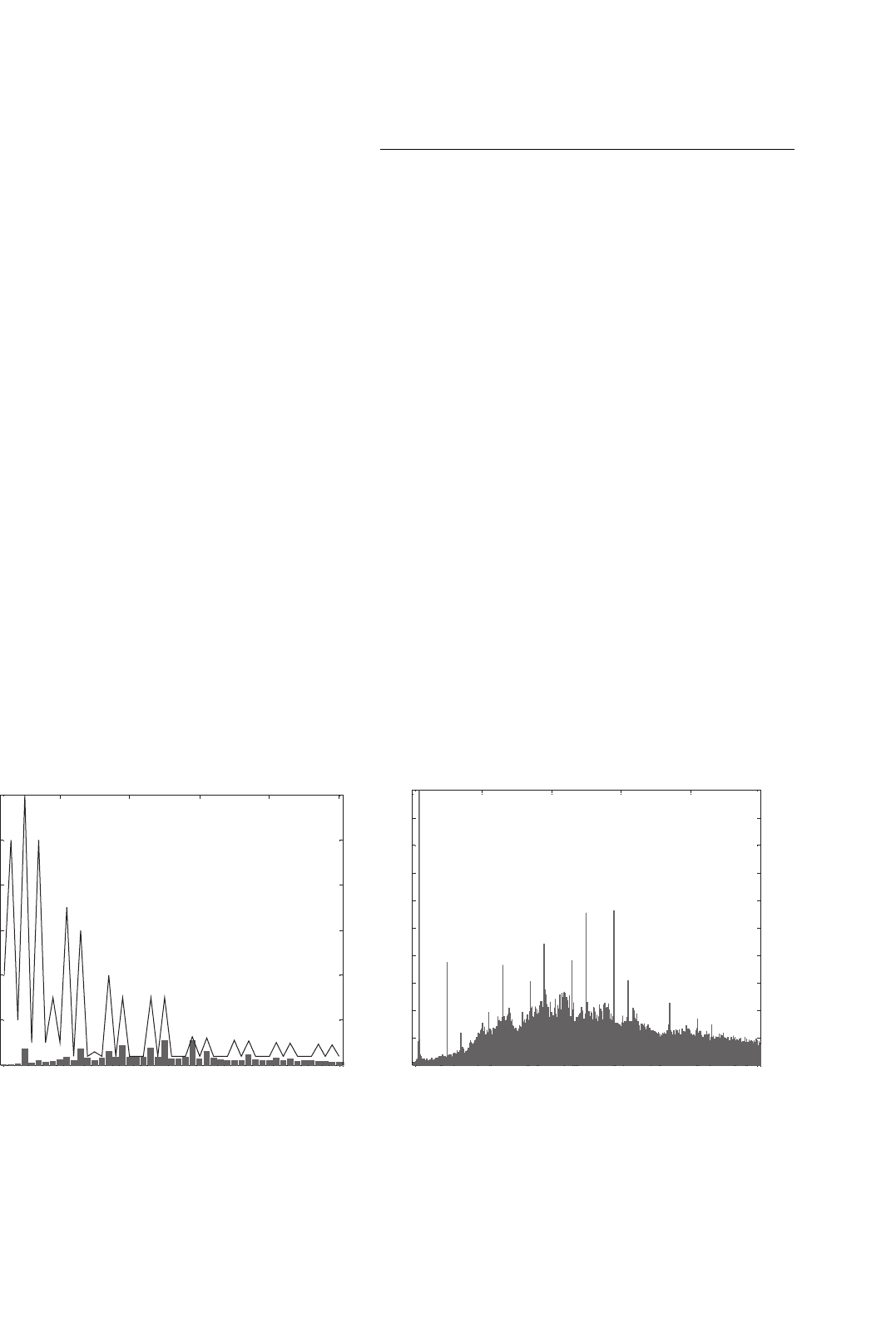
50 Hz and sometimes they are not. Figure 29.33 shows the total
harmonics spectrum from a variable-speed wind turbine. As
can be seen in the figure, at lower frequencies there are only
pure harmonics but at higher frequencies there are a whole
range of harmonics and inter-harmonics. This whole range of
harmonics and inter-harmonics represents variations in the
switching frequency of that wind turbine.
10 20 30 40 50
0
1
2
3
4
5
6
Harmonic order
Relative value to fundamental (%)
0 500 1000 1500 2000 2500
0
50
100
150
200
250
300
350
400
450
500
Frequency (Hz)
Amplitude (V)
(a) (b)
FIGURE 29.33 Typical results of a variable-speed wind turbine with a synchronous generator and full converter. (a) Harmonic content and the
comparison with the maximum level of IEC 1000-3-6 standard and (b) harmonic and inter-harmonic content in voltage.
29.3 Multilevel Converter for Very High
Power Wind Turbines
29.3.1 Multilevel Topologies
In 1980s, power electronics concerns were focused on the
increase of the power converters by increasing the voltage or
current to fulfill the requirements of the emerging applications.
There were technological drawbacks, that endure nowadays,
which make impossible to increase the voltage or current in the
individual power devices, so researchers were developing new
topologies based on series and parallel association of individual
power devices in order to manage higher levels of current and
voltage, respectively. Due to the higher number of individ-
ual power devices on such topologies it is possible to obtain
more than the classical two levels of voltage at the output
of the converter hence the multilevel denomination for this
converter.
29.3.2 Diode Clamp Converter (DCC)
In 1981, Nabae et al. presented a new neutral-point-clamped
PWM inverter (NPC-PWM) [33]. This converter was based
on a modification of the two-level converter topology. In the
two-level case, each power switch must support at the most a
voltage equal to DC-link total voltage so the switches should
be dimensioned to support such voltage.
The proposed modification adds two new switches and two
clamp diodes in each phase. In this converter each transistor
support at the most a half of the total DC-link voltage; hence,
758 J. M. Carrasco et al.
if the used power devices have the same characteristics of
those used in the two-level case, the DC-link can be doubled
and hence, the power which the converter can manage.
Figure 29.34 shows one phase of a three-level DCC with the
capacitors voltage divider and the additional switches and
diodes.
The analysis of the DCC converter states shows that there
are three different switching configurations. These possible
configurations are shown in Table 29.1.
When transistors S
3
and S
4
are switched on, the phase is
connected to the lowest voltage in the DC-link. In the same
manner, when the transistors S
1
and S
2
are switched on, the
phase is connected to the highest voltage in the DC-link, and
when the transistors S
2
and S
3
are switched on, the phase
is connected to the mid DC-link voltage through one of the
transistors and clamping diodes.
V
DC
S
1
S
2
S
3
S
4
Phase
O
FIGURE 29.34 Three-level DCC.
TABLE 29.1 Switching configurations for the three-level DCC
State S
1
S
2
S
3
S
4
Phase-O voltage
0 Off Off On On −V
DC
/2
1 Off On On Off 0
2 On On Off Off V
DC
/2
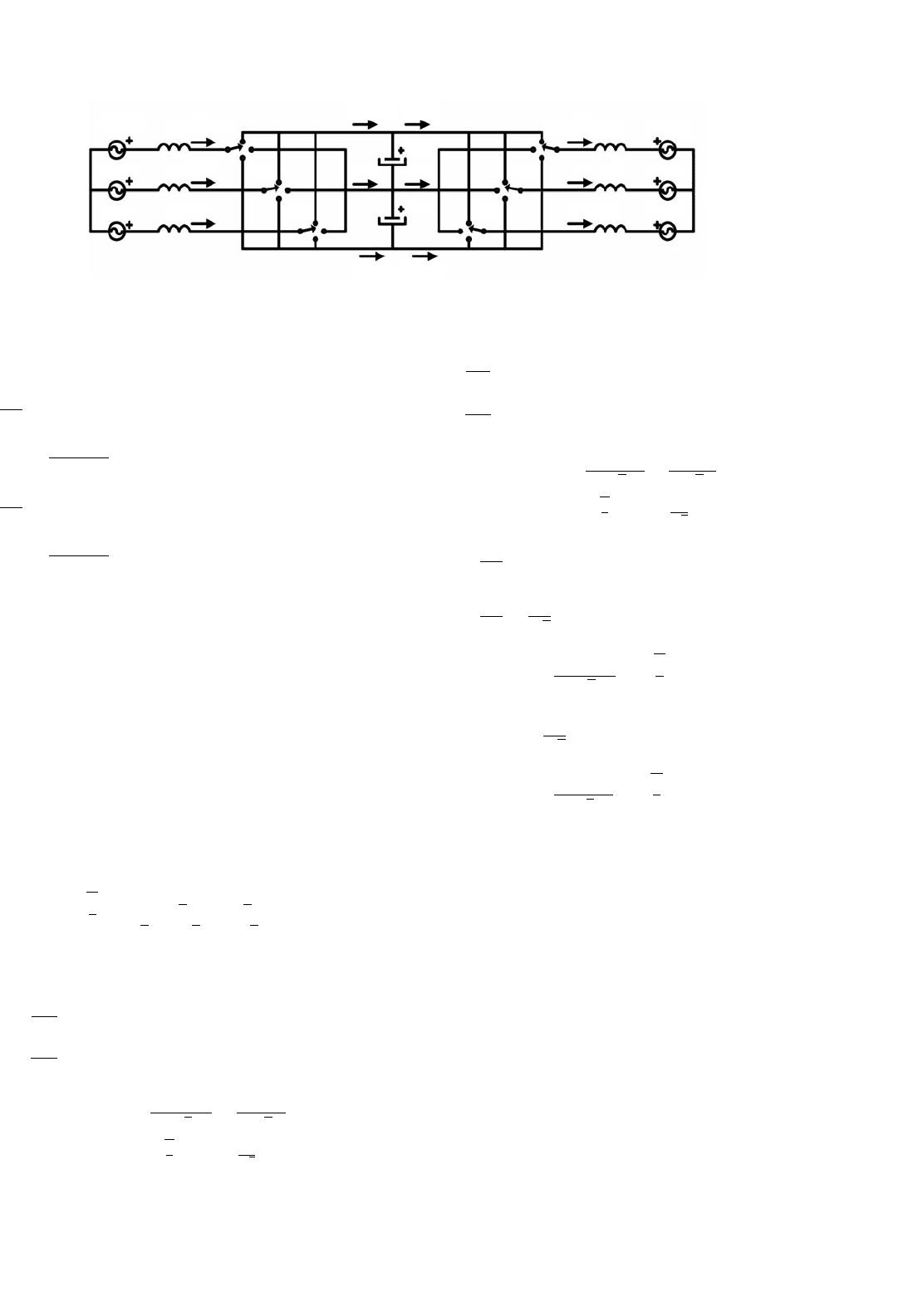
29.3.3 Full Converter for Wind Turbine Based on
Multilevel Topology
In order to decrease the cost per megawatt and to increase the
efficiency of the wind energy conversion, the nominal power
UTILITY
GRID
FIGURE 29.35 Diagram of a high power wind turbine with a full converter directly connected to the utility grid.
of wind turbines has been continuously growing in the last
years. The limitations of the two-level converters power ratings
versus three-level ones and the capacity of this to reduce the
harmonic distortion and electromagnetic interferences (EMI)
make the multilevel converters suitable for modern high power
wind turbine applications.
Figure 29.35 shows the diagram of high power wind tur-
bine directly connected to the utility grid, with a full converter
based on two coupled three-level DCC. The converter con-
nected to the generator acts like an AC–DC converter and its
main function is to extract the energy from the generator and
to deliver it to the DC-link. The converter connected to the
grid acts like a DC–AC converter and its main function is to
collect the energy at the DC-link and to deliver it to the utility
grid.
29.3.4 Modeling
The use of multilevel converters is limited by the following
drawbacks: typically very complex, control and voltage imbal-
ance problems at the DC-link capacitors. An analytical model
of the whole system is necessary to study this dynamic and
to develop control algorithms that meet with the design
specifications.
In [34], a general modeling strategy is proposed to obtain
the equations that describe the dynamics of the currents and
the capacitors voltages as functions of the control signals that
represent the voltage in each phase. Based on the nomenclature
that can be seen in Fig. 29.36, this modeling strategy yields
in the next mathematical model for the currents dynamics
Eqs. (29.32), (29.33):
v
sr1
v
sr2
v
sr3
= L
r
di
r1
/dt
di
r2
/dt
di
r3
/dt
+
1
3
2 −1 −1
−12−1
−1 −12
v
r1
v
r2
v
r3
(29.32)
v
si1
v
si2
v
si3
=−L
i
di
i1
/dt
di
i2
/dt
di
i3
/dt
+
1
3
2 −1 −1
−12−1
−1 −12
v
i1
v
i2
v
i3
(29.33)
29 Wind Turbine Applications 759
V
sr3
V
sr2
V
sr1
L
r
i
r3
v
r3
v
r2
v
r1
o
idcr1
i
dcr2
i
dcr3
i
dci3
i
dci2
idci1
V
c1
v
i1
v
i2
v
i3
L
i
i
i3
i
i2
i
i1
V
si1
V
si2
V
si3
L
i
L
i
V
c2
i
r2
i
r1
L
r
L
r
n
FIGURE 29.36 Nomenclature criterion for the modeling of the full DCC converter.
And the next ones for capacitors voltages dynamics Eq. (29.34):
2C
dx
1
dt
=
(
δ
r1
i
r1
+δ
r2
i
r2
+δ
r3
i
r3
)
−
(
δ
i1
i
i1
+δ
i2
i
i2
+δ
i3
i
i3
)
x
1
=
v
c1
+v
c2
2
2C
dx
2
dt
=
δ
2
r1
i
r1
+δ
2
r2
i
r2
+δ
2
r3
i
r3
−
δ
2
i1
i
i1
+δ
2
i2
i
i2
+δ
2
i3
i
i3
x
2
=
v
c2
−v
c1
2
(29.34)
where, x
1
and x
2
are chosen as variables to facilitate the con-
troller design and represent the dynamics of the sum and the
difference of the capacitors voltages, respectively.
As indicated in [34], it is useful to represent the system in
αβγ -coordinates because after the transformation appears the
γ control signal as a third freedom degree of the control, more-
over this transformation shows the direct relation between this
control signal and the capacitors voltage balance. To change
to the αβγ -coordinates, an invariant power transformation
has been used. The voltages and currents, which are vec-
tors originally in abc-coordinates, are transformed into αβγ -
coordinates according to the following matrix transformation
shown in Eq. (29.35):
T =
2
3
1 −1/2 −1/2
0
√
3/2 −
√
3/2
1/
√
21/
√
21/
√
2
(29.35)
The transformed equations are:
L
r
di
rα
dt
di
rβ
dt
=
v
srα
v
srβ
−x
1
δ
rα
δ
rβ
−x
2
δ
2
rα
−δ
2
rβ
√
6
+
2δ
rα
δ
rγ
√
3
−
2
3
δ
rα
δ
rβ
+
2
√
3
δ
rβ
δ
rγ
(29.36)
L
i
di
iα
dt
di
iβ
dt
=−
v
siα
v
siβ
+x
1
δ
iα
δ
iβ
+x
2
δ
2
iα
−δ
2
iβ
√
6
+
2δ
iα
δ
iγ
√
3
−
2
3
δ
iα
δ
iβ
+
2
√
3
δ
iβ
δ
iγ
(29.37)
2C
dx
1
dt
=
δ
rα
δ
rβ
i
rα
i
rβ
−
δ
iα
δ
iβ
i
iα
i
iβ
2C
dx
2
dt
=
2
√
3
δ
rα
δ
rβ
i
rα
i
rβ
δ
rγ
+
δ
2
rα
−δ
2
rβ
√
6
, −
2
3
δ
rα
δ
rβ
i
rα
i
rβ
···
−
2
√
3
δ
iα
δ
iβ
i
iα
i
iβ
δ
iγ
−
δ
2
iα
−δ
2
iβ
√
6
, −
2
3
δ
iα
δ
iβ
i
iα
i
iβ
(29.38)
In these final equations, it is important to point out the
relation between the γ control signal and the input and output
power of the DCC full converter.
29.3.5 Control
As it can be observed in Eqs. (29.36) and (29.37) the rectifier
and inverter currents i
r
αβ
, i
i
αβ
can be controlled separately due
to the decoupling of these equations. Also it can be seen in
Eq. (29.38) that the control objective on x
1
can be achieved
using the normalized voltage references δ
r
αβ
or δ
i
αβ
, and x
2
can be controlled using δ
r
γ
or δ
i
γ
. The implemented control
consists basically of independently controlling the inverter and
the rectifier. The inverter controls the voltage balance in the
DC-link, whereas the rectifier controls the active and reactive
power extracted from the generator.
760 J. M. Carrasco et al.
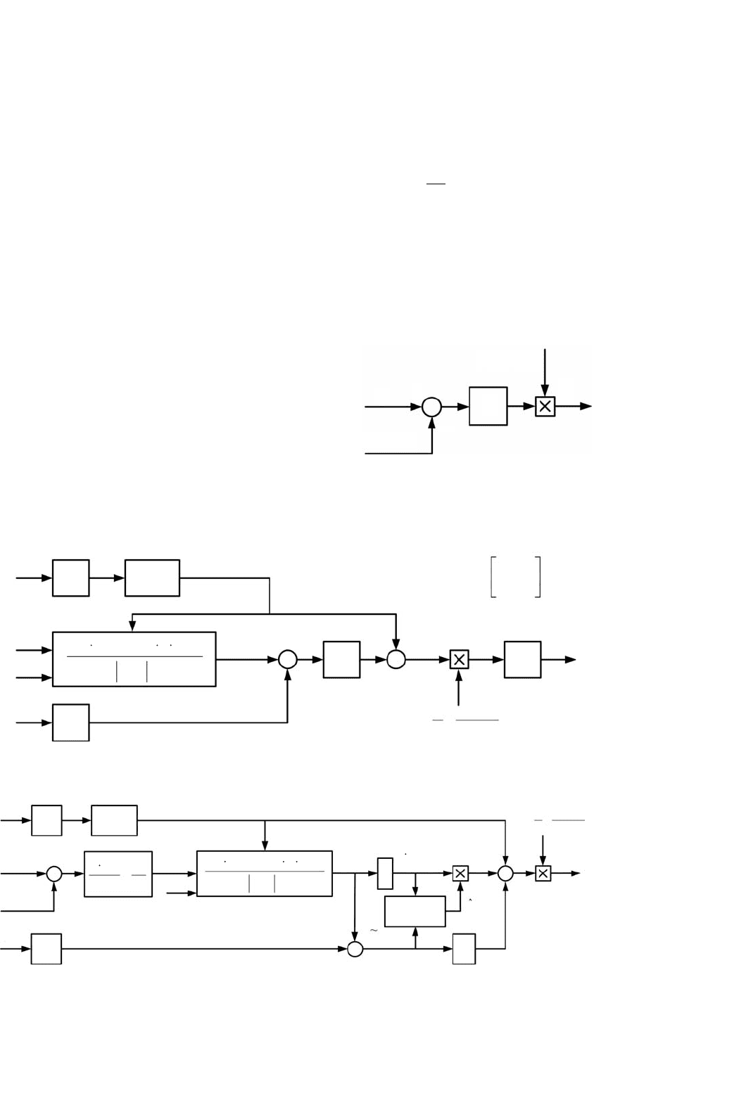
29.3.5.1 Rectifier Control
Figure 29.37 shows the control scheme proposed for the recti-
fier. The objective of this controller is to make the currents of
the generator such that the active and reactive power achieve
the reference ones.
It is necessary to notice that the rectifier γ component of
the normalized voltage is imposed to be equal to zero δ
r
γ
= 0
for not affecting on voltage balance, because this balancing is
implemented on the inverter control.
29.3.5.2 Inverter Control
Inverter control is divided in two parts. The first part controls
the sum of the capacitor voltages x
1
, while the second part
makes the difference between the capacitor voltages x
2
as small
as possible.
29.3.5.3 Sum of the Capacitor Voltages Control
The controller scheme, which can be seen in Fig. 29.38, has
been described before in [35], and it is appropriated for this
application due to the similarities found in the equations.
The main objective of the controller is to achieve a desired
value of the total DC-link voltage. Additionally, the controller
can take a reactive power reference to control the power factor
of the energy delivered to the utility grid.
V
r
abc
V
r
ab
V
r
ab, f
V
r
ab, f
V
r
ab, f
I
r
ab
I
r
abc
I
J =
r
ab, ref
I
r
ab
VJ
r
ab, f
P
r
ref
P
r
ref
V
r
ab, f
Q
r
ref
Q
r
ref
+
+
+
−
d
ab
r
d
abc
r
0
10
−1
50 Hz
Resonant
Filter
3/2
3/2
PI
2/3
12
x
1
v
c1
+v
c2
=
2
+
FIGURE 29.37 Control diagram of the rectifier.
V
i
ab, f
V
J
i
ab, f
V
i
ab, f
V
i
ab, f
V
i
ab
V
i
abc
x
ref
2
1
P
i
ref
V
i
ab, f
Q
i
ref
2
+
x
1
2
I
i
abc
I
i
ab
Q
i
ref
I
s
L
P
i
ab
I
i
ab
I
I
i
ab, ref
i
ab, ref
P
i
ref
aK
i
ssa+
+
K
p
50 Hz
Resonant
Filter
12
x
1
vc1+vc2
=
L estimator
3/2
3/2
+
+
+
+
−
d
i
ab
+
−
FIGURE 29.38 Inverter control scheme for the sum of the capacitors voltages.
29.3.5.4 Difference of the Capacitor Voltages Control
Avoiding the quadratic terms in δ from the equation of the
difference of the capacitor voltages in Eq. (29.38), expression
(29.39) is obtained:
dx
2
dt
= K · P
i
ref
·δ
i
γ
(29.39)
where K is a constant. With this equation, the following
control scheme (Fig. 29.39) is proposed:
The objective of the controller is to add a voltage reference
in γ direction that depends on the sign of the power and the
imbalance of the capacitors voltages.
ref = 0
+
−
x
2
sign(P
ref
)
PI
d
i
i
g
FIGURE 29.39 Proposed capacitors voltages balancing control.

29 Wind Turbine Applications 761
29.3.5.5 Modulation
Finally, the normalized voltage references δ
r
αβγ
and δ
i
αβγ
,
obtained from the whole controllers, are translated to
abc-coordinates and the 3D-space vector modulation
algorithm [36] is used to generate the duty cycles and the
switching times of power semiconductors.
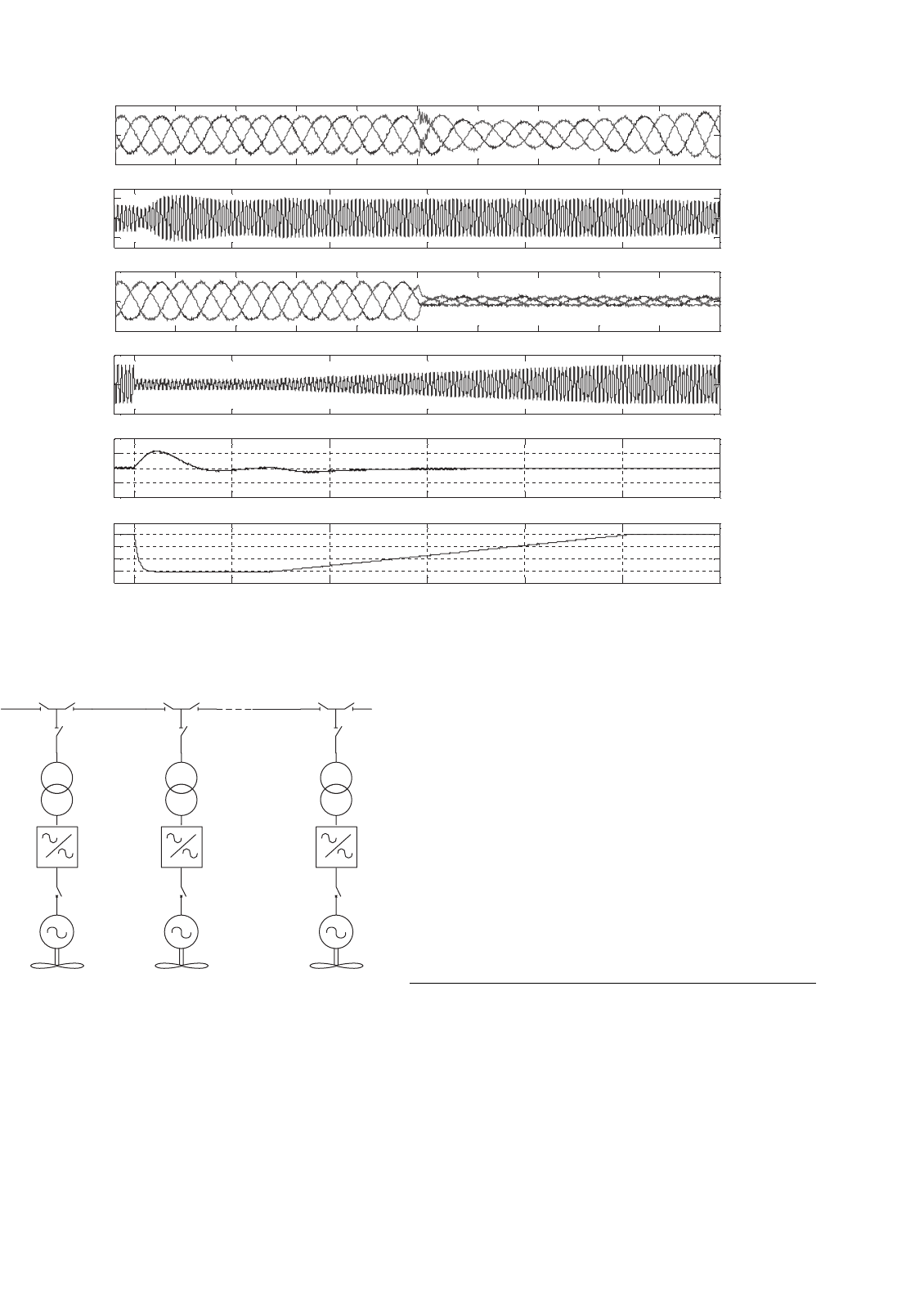
29.3.6 Application Example
As it was explained before, the standards on energy quality
related to renewable energy are focusing to request the plants
to contribute to the general stability of the electrical system. To
show that the exposed modeling strategy and control scheme
can be used to meet the design specification, the electrical sys-
tem of a wind turbine has been modeled. It consists of an
asynchronous induction motor connected to the utility grid
through a full DCC converter. The parameters of the exam-
ple are: nominal power: 3 MW, switching frequency: 2.5 kHz,
DC-link nominal voltage: 5 kV, and utility grid line voltage:
2.6 kV. The experiment consists of studying the behavior of
the system when there is a voltage dip in the utility grid due to
a short-circuit. Figure 29.40 shows the envelope of the voltage
dip that has been used to carry out the results.
Figure 29.41 shows the results obtained under the voltage
dip condition. Good behavior of the currents on both the
sides of the full DCC converter, DC-link voltage, and energy
extracted from the generator illustrates the suitability of the
control scheme and the model to study the system.
V(pu)
1
0.8
0.15
0 150 3000 Time (ms)
FIGURE 29.40 Voltage dip envelope.
29.4 Electrical System of a Wind Farm
29.4.1 Electrical Schematic of a Wind Farm
A wind farm is integrated by wind turbines and the substa-
tion that connect the farm to the utility grid to evacuate the
electrical energy. The wind farm is arranged by string of wind
turbines. Figure 29.42 shows a string compounded by several
aerogenerators. These wind turbines are connected by man-
ual switch breakers which isolate a wind turbine or it isolates
the whole string. In variable-speed applications, an AC/AC
power converter is used. This power converter is connected by
a manual switch to the machine. The power converter includes
a remote controlled switch breaker which isolates from the
power transformer. The switch breaker is used for automatic
reconnection after a fault. Figure 29.42 shows the transformer
connection.
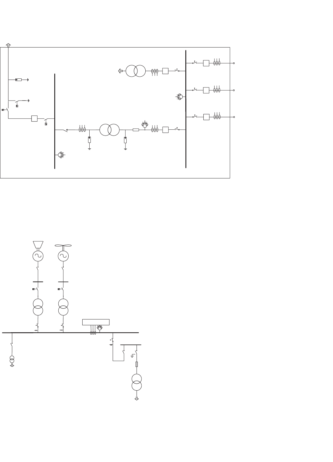
A schematic diagram of a typical substation is shown in
Fig. 29.43. A large transformer, depicted in the figure, or
several transformer connected in parallel, changes from the
medium voltage to a higher voltage level. A typical volt-
age levels in Europe could be 20 kV/320 kV. The substation
also incorporates bus bar, protections systems, measurement
instrumentation, and auxiliary services circuit. Bus bar voltage
measurement is made by voltage transformer. Each branch
current, including several wind turbines, is measured by
current transformer.
Some farms with lower rated power or connected to an
isolated grid, e.g. wind-diesel systems, do not use this large
transformer. The schematic of an isolated wind-diesel instal-
lation is represented in Fig. 29.44. Every power generator and
load are connected to a medium voltage bus bar, in the typical
range of 10–20 kV. The transformers are protected by circuit
breakers that connect the lines directly to ground when open.
A measurement system is used for power consumption and
electrical quality control. Also auxiliaries’ power supply feeds
the substation equipment.
29.4.2 Protection System
Protection of wind power systems requires an understanding
of system faults and their detection, as well as their safe dis-
connection. The protection system of a wind farm is mainly
included in the substation. Circuit breaker and switchgear [37]
are extensively used for overcurrent protection. New type of
relay has been designed for the protection of wind farms
that incorporate fixed-speed induction generators as described
in [38]. A protection relay can be installed in the medium-
voltage collecting line at the common point connection to the
utility grid. This relay provides short-circuit protection for the
collecting line and the medium-voltage (MV) and low-voltage
(LV) circuits. Consequently, the relay allows wind farms to
be constructed and adequately protected without the need to
include fuses on the MV side of each generator–transformer.
The variable speed generator also includes digital relay pro-
tection and can be programmed for complex coordination and
selectivity. This modern protection system can be used for
voltage gap or sag function protection. Moreover, they can
implement modern stabilization programs [39].
762 J. M. Carrasco et al.
1.9 1.92 1.94 1.96 1.98 2 2.02 2.04 2.06 2.08 2.1
−1000
0
1000
Current (A)
(a)
2 2.5 3 3.5 4 4.5 5
−1000
0
1000
Current (A)
(b)
1.9 1.92 1.94 1.96 1.98 2 2.02 2.04 2.06 2.08 2.1
−1000
0
1000
Current (A)
(c)
2 2.5 3 3.5 4 4.5 5
−1000
0
1000
Current (A)
(d)
2 2.5 3 3.5 4 4.5 5
4.5
5
5.5
Voltage (kV)
(e)
2 2.5 3 3.5 4 4.5 5
0
1
2
Time (s)
Power (kW)
(f)
FIGURE 29.41 Response of the system to a voltage dip: (a) inverter side currents (detail); (b) inverter one phase current; (c) rectifier side currents
(detail); (d) rectifier one phase current; (e) DC-link voltage; and (f) active power extracted from the generator.
FIGURE 29.42 Typical branch composed by several wind turbines.
29.4.3 Electrical System Safety: Hazards and
Safeguards
It is important to understand the hazards of electricity at the
power system supply level. The safety of wind farm includes a
good knowledge of electrical blast, electrocution, short circuits,
overloads, ground faults, fires, lifting and pinching injuries.
It is also recommended to review the principles, governmental
regulations, work practices, and specialized equipment relat-
ing to electrical safety. Installers and maintenance personnel
have to know the different types of “Personal Protective Equip-
ment” through demonstrations of locking and tagging devices,
protective clothing, and specialized equipment. The isolation
and “Lockout Practices Procedures” for the lockout and iso-
lation of electrical equipment can also be implemented into
the existing site regulations and policies. A common practise
is to use isolation transformer and grounding circuit breaker
as they are being operated.
29.5 Future Trends
Future trends relating to power electronics used in wind
turbine applications can be summarized in the following
points:
29.5.1 Semiconductors
Improvements in the performance of power electronics vari-
able frequency drives for wind turbine applications have been
directly related to the availability of power semiconductor
29 Wind Turbine Applications 763
BUS BAR HV BUS BAR HV
L1
L2
L3
MAIN POWER
GRID
WIND POWER
GENERATORS
Current
measurement
Voltage
measurement
Auxiliary
Service
FIGURE 29.43 Schematic diagram of a typical wind farm substation.
Auxiliary
Service
Measurement
WIND
GEN
DIESEL
GEN
Switch gear
LOAD
FIGURE 29.44 Schematic diagram of a wind–diesel generation system.
devices with better electrical characteristics and lower prices
because the device performance determines the size, weight,
and cost of the entire power electronics used as interfaces in
wind turbines [8, 18, 9].
The thyristor is the component that started power
electronics. It is an old device with decreasing use in medium
power applications, which was replaced by turn-off compo-
nents like insulated gate bipolar transistor (IGBTs). The IGBT,
which can be considered as an MOS bipolar Darlington, is now
the main component for power electronics, and also for wind
turbine applications. They are now mature technology turn-
on components adapted to very high power (6 kV–1.2 kA), and
they are in competition with gate turn-off thyristor (GTO) for
high power applications [40].
Recently, the integrated gated control thyristor (IGCT) has
been developed, consisting of the mechanical integration of
a GTO plus a delicate hard drive circuit that transforms the
GTO into a modern high performance component with a large
safe operation area (SOA), lower switching losses, and a short
storage time [41–43].
The comparison between IGCT and IGBT for frequency
converters, used especially in wind turbines is explained below:
•
IGBTs have higher switching frequency than IGCTs so
they introduced less distortion in the grid. Accordingly
if we use two three-phase systems in parallel, it is possi-
ble to double the resulting switching frequency without
increasing the power loss, hence it is possible to have a
total harmonic distortion (THD) of less than 2% without
special harmonic filters.