Power electronic handbook
Подождите немного. Документ загружается.

31 Flexible AC Transmission Systems 805
Th
2
Th
1
L
C
CONTROL
CIRCUIT
V
Ref
C
C
FIGURE 31.14 6-Pulse SVC.
AC
Line
Th
11
Th
21
Th
1n
Th
2n
C
1
i
C
n
FIGURE 31.15 Thyristor-switched series capacitors.
total number of capacitors is three, they could have values
proportional to 1, 2, and 3. Therefore, by combining these
values it is possible to obtain equivalent capacitor proportional
to 1, 2, 3, 4, 5, and 6.
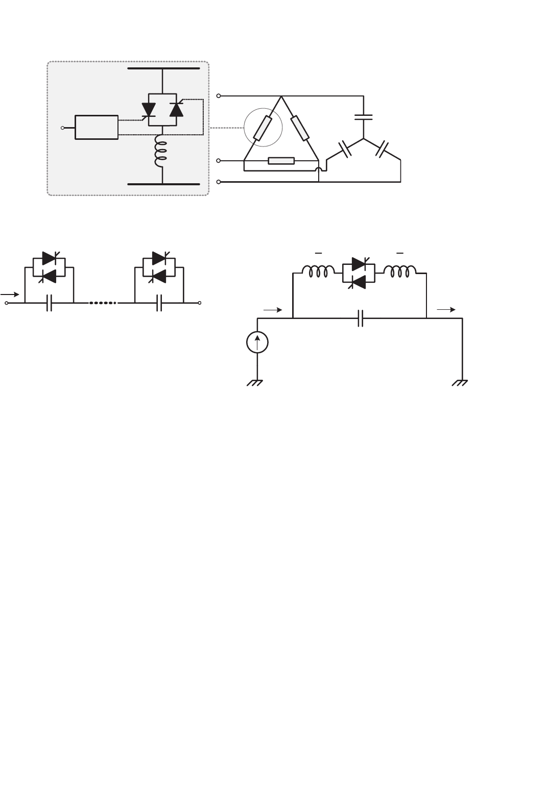
31.4.1.5 Thyristor-controlled Series Capacitor (TCSC)
Figure 31.16 shows the thyristor-controlled series capacitor
(TCSC). In this figure, the transmission line and the voltage
sources in its ends are represented by a current source because
this is the actual behavior of most of the transmission system.
This compensator is also based on the TCR which was first
developed for shunt connection. When the TCR is used con-
nected in series with the line, it has to be always connected in
parallel with a capacitor because it is not possible to control
the current if the equivalent of the transmission line and the
sources is a current source. This circuit is similar to the con-
ventional SVC, with the difference that the TCSC is connected
in series with the line. In this compensator, the equivalent
value of the series connected reactor can be continuously con-
trolled by adjusting the firing-angle of the thyristors. As a
consequence, this device presents a continuously controllable
series capacitor. Various practical system based on this con-
cept is under operation around the world [12–14]. This device
has been used for power flow control and power oscillation
damping.
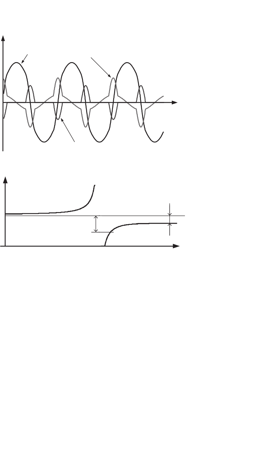
Figure 31.17 presents the current and voltage waveforms
in the TCSC, showing that although there is a large amount
Th
11
Th
21
C
i
L
2
L
2
i
FIGURE 31.16 Thyristor-controlled series capacitors.
of harmonics in the capacitor and reactor currents, capacitor
voltage is somehow almost sinusoidal. In actual applications,
these harmonics are not a serious concern and they are filtered
by the capacitor itself and the transmission line impedance.
Figure 31.18 shows the equivalent impedance of the TCSC
as a function of the firing-angle α. This figure shows that this
device has both capacitive and inductive characteristic regions.
It also has a resonance for α around 145
◦
, in this example.
In normal operation, the TCSC is controlled in the capacitive
compensation region where its impedance varies from its min-
imum value Z
min
for firing-angle α =180
◦
and its maximum
safe value Z
max
for α around 150
◦
. Operation with α close to
the resonance region is not safe. This device can operate also
in the inductive region, but in this case, normally it is used
only with α = 90
◦
to decrease power transfer capability of the
transmission line.
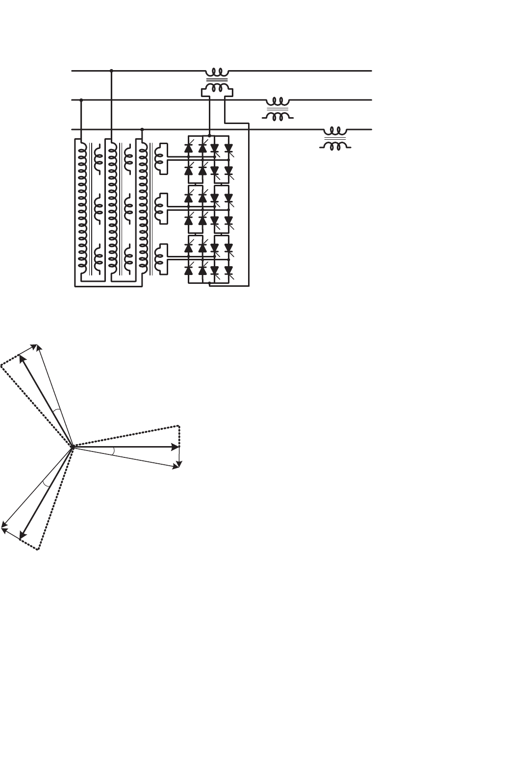
31.4.1.6 Thyristor-controlled Phase Angle Regulator
The thyristor-controlled phase angle regulator (TCPAR),
shown in Fig. 31.19 as an example, may improve considerably
the controllability of a utility power transmission system.
In this figure, only control of phase “a” is detailed. The series
806 E. H. Watanabe et al.
Reactor current
Capacitor current
Capacitor voltage
t
FIGURE 31.17 TCSC voltage and current waveforms.
100° 110° 120° 130° 140° 150° 160° 170° 180°
0
Firing angle, α
inductive
capacitive
Z
max
Z
min
Equivalent Impedance
90°
FIGURE 31.18 TCSC equivalent reactance.
voltage generated in phase “a” comes from three secondary
windings of a transformer whose primary side is connected
between phases “b” and “c.” Each of the three secondary
windings can be connected in series with the line through
the thyristors switching. The thyristors are connected in anti-
parallel, forming bidirectional naturally commutated switches.
By turning on a set of thyristors, a voltage whose magni-
tude can be controlled by phase control is connected in series
with the transmission line. The number of secondary wind-
ings is chosen as to decrease harmonic content of the series
compensation voltage.
The TCPAR in Fig. 31.19 has some peculiarities that should
be pointed out. One of them is that active power can only
flow from the shunt to the series windings – therefore reverse
power flow is not possible. The compensation voltage phasor,
as shown in Fig. 31.20, has a limited range of variation: in
the case of phase “a,” its locus is along a line orthogonal to
V
a
, because the injected voltage is in phase with the voltage
(V
b
− V
c
). As a consequence, it is not possible for the TCPAR
to generate a compensating voltage phasor whose locus is a
circle, as shown in Fig. 31.7, for the case of an ideal generic
series compensator.
Other configuration of phase-shifters can be found in the
literature, e.g. [15, 16].
31.4.2 FACTS Devices Based on
Self-commutated Switches
There are various different types of FACTS devices based on
self-commutated switches and the names used here are in
accordance with the names published in [9]. Some of them
are newer devices and are not in that reference. In this case,
the name used is as it appears in the literature. In [2] it is
possible to find most of the details of FACTS devices.
31 Flexible AC Transmission Systems 807
V
a
a
b
c
V
a
’
FIGURE 31.19 Thyristor-controlled phase angle regulator (TCPAR).
α
V
a
α
α
V
b
V
c
V
a
’
V
b
’
V
c
’
FIGURE 31.20 Phasor diagram of the TCPAR in Fig. 31.19.
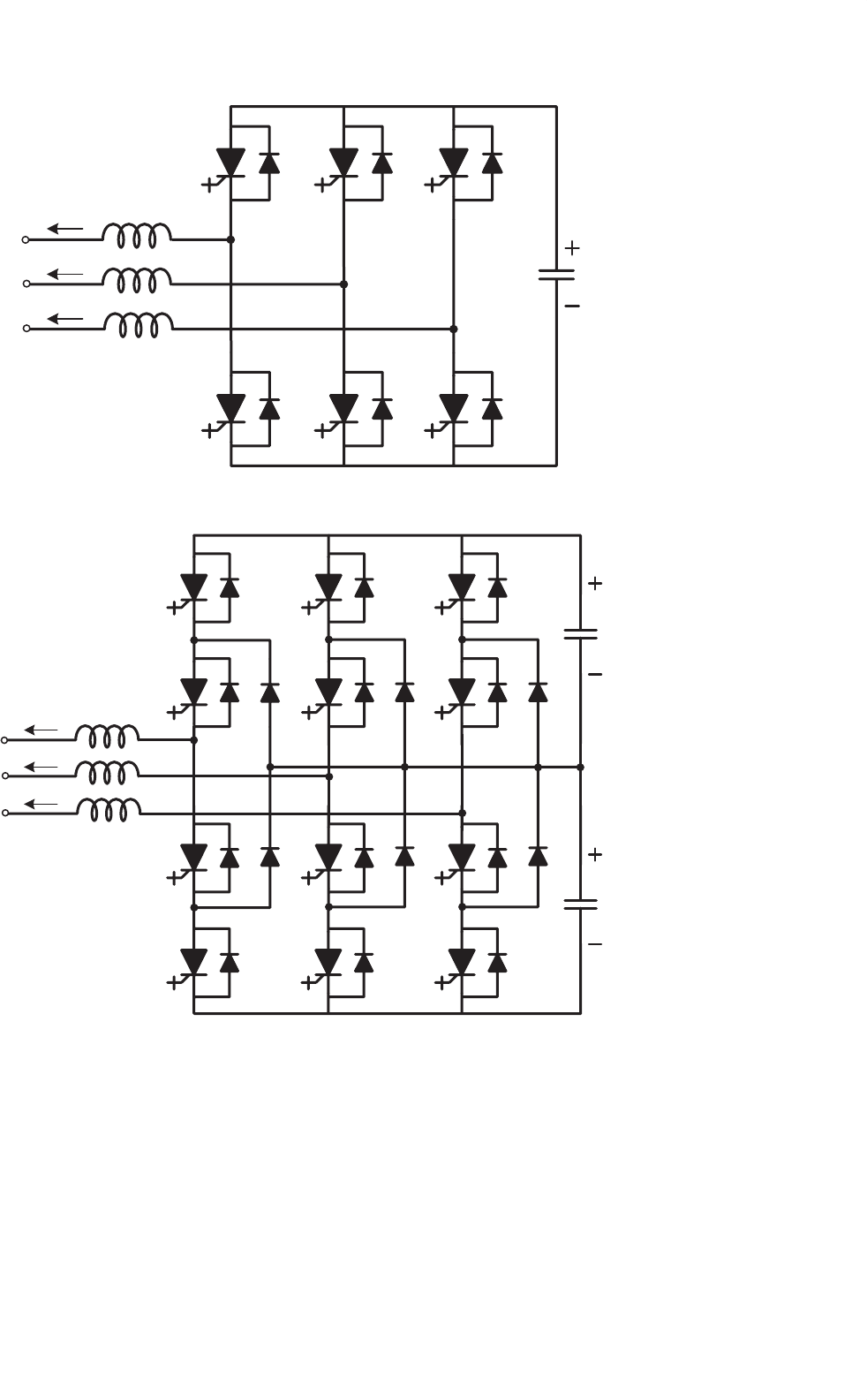
31.4.2.1 The Static Synchronous Compensator
The development of high-power self-commutated devices like
GTOs, IGBTs, and IGCTs has led to the development of high-
power voltage source inverters (VSI), as the 6-pulse 2-level
VSI shown in Fig. 31.21a [4] or the 3-level neutral point
clamped VSI shown in Fig. 31.21b [17]. In the figure, the
switches are GTOs (they could be IGBTs, IGCTs, or other self-
commutating switches) with an anti-parallel-connected diode,
which operates with a unidirectional voltage blocking capabil-
ity and a bidirectional current flow. In contrast, the current
source inverters (CSI) used in HVDC transmission systems
use switches (thyristors) operating with unidirectional current
flow and bidirectional voltage blocking capabilities.
In a conventional VSI, for industrial applications, a voltage
source is connected at the inverter DC side. However, in the
case that only reactive power has to be controlled, the DC
voltage source may be replaced by a small capacitor. If active
power has to be absorbed or generated by the compensator,
an energy storage system has to be connected at the DC side
of the VSI.
In practical applications, small reactors (L) are necessary to
connect the VSI to the AC network. This is necessary to avoid
currents peaks during switching transients. In most cases, these
small reactors are just the leakage inductance of the coupling
transformers.
The first high rating STATCOM is under operation since
1991 [18] in Japan and uses three single-phase VSI to form
one 3-phase, 6-pulses, 10 MVA converter. To guarantee low
losses, the switching frequency is equal to the line frequency
and a total of eight sets of 3-phase converters are used to
form a 48-pulse converter. All the converters have a common
DC capacitor in their DC side. In the AC side, the convert-
ers are connected in series through a zigzag transformer to
eliminate low frequency voltage harmonics. The device, whose
compensation capability is 80 MVA, was developed to increase
the transient stability margin of a transmission line and has
allowed a 20% increase of the transmitted power above the
previous stability limit. Since it was developed for improving
808 E. H. Watanabe et al.
G
1
G
3
G
5
G
6
G
2
G
4
D
4
D
6
D
2
D
1
D
3
D
5
a
b
c
V
d
C
d
L
G
1
G
3
G
5
G
6
G
2
G
4
D
4
D
6
D
2
D
1
D
3
D
5
V
d
C
d
v
a
v
b
v
c
v
a
v
b
v
c
i
a
i
c
i
b
i
a
i
c
i
b
a
b
c
L
G
7
G
9
G
11
G
12
G
8
G
10
D
10
D
12
D
8
D
7
D
9
D
11
V
d
C
d
0
(a)
(b)
FIGURE 31.21 (a) Basic 6-pulse VSI 2-level var compensator and (b) basic 3-level var compensator.
transient stability margin, it normally operates in standby
mode, without reactive compensation and, consequently, low
losses. During transient situation, this STATCOM operates for
a short time until the system is stable.
The development of a ±100 Mvar STATCOM, in USA, was
reported in [19]. It is based on eight sets of 3-phase bridge
converters, similar to that shown in Fig. 31.21b and was devel-
oped for reactive power control, so it can operate continuously
with acceptable losses. The switching frequency is equal to line
frequency and the number of pulses is 48 and, therefore, the
output voltage waveform is almost sinusoidal and harmonic
filters are not used in both cases referred in [18] and [19].

31 Flexible AC Transmission Systems 809
31.4.2.1.1 Basic Switching Control Techniques In FACTS
applications the power ratings of the converters are in the
range of some MW to hundreds of MW and the switching
frequency is lower, if compared to the switching frequency
used in industrial application converters, to avoid excessive
switching losses. However, there are various switching control
types, being the most known so far:
– Multi-pulse converters switched at line frequency, as in
[18] and [19];
– Pulse width modulation (PWM) with harmonic elimina-
tion technique [20];
– Sinusoidal PWM [6];
– Cascade converters [21].
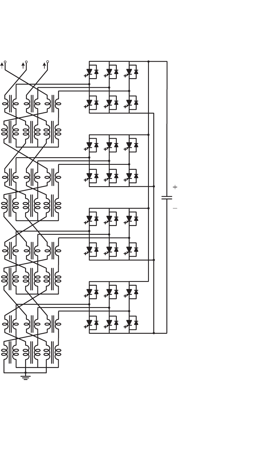
31.4.2.1.2 Multi-pulse Converters Switched at Line Frequency
The multi-pulse converter was the first choice for STATCOM
application as it presents low losses and low harmonic con-
tent [18, 19]. Figure 31.22 shows a 24-pulse converter based
on 3-phase, 2-level 6-pulse converters. In this case, the zigzag
transformers are connected in such a way as to produce phase
differences of 15, 30, 45, and 60
◦
. With this arrangement,
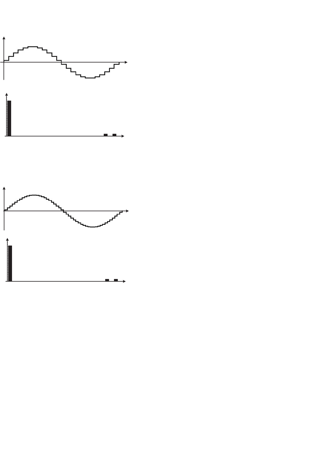
the resulting output voltage and its harmonic spectrum are
as shown in Fig. 31.23. The first two harmonics components
are the 23rd and 25th order harmonics. Figure 31.24 shows
the voltage waveform for a 48-pulse converter and its respec-
tive harmonic spectrum. In this case, the first two harmonic
components are the 47th and 49th order harmonics. The total
harmonic distortion (THD) for the 24- and 48-pulse convert-
ers are 7 and 3.3%, respectively. These converters can also be
built by using 3-level converters. However, one drawback of
the multi-pulse converter is the complexity of the transform-
ers, which have to operate with high harmonic content in their
voltage as well as various different turns ratio.
31.4.2.1.3 PWM (Pulse Width Modulation) with Harmonic
Elimination Technique One way to avoid the complexity
of the multi-pulse converters is to use PWM with harmonic
elimination technique [20]. With this approach, it is possible
to use relatively low switching frequency and, consequently,
have low switching losses. The PWM modulation is obtained
by offline calculation of the switches “on” and “off” instants
in such a way as to eliminate the low frequency harmonics.
Figure 31.25a shows an example of voltage waveform with
“on” and “off” instants calculated in such a way as to elim-
inate the 5th, 7th, 11th, 13th order harmonics. This voltage
corresponds to the voltage between one phase of the con-
verter and the negative terminal of the DC side. Figure 31.25b
shows the control angle as a function of the modulation index
m
a
. Figure 31.26 shows the harmonic spectrum for the phase-
to-phase voltage waveform corresponding to that shown in
Fig. 31.25a. Here it is considered that the RMS value of the
fundamental component of the voltage in Fig. 31.25 is equal
to unity. In Fig. 31.26 the magnitude of the fundamental com-
ponent is equal to
√
3. The higher order harmonics in the
voltage waveform can be eliminated by a relatively small pas-
sive filter, so the voltage and current at the converter terminals
are practically harmonic-free and, therefore, the transformer
to connect a PWM-controlled STATCOM to the grid may be
a conventional transformer designed for sinusoidal operation.
31.4.2.1.4 Sinusoidal PWM The sinusoidal PWM control
technique is possibly the simplest to implement and can
be synthesized by comparing a sinusoidal reference voltage
with a triangular carrier [4]. This switching control method
needs a relatively high switching frequency which is in the
range of 1–2 kHz and consequently produces higher switching
losses if compared with multi-pulse STATCOM. The harmonic
content at low frequencies is negligible; however, there is a
relatively high harmonic content at the switching frequency
which is eliminated by a passive filter.
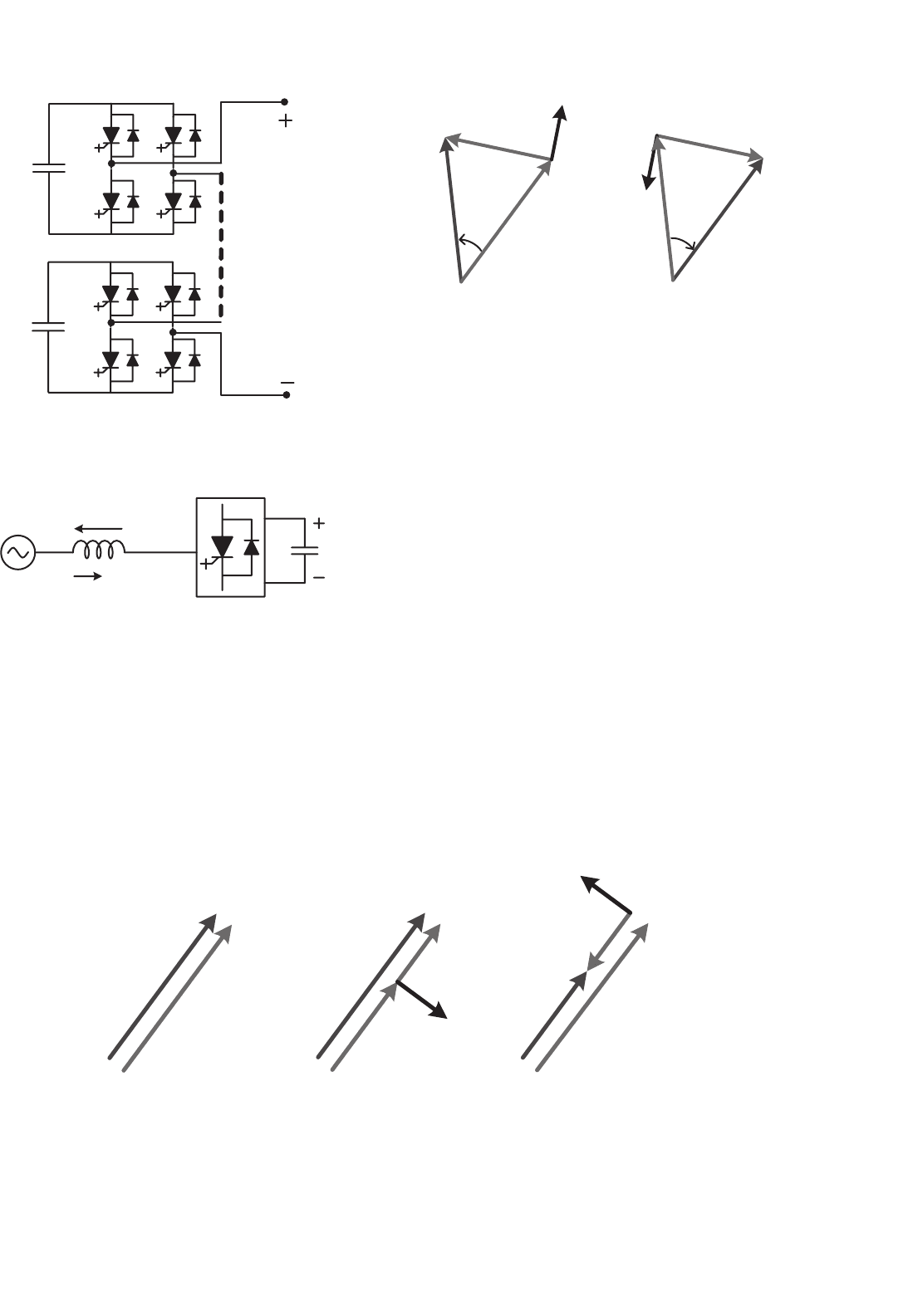
31.4.2.1.5 Cascade Converter The basic cascade converter
[21] topology is shown in Fig. 31.27. Only two single-phase full
bridge converters are shown, the first and the nth. However,
in actual application, several of them are connected in series
and switched at line frequency. The resulting voltage waveform
can be similar to the multi-pulse converter waveform with the
advantage that there is no need of transformers to sum up the
converters output voltage. Due to the line frequency switch-
ing, the switching losses are very low. The resulting voltage
waveform can be almost sinusoidal depending on the number
of series converters and the transformer used to connect them
to the grid can be a conventional sinusoidal waveform trans-
former, if necessary. One drawback of this converter topology
is that it is not possible to have a back-to-back connection. The
need to have one DC capacitor for each single-phase converter
has two consequences: the number of capacitors is equal to
the number of single-phase converters; and the capacitance of
each capacitor has to be much higher, if compared with three-
phase converters. This is because the instantaneous power in
the single-phase converter has a large oscillating component at
double of the line frequency and it would force a large voltage
ripple in the capacitor if they were small.
31.4.2.1.6 STATCOM Control Techniques The control of
reactive power in the STATCOM is done by controlling its
terminal voltage. Figure 31.28 shows a simplified circuit where
the AC grid is represented by a voltage source V
S
behind an
impedance X
L
and the STATCOM is represented by its fun-
damental voltage V
I
. Figure 31.29a shows the case when the
AC grid phasor voltage V
S
is in phase with the STATCOM
voltage V
I
and both have the same magnitude. In this case,
the line current I
L
is zero. Figure 31.28b shows the case when
V
S
is a little larger than V
I
. In this case, the line current I
L
,
810 E. H. Watanabe et al.
C
d
V
d
i
c
(t)
i
b
(t)
i
a
(t)
v
a
(t)
v
b
(t)
v
c
(t)
FIGURE 31.22 6-Pulse 2-level VSI-based 24-pulse var compensator.
31 Flexible AC Transmission Systems 811
t
v(t)
(a)
(b)
1
23 25
0.25
0.50
0.75
1.00
Harmonic order
Voltage phase-neutral (pu)
FIGURE 31.23 (a) 24-Pulse converter voltage waveform and (b) its
harmonic spectrum.
t
v(t)
(a)
(b)
1
47 49
0.25
0.50
0.75
1.00
Harmonic order
Voltage phase-neutral (pu)
FIGURE 31.24 (a) 48-Pulse converter voltage waveform and (b) its
harmonic spectrum.
which lags the voltage V
L
by 90
◦
, is also lagging the AC grid
phasor voltage V
S
, and therefore the STATCOM is producing
an inductive reactive power. On the other hand, Fig. 31.29(c)
shows the case when V
S
is a little smaller than V
I
. As a result,
the line current I
L
, which lags the voltage V
L
by 90
◦
, leads
the voltage V
S
, and therefore the STATCOM is producing a
capacitive reactive power. In summary, the STATCOM reac-
tive power can be controlled if the magnitude of its V
I
voltage
is controlled, assuming that it is in phase with V
S
.
–ifV
S
is equal to V
I
there is no reactive power and no
active power in the STATCOM;
–ifV
S
is larger than V
I
the STATCOM reactive power is
inductive;
–ifV
S
is smaller than V
I
the STATCOM reactive power is
capacitive.
The reactive power control in a STATCOM is, therefore, a
problem of how to control the magnitude of its voltage V
I
.
There are two basic principles: in the case of multi-pulse con-
verters, the output voltage magnitude can only be controlled
by controlling the DC side voltage that is the DC capacitor
voltage; in the case of PWM control, the DC capacitor voltage
can be kept constant and the voltage can be controlled by the
PWM controller itself.
Figure 31.30a shows the phasor diagram for the case when
a phase difference δ between V
S
and V
I
is positive. The result-
ing line current is in such a way that produces an active
power flowing into the converter, charging the DC capacitor.
Figure 31.30b shows the phasor diagram for a negative phase
angle δ. In this case the DC capacitor is discharged. Therefore,
by controlling the phase angle δ it is possible to control the
DC capacitor voltage.
In general, STATCOM based on multi-pulse converter with-
out PWM has to control its voltage by charging or discharging
the DC capacitor and this voltage has to be variable. On the
other hand, STATCOM based on a PWM-controlled con-
verter has to control DC side capacitor voltage only to keep
it constant. In both cases, the principle shown in Fig. 31.30 is
valid.
The STATCOM control technique presented above illus-
trates the basic scalar control concepts. However, this com-
pensator can be also controlled by a vector technique [22].
In this case, the three-phase voltages are transformed to a syn-
chronous reference frame where they can be controlled in such
a way as to regulate the quadrature component of the cur-
rent, which controls reactive power. The direct component of
the current are used to control the DC capacitor voltage as it
represents the active power.
Another way to control the STATCOM is by using the
instantaneous power theory [23, 24]. This theory was first pro-
posed for controlling active power filters and is used in the
design of the compensators operating with unbalanced sys-
tems. If a high frequency PWM converter is used, this theory
allows the design of active filters to compensate for harmonic
components or fundamental reactive component.
31.4.2.1.7 STATCOM DC Side Capacitor Theoretically the
DC side capacitor of a STATCOM based on three-phase con-
verters operating in a balanced system and controlling only
reactive power could have a capacitance equal to zero Farad.
However, in actual STATCOMs, a finite capacitor has to be
used with the objective of keeping constant or controlled DC
voltage as it tends to vary due to the converter switching.
One parameter commonly used in synchronous machine is

812 E. H. Watanabe et al.
α
5
α
4
α
3
α
1
α
2
0
π
2
0 0.2 0.4 0.6 0.8 1
0.2
0.4
0.6
0.8
1.0
1.2
Modulation index,m
a
(pu)
PWM control angle, α (rad)
α
5
α
4
α
3
α
2
α
1
(a) (b)
FIGURE 31.25 (a) Example of one-phase voltage with the harmonic elimination technique and (b) the control angle as function of the modulation
index.
1 1719 2325
0.25
2.00
1.75
1.50
1.25
1.00
0.75
0.50
Phase-to-phase Voltage, (pu)
1 1719 2325
Harmonic order
FIGURE 31.26 Line voltage harmonic spectrum for the voltage waveform in Fig. 31.25a.
the inertia constant H defined by
H =
Jω
2
/2
S
(31.10)
where J and ω are the rotor moment of inertia and angu-
lar speed and S is the machine apparent power. A similar
parameter for the STATCOM, H
ST
, can be defined by
H
ST
=
CV
2
DC
/2
S
(31.11)
where C and V
DC
are the DC capacitance and its voltage and
S is the STATCOM apparent power.
In both cases, the constants H and H
ST
are values in time
units corresponding to the relation of the amount of energy
stored in the rotor inertia or in the capacitor and the machine
or STATCOM apparent power. In the case of synchronous
machines, the value of H is in the range of few seconds (gen-
erally, in the range of 1–3 s) and in the case of the STATCOM,
H
ST
is in the range of milliseconds or below (0.5–5 ms) if only
reactive power is to be controlled. These numbers show that
the STATCOM based on three-phase converters and designed
for reactive power control only (which is the general case),
has almost no stored energy in its DC capacitor. On the other
hand, STATCOM based on single-phase converters without a
common DC link may have larger capacitors, as in the case of
31 Flexible AC Transmission Systems 813
V
k
(k = a,b,c)
V
d
n
C
d
n
V
d
1
C
d
1
FIGURE 31.27 Cascade converter basic topology.
j XL
V
L
I
L
AC Grid
STATCOM
V
S
V
I
C
d
V
d
FIGURE 31.28 Simplified circuit for the AC grid and the STATCOM.
cascade converters due to the power oscillations at double of
the line frequency.
There are STATCOMs (in some cases with different names)
that are designed for operation with unbalanced loads. In this
case, the DC capacitor has to be also much larger than in
the case of balanced systems to avoid large voltage ripple
V
S
V
I
I
L
V
I
V
L
V
S
I
L
V
I
V
L
V
S
V
S
= V
I
V
S
> V
I
V
S
< V
I
(a) (b) (c)
FIGURE 31.29 Reactive power control in a STATCOM.
V
I
δ > 0
V
S
V
S
V
I
V
L
V
L
δ < 0
I
L
I
L
(
a
)(
b
)
δ
δ
FIGURE 31.30 Active power control in a STATCOM.
on the DC voltage due to power oscillations at twice the
line frequency, which appears naturally in unbalanced systems
[25, 26] or unbalanced voltages [27] or system with flicker
problem [28, 29]. In this case, the STATCOM compensates
reactive power as well as the instantaneous oscillating active
power due to the negative sequence currents components. In
fact, this is an extension of the shunt active power filter appli-
cation where the goal is the current harmonic compensation,
which includes negative sequence currents even at the funda-
mental frequency. If sub-harmonics are present, the device is
able to filter them out as well.
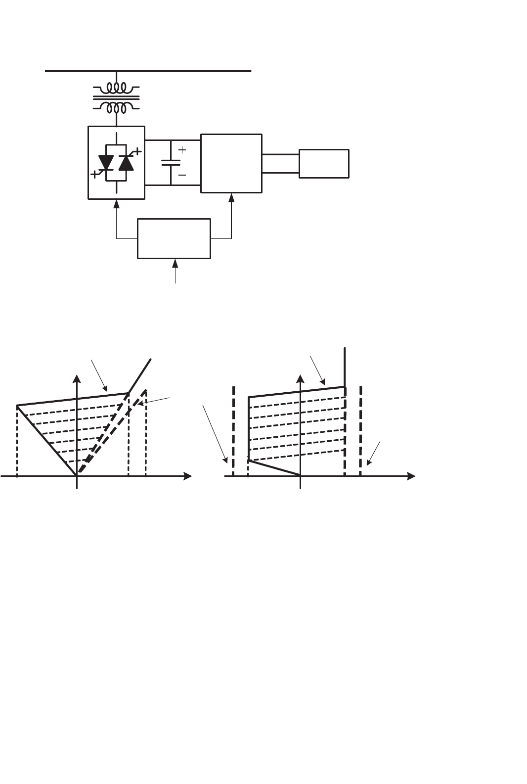
31.4.2.1.8 STATCOM with Energy Storage In general, the
STATCOM is designed for reactive power compensation and
it does not need large energy storage elements. However,
there are some applications where it may be interesting to
have some energy stored in the DC side, for example to
compensate for active power for a short time. In these appli-
cations, the DC side capacitor has to be substituted by a
voltage source energy storage device like a battery [30] or
814 E. H. Watanabe et al.
DC-DC
Converter
SMES
Superconducting
Magnetic Energy Storage
Controller
Voltage
Source
Inverter
P and Q
References
AC Bus
Coupling
Transformer
C
d
V
d
FIGURE 31.31 STATCOM with SMES.
Capacitive
(b)
InductiveCapacitiveInductive
v
Bus
v
Bus
(a)
i
i
Transient
operation
Continuous
operation
Continuous
operation
Transient
operation
FIGURE 31.32 Comparison between SVC and STATCOM.
a double layer capacitor (super capacitor). Another possi-
bility is to store energy in superconducting magnetic energy
storage (SMES) systems [31, 32]. A natural solution for the
use of the superconducting reactor would be the connec-
tion to the AC grid through a current source inverter (CSI)
instead of the voltage source inverter. However, this has not
been the case found in the literature. Figure 31.31 shows a
block diagram of a typical STATCOM/SMES system, where
the SMES is connected to the DC side of the STATCOM
through a DC–DC converter which converts the direct current
in the superconductor magnet to DC voltage in the STAT-
COM DC side and vice versa. This STATCOM is able to
control reactive power continuously, as well as active power
for a short time, depending on the amount of energy stored in
the superconducting magnet.
31.4.2.1.9 Comparison between SVC and STATCOM
Figure 31.32a shows the steady-state volt–ampere character-
istics for the SVC shown in Fig. 31.14, while Fig. 31.32b shows
the same characteristics for a STATCOM. For operation at
rated voltage, both devices can present similar characteristics
in terms of control range. However, SVC current compensa-
tion capability for lower voltages becomes smaller, while in
the STATCOM it does not change significantly for voltages
lower than rated (but approximately above 0.2 pu). This is
explained by the fact that the SVC is based on impedance