Power electronic handbook
Подождите немного. Документ загружается.

428 S. Y. Hui and H. S. H. Chung
ω
0
t
i
Lr
v
Cr
T
1
D
1
I
o
0
t
3
t
2
t
1
t
0
t
5
t
4
(a)
ω
0
t0
v
Cr
i
Lr
T
1
D
1
T
2
D
2
D
2
(b)
ω
0
t0
v
Cr
i
Lr
T
1
D
1
T
2
D
2
D
1
(c)
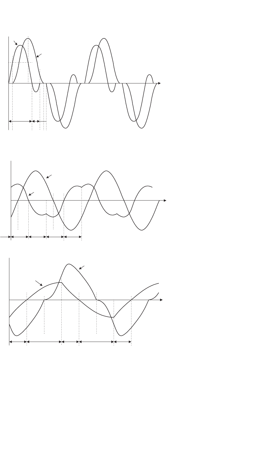
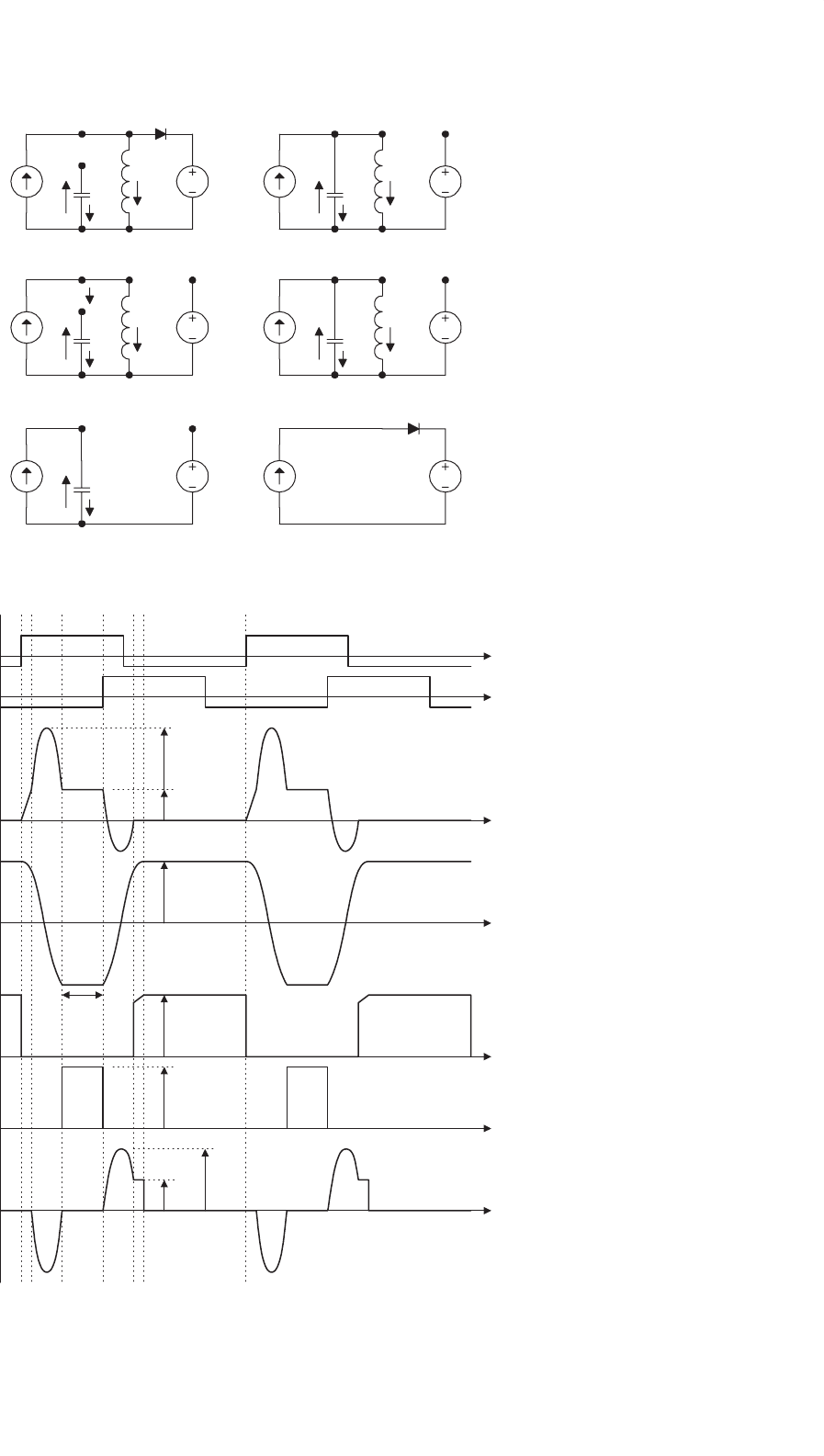
FIGURE 16.27 Circuit waveforms under different operating conditions: (a) discontinuous conduction mode; (b) continuous conduction mode
ω
S
<ω
r
; and (c) continuous conduction mode ω
S
>ω
r
.
16 Resonant and Soft-switching Converters 429
0
1
2
3
4
5
012
γ
M
0.8
1
r=3
2
1.27
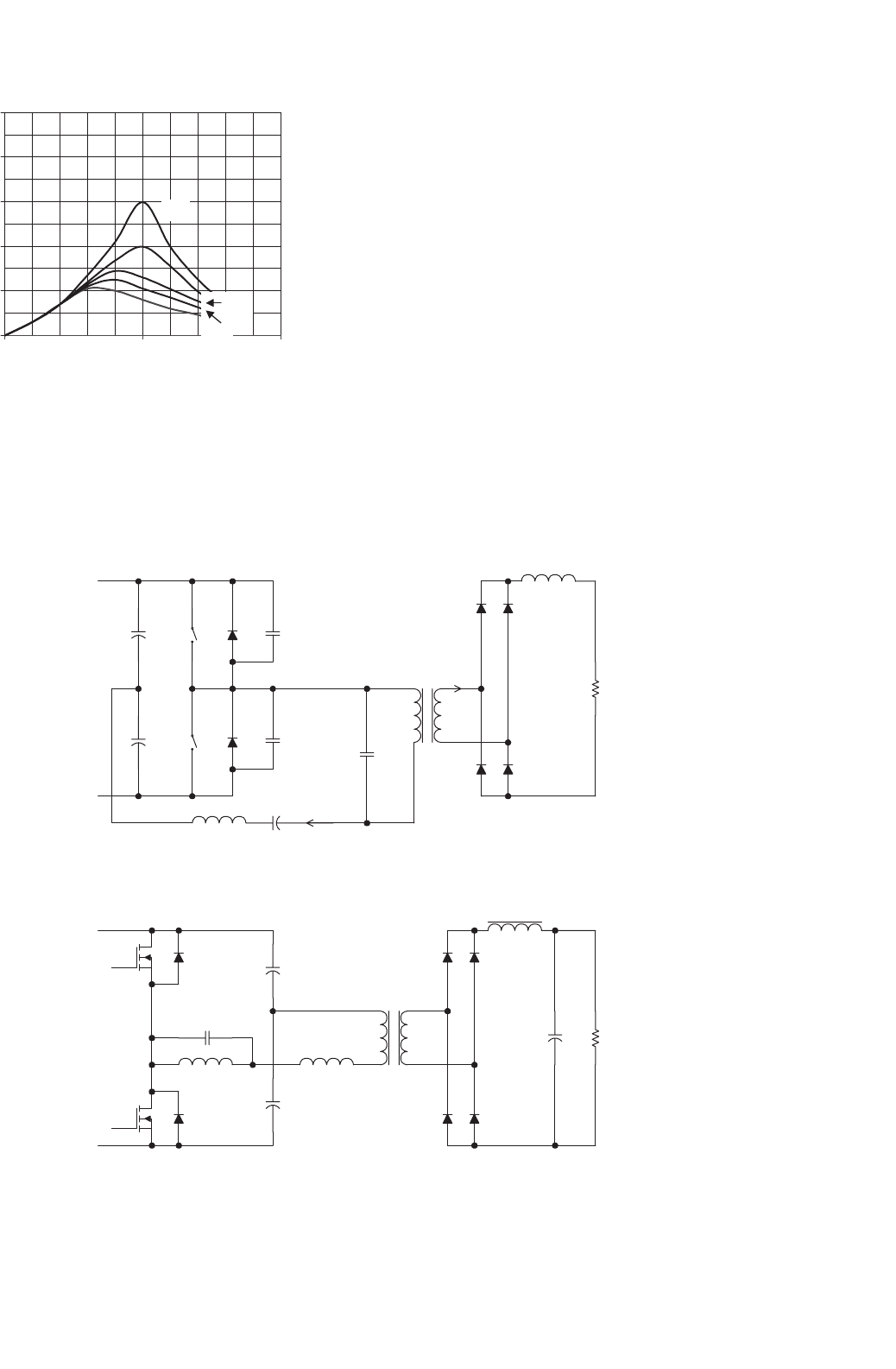
FIGURE 16.28 M vs γ in PRC.
C
1
C
2
T
1
C
L
R
L
D
1
D
6
D
8
D
7
D
5
D
2
+
V
s
−
+
V
o
−
C
p
L
o
n:1
L
s
Q
1
Q
2
L
p
S
1
S
2
R
L
D
1
D
2
i
+
V
s
−
+
E
−
+
E
−
+
V
o
−
AB
L
d
T
1
D
2
D
4
D
3
D
1
C
s
n:1
L
s
C
n
C
n
C
t
i
rect.in
dc link
inductor
(a)
(b)
FIGURE 16.29 Different types of SPRC: (a) LCC-type and (b) LLC-type.
values and can come from the snubber circuits of a standard
hard-switched converter. Thus, the only additional compo-
nent is the auxiliary switch Q2. The small resonant inductor
is put in series with the main switch SW1 so that SW1 can be
switched on under ZC condition and the di/dt problem of the
reverse-recovery current be eliminated. The resonant capaci-
tor C
r
is used to store energy for creating condition for soft
switching. Q2 is used to control the resonance during the main
switch transition. It should be noted that all power devices
including SW1, Q1 and main power diode D
F
are turned on
and off under ZV and/or ZC conditions. Therefore, the large
di/dt problem due to the reverse recovery of the power diode
can be eliminated. The soft-switching method is an effective
technique for EMI suppression.
Together with power factor correction technique, soft-
switching converters offer a complete solution to meet EMI
regulations for both conducted and radiated EMI. The opera-
tion of the EP-QR boost PFC circuit [34, 35] can be described
in six modes as shown in Fig. 16.35. The corresponding
idealized waveforms are included in Fig. 16.36.
430 S. Y. Hui and H. S. H. Chung
One
Shot
Fault
Logic
and
Precision
Reference
VCO
0.5V
RC
Zero
Cvco
Rmin
Range
E/A Out
INV
NI
Soft-Ref
Fault
3V
+
−
Steering
Logic
FET
Drivers
UVLO
Bias &
5V Gen
5V
Gnd
Vcc
Out A
Out B
Pwr Gnd
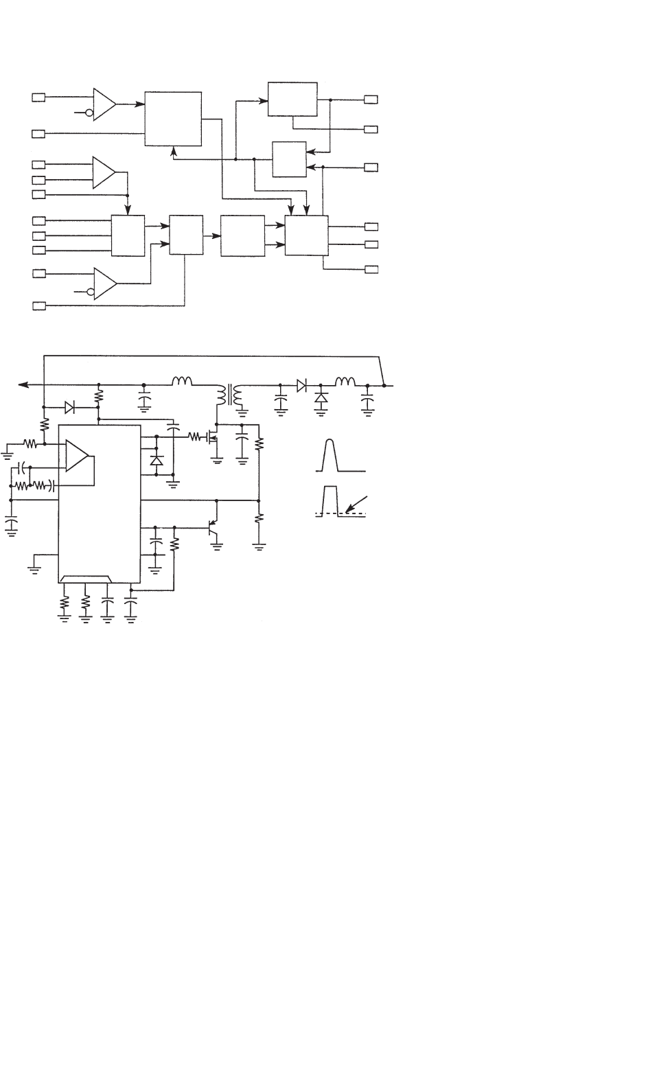
FIGURE 16.30 Controller block diagram of UC1864 (Courtesy of Unitrode Corp. and Texas Instruments).
Vin
50V
7k
5k
Soft
Ref
1864
Zero
5V
Gnd
RC
Fault
VCO
PGND
A
B
VCC
22k
Vs
100k
Vout
12V
Vz
Vs
5.1k
0.5
0
0
Vz
+
−
FIGURE 16.31 ZV-MR forward converter (Courtesy of Unitrode Corp. and Texas Instruments).
A. Circuit Operation
Interval I: (t
0
−t
1
) Due to the resonant inductor L
r
which
limits the di/dt of the switch current, switch SW1 is turned on
at zero-current condition with a positive gating signal V
GS1
to
start a switching cycle at t = t
0
. Current in D
F
is diverted to
inductor L
r
. Because D
F
is still conducting during this short
period, D
S2
is still reverse biased and is thus not conducting.
The equivalent circuit topology for the conducting paths is
shown in Fig. 16.35a. Resonant switch Q
2
remains off in this
interval.
Interval II: (t
1
−t
a
) When D
F
regains its blocking state,
D
S2
becomes forward biased. The first half of the resonance
cycle occurs and resonant capacitor C
r
starts to discharge
and current flows in the loop C
r
−Q
2
−L
r
−SW
1
. The reso-
nance half-cycle stops at time t = t
a
because D
S2
prevents the
loop current i
Cr
from flowing in the opposition direction. The
voltage across C
r
is reversed at the end of this interval. The
equivalent circuit is shown in Fig. 16.35b.
Interval III: (t
a
−t
b
) Between t
a
and t
b
, current in L
F
and
L
r
continues to build up. This interval is the extended-period
for the resonance during which energy is pumped into L
r
. The
corresponding equivalent circuit is showed in Fig. 16.35c.
Interval IV: (t
b
−t
2
) Figure 16.35d shows the equivalent cir-
cuit for this operating mode. Before SW
1
is turned off, the
second half of the resonant cycle needs to take place in order
that a zero-voltage condition can be created for the turn-off
process of SW
1
. The second half of the resonant cycle starts
when auxiliary switch Q
2
is turned on at t = t
b
. Resonant cur-
rent then flows through the loop L
r
−Q
2
−C
r
-anti-parallel diode
16 Resonant and Soft-switching Converters 431
RT
CT
SYNC
RAMP
EAOUT
EAP
EAN
CS
SS
12
19
2.5V
REF
HI=ON
HI=ON
0.5V
S
R
DISABLE
COMPARATOR
Q
Q
Q
Q
Q
Q
20
2
3
0.8V
6
7
8
OSC
PWM
COMPARATOR
ERROR
AMP
NO LOAD
COMPARATOR
CURRENT SENSE
COMPARATOR
0.5VI
06.V
D
D
S
DELAY C
DELAY B
DELAY A
DELAY D
ADAPTIVE DELAY
SET AMPLIFIER
UVLO COMPARATOR
0.5V
REF
REF
GND
ADS
11
16
13
10
14
17
18
15
9
PGND
OUTD
DELCD
OUTC
OUTB
DELAB
OUTA
VDD
REFERENCE OK
COMPARATOR
4V
11V/9V
4
5
S
R
R
Q
Q
D
S
R
OVER CURRENT
COMPARATOR
+
+
+
−
+
−
+
+
−
+
−
−
−
+
−
+
+
−
−
Q
Q
I
RT
8(I
RT
)
I
RT
10(I
RT
)
2V
1
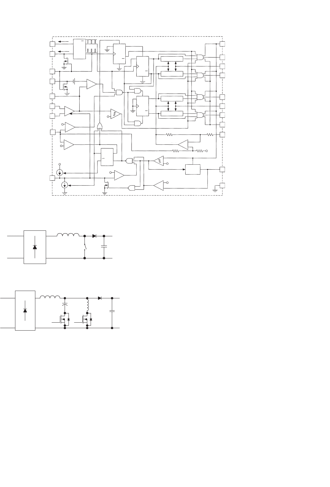
FIGURE 16.32 Application diagram of UCC3895 (Courtesy of Unitrode Corp. and Texas Instruments).
L
F
D
F
SW C
F
1-phase
AC supply
FIGURE 16.33 Boost-type AC–DC power factor correction circuit.
L
F
D
F
C
F
1-phase
AC supply
Q2
L
r
C
r
Ds2
SW1
FIGURE 16.34 EP-QR boost-type AC–DC power factor correction
circuit.
of SW
1
. This current is limited by L
r
and thus Q
2
is turned on
under zero-current condition. Since the anti-parallel diode of
SW
1
is conducting, the voltage across SW
1
is clamped to the
on-state voltage of the anti-parallel diode. SW
1
can therefore
be turned off at (near) zero-voltage condition before t = t
2
at
which the second half of the resonant cycle ends.
Interval V: (t
2
−t
3
) During this interval, the voltage across C
r
is less than the output voltage V
o
. Therefore D
F
is still reverse
biased. Inductor current I
s
flows into C
r
until V
Cr
reaches V
o
at t = t
3
. The equivalent circuit is represented in Fig. 16.35e.
Interval VI: (t
3
−t
4
) During this period, the resonant circuit
is not in action and the inductor current I
s
charges the output
capacitor C
F
via D
F
, as in the case of a classical boost-type
PFC circuit. C
r
is charged to V
o
, therefore Q
2
can be turned
off at zero-voltage and zero-current conditions. Figure 16.35f
shows the equivalent topology of this operating mode.
In summary, SW1, Q2, and D
F
are fully soft-switched. Since
the two resonance half-cycles take place within a closed loop
outside the main inductor, the high resonant pulse will not
occur in the inductor current, thus making a well-established
averaged current mode control technique applicable for such
QR circuit. For full soft-switching in the turn-off process, the
resonant components need to be designed so that the peak
resonant current exceeds the maximum value of the inductor
current. Typical measured switching waveforms and trajec-
tories of SW1, Q2 and D
F
are shown in Figs. 16.37, 16.38,
and 16.39, respectively.
B. Design Procedure
Given: Input AC voltage = V
s
(V)
Peak AC voltage = V
s
(max) (V)
Nominal output DC voltage = V
o
(V)
Switching frequency = f
sw
(Hz)
Output power = P
o
(W)
432 S. Y. Hui and H. S. H. Chung
L
r
C
r
I
S
V
o
i
Lr
i
Cr
V
Cr
(b)
L
r
D
F
C
r
I
S
V
o
i
Lr
i
Cr
V
Cr
(a)
L
r
C
r
I
S
V
o
i
Lr
i
Cr
V
Cr
(c)
V
G2
L
r
C
r
I
S
V
o
i
Lr
i
Cr
V
Cr
(d)
D
F
I
S
V
o
(f)
C
r
I
S
i
Cr
V
Cr
(e)
FIGURE 16.35 Operating modes of EP-QR boost-type AC–DC power factor correction circuit.
V
GS1
i
Cr
V
Q2
V
SW1
V
Cr
i
Lr
V
GS2
V
o
/Z
n
I
S
V
o
V
o
V
o
V
o
/Z
n
I
S
t
e
t
0
t
a
t
4
t
3
t
2
t
b
t
1
t
VIVIVIIIIII
FIGURE 16.36 Idealized waveforms of EP-QR boost-type AC–DC power factor correction circuit.
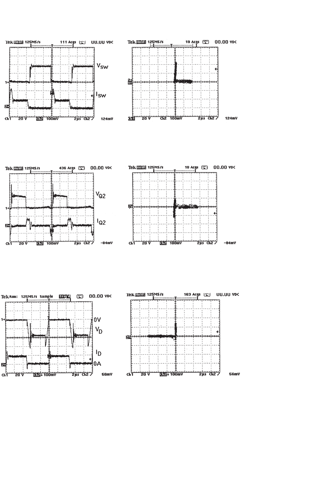
16 Resonant and Soft-switching Converters 433
(a) (b)
FIGURE 16.37 (a) Drain-source voltage and current of SW1 and (b) switching locus of SW1.
(a) (b)
FIGURE 16.38 (a) Drain-source voltage and current of Q2 and (b) switching locus of Q2.
(a) (b)
FIGURE 16.39 (a) Diode voltage and current and (b) switching locus of diode.

434 S. Y. Hui and H. S. H. Chung
Input current ripple = I (A)
Output voltage ripple = V (V)
(I) Resonant tank design:
Step 1: Because the peak resonant current must be greater
than the peak inductor current (same as peak input line
current) in order to achieve soft-turn-off, it is necessary to
determine the peak input current I
s
(max). Assuming lossless
AC–DC power conversion, I
s
(max) can be estimated from the
following equation
I
s(max)
≈
2V
o
I
o
V
s(max)
(16.7)
where I
o
= P
o
/V
o
is the maximum output current.
Step 2: Soft-switching criterion is
Z
r
≤
V
o
I
s(max)
(16.8)
where Z
r
=
L
r
C
r
is the impedance of the resonant tank.
For a chosen resonant frequency f
r
, L
r
, and C
r
can be
obtained from:
2πf
r
=
1
√
L
r
C
r
(16.9)
(II) Filter component design:
The minimum conversion ratio is
M
(min)
=
V
o
V
s(max)
=
1
1 −
f
sw
f
r
+
t
e
T
sw
(16.10)
where T
sw
= 1/f
sw
and t
e
is the extended period. From
Eq. (16.10), minimum t
e
can be estimated.
The turn-on period of the SW1 is
T
on
(sw1) = t
e
+1/f
r
(16.11)
Inductor value L is obtained from:
L ≥
T
on(sw1)
I
V
s(max)
(16.12)
The filter capacitor value C can be determined from:
C
V
T
s
π
sin
−1
I
o
I
s(max)
= I
o
(16.13)
where T
s
= 1/f
s
is the period of the AC voltage supply
frequency.
16.11.1 Soft-switched DC–DC Flyback
Converter
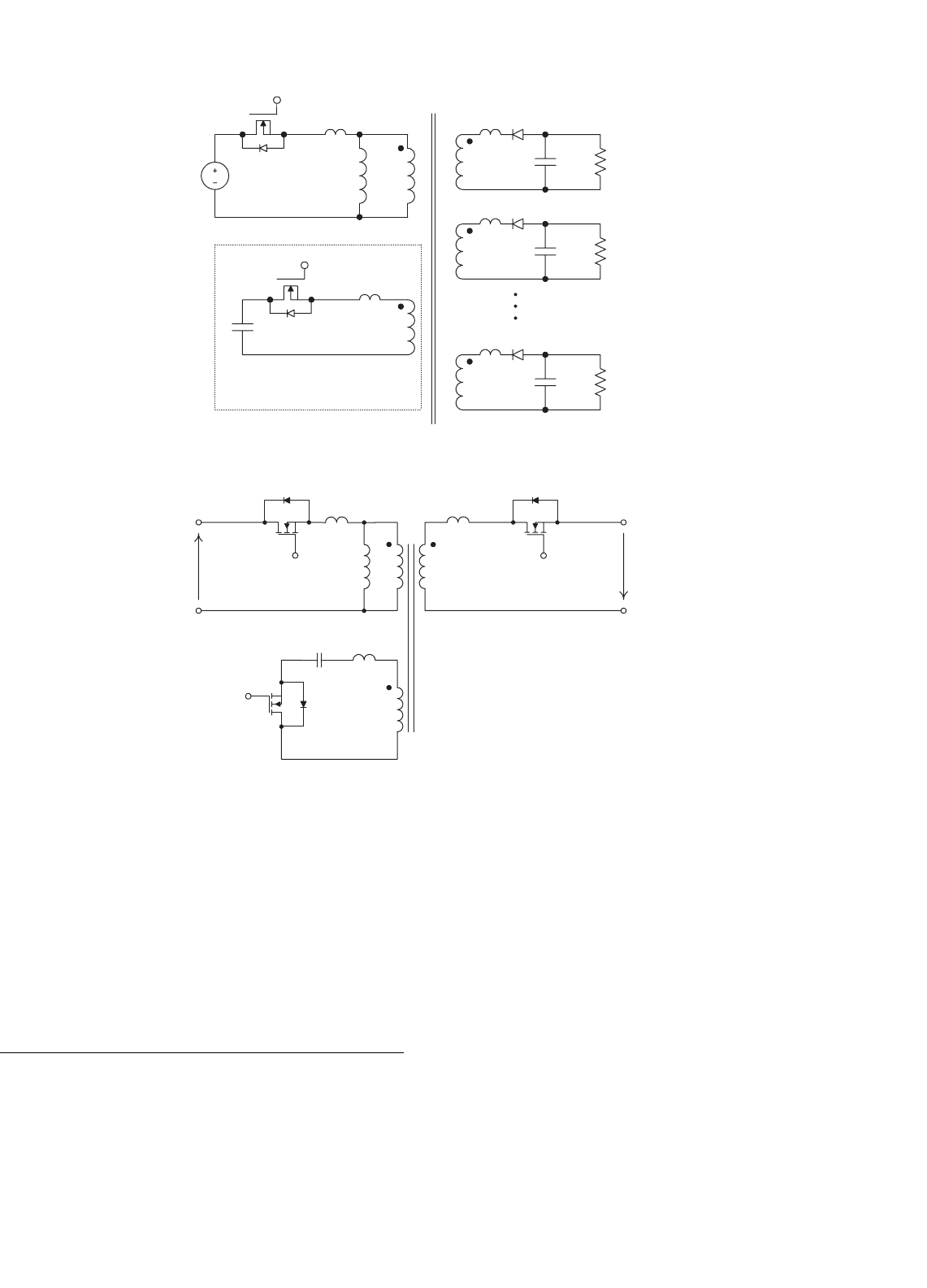
A simple approach that can turn an existing hard-switched
converter design into a soft-switched one is shown in
Fig. 16.40. The key advantage of the proposal is that many
well proven and reliable hard-switched converter designs can
be kept. The modification required is the addition of a simple
circuit (consisting an auxiliary winding, a switch, and a small
capacitor) to an existing isolated converter [36]. This princi-
ple, which is the modified version of the EPQR technique for
isolated converter, is demonstrated in an isolated soft-switched
flyback converter with multiple outputs. Other advantageous
features of the proposal are:
• All switches and diodes of the converter are ‘fully’
soft-switched, i.e. soft-switched at both turn-on and turn-
off transitions under zero-voltage and/or zero-current
conditions.
• The leakage inductance of each winding in the fly-
back transformer forms part of the resonant circuit for
achieving ZVS and ZCS of all switches and diodes.
• The control technique is simply PWM-based as in
standard hard-switched converters.
• The soft-switched technique is a proven method for EMI
reduction [37].
16.11.2 A ZCS Bidirectional Flyback DC–DC
Converter
A bi-directional flyback dc–dc converter that uses one auxiliary
circuit for both power flow directions is proposed in Fig. 16.41
[38]. The methodology is based on extending the unidirec-
tional soft-switched flyback converter in [36] and replacing
the output diode with a controlled switch, which acts as either
a rectifier [39] or a power control switch in the correspond-
ing power flow direction. An auxiliary circuit that consists of
a winding in the coupled inductor, a switch, and a capacitor
converts the hard-switched design into a soft-switched one.
The operation is the same as [36] in the forward mode. An
extended-period resonant stage [34] is introduced when the
power control switch is on. Conversely, in the reverse mode,
a complete resonant stage is initiated before the main switch
is off. In both the power flow operations, the leakage induc-
tance of the coupled inductor is used to create zero-current
switching conditions for all switches.
16.12 Soft-switching and EMI
Suppression
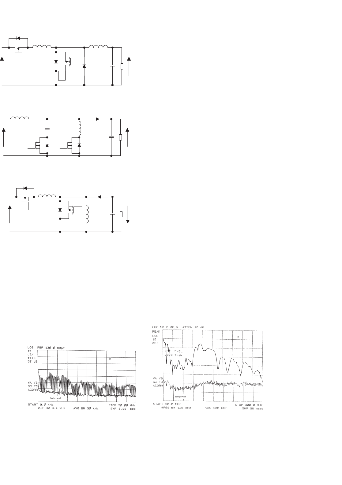
A family of EP-QR converters are displayed in Fig. 16.42. Their
radiated EMI emission have been compared with that from
their hard-switched counterparts [37]. Figures 16.43a, b show
the conducted EMI emission from a hard-switched flyback
16 Resonant and Soft-switching Converters 435
auxiliary circuit
L
O1
D
O1
n
O1
C
O1
R
L1
−
v
O1
+
n
a
L
a
S
a
D
a
C
a
L
O2
D
O2
n
O2
C
O2
R
L2
−
v
O2
+
L
ON
D
ON
n
ON
C
ON
R
LN
−
v
ON
+
S
p
L
p
D
p
L
m
n
p
V
i
FIGURE 16.40 Fully soft-switched isolated flyback converter.
S
1
D
1
S
2
D
2
v
1
v
2
n
1
n
2
L
k2
n
3
L
k3
S
3
D
3
C
a
L
k1
L
m
FIGURE 16.41 Bidirectional soft-switched isolated flyback converter.
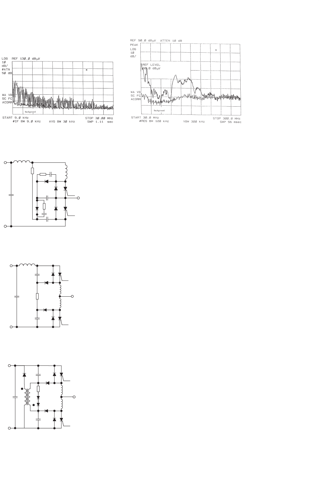
converter and a soft-switched one, respectively. Their radiated
EMI emissions are included in Fig. 16.44. Both converters are
tested at an output power of 50 W. No special filtering or
shielding measures have been taken during the measurement.
It is clear from the measurements that soft-switching is an
effective means to EMI suppression.
16.13 Snubbers and Soft-switching for
High Power Devices
Today, most of the medium power (up to 200 kVA) and
medium voltage (up to 800 V) inverter are hard-switched.
Compared with low-power switched mode power supplies, the
high voltage involved in the power inverters makes the dv/dt,
di/dt, and the switching stress problems more serious. In addi-
tion, the reverse recovery of power diodes in the inverter leg
may cause very sharp current spike, leading to severe EMI
problem. It should be noted that some high power devices
such as GTO thyristors do not have a square safe operating
area (SOA). It is therefore essential that the switching stress
they undergone must be within their limits. Commonly used
protective measures are to use snubber circuits for protecting
high power devices.
Among various snubbers, two snubber circuits are most
well-known for applications in power inverters. They are the
Undeland snubber [40] (Fig. 16.45) and McMurray snub-
ber circuits [41] (Fig. 16.46). The Undeland snubber is an
asymmetric snubber circuit with one turn-on inductor and
one turn-off capacitor. The turn-off snubber capacitor C
s
is
clamped by another capacitor C
c
. At the end of each switching
436 S. Y. Hui and H. S. H. Chung
SW
Q
D
L
r
L
C
r
C
R
L
V
out
V
in
(a)
C
R
L
V
out
V
in
D
C
r
Q
L
SW
L
r
(b)
SW
Q
L
r
C
r
C
R
L
V
out
V
in
D
L
(c)
FIGURE 16.42 A family of EP-QR converters: (a) buck converter;
(b) boost converter; and (c) flyback converter.
cycle, the snubber energy is dumped into C
c
and then dis-
charged into the dc bus via a discharge resistor. In order to
reduce the snubber loss, the discharge resistor can be replaced
by a switched mode circuit. In this way, the Undeland snubber
can become a snubber with energy recovery. The McMurray
(a) (b)
FIGURE 16.43 (a) Conducted EMI from hard-switched flyback converter and (b) radiated EMI from hard-switched flyback converter.
snubber is symmetrical. Both the turn-off snubber capacitors
share current in parallel during turn off. The voltage transient
is limited by the capacitor closest to the turning-off device
because the stray inductance to the other capacitor will pre-
vent instantaneous current sharing. The turn-on inductors
require mid-point connection. Snubber energy is dissipated
into the snubber resistor. Like the Undeland snubber, the
McMurray snubber can be modified into an energy recovery
snubber. By using an energy recovery transformer as shown in
Fig. 16.47, this snubber becomes a regenerative one. Although
other regenerative circuits have been proposed, their complex-
ity makes them unattractive in industrial applications. Also,
they do not necessarily solve the power diode reverse-recovery
problems.
Although the use of snubber circuits can reduce the switch-
ing stress in the power devices, the switching loss is actually
damped into the snubber resistors unless regenerative snub-
bers are used. The switching loss is still a limiting factor to the
high frequency operation of power inverters. However, the
advent of soft-switching techniques opens a new way to high-
frequency inverter operation. Because the switching trajectory
of a soft-switched switch is close to the voltage and current
axis, faster power electronic devices with smaller SOAs can in
principle be used. In general, both ZVS and ZCS can reduce
switching loss in high-power power switches. However, for
power switches with tail currents, such as IGBT, ZCS is more
effective than ZVS.
16.14 Soft-switching DC–AC Power
Inverters
Soft-switching technique not only offers a reduction in switch-
ing loss and thermal requirement, but also allows the possibil-
ity of high frequency and snubberless operation. Improved
circuit performance and efficiency, and reduction of EMI
emission can be achieved. For zero-voltage switching (ZVS)
inverter applications, two major approaches which enable
16 Resonant and Soft-switching Converters 437
(a) (b)
FIGURE 16.44 (a) Conducted EMI from soft-switched flyback converter and (b) radiated EMI from soft-switched flyback converter.
L
s
C
s
C
c
C
dc
Undeland
FIGURE 16.45 Undeland snubber.
McMurray
L
s/2
C
s/2
C
dc
L
s/2
C
s/2
FIGURE 16.46 McMurray snubber.
L
s/2
C
s/2
C
dc
L
s/2
C
s/2
N
1
N
2
FIGURE 16.47 McMurray snubber with energy recovery.
inverters to be soft-switched have been proposed. The first
approach pulls the dc link voltage to zero momentarily so
that the inverter’s switches can be turned on and off with
ZVS. Resonant dc link and quasi-resonant inverters belong
to this category. The second approach uses the resonant pole
idea. By incorporating the filter components into the inverter
operation, resonance condition and thus zero voltage/current
conditions can be created for the inverter switches.
In this section, the following soft-switched inverters are
described.
Approach 1: Resonant dc link inverters
1. Resonant (pulsating) dc link inverters
2. Actively-clamped resonant dc link inverters
3. Resonant inverters with minimum voltage stress
4. Quasi-resonant soft-switched inverter
5. Parallel resonant dc link inverter.
Approach 2: Resonant pole inverters
1. Resonant pole inverters
2. Auxiliary resonant pole inverters
3. Auxiliary resonant commutated pole inverters.
Type 1 is the resonant dc link inverter [42–44] which sets
the dc link voltage into oscillation so that the zero-voltage
instants are created periodically for ZVS. Despite the poten-
tial advantages that this soft-switching approach can offer,
a recent review on existing resonant link topologies for invert-
ers [45] concludes that the resonant dc link system results in
an increase in circuit complexity and the frequency spectrum
is restricted by the need of using integral pulse density modu-
lation (IPDM) when compared with a standard hard-switched
inverter. In addition, the peak pulsating link voltage of reso-
nant link inverters is twice the dc link voltage in a standard
hard-switched inverter. Although clamp circuits (Type 2) can
be used to limit the peak voltage to 1.3–1.5 per unit [44],
power devices with higher than normal voltage ratings have to
be used.