Power electronic handbook
Подождите немного. Документ загружается.

418 S. Y. Hui and H. S. H. Chung
I
PRI
0
I
D14
V
A
I
D15
V
B
0
0
0
0
0
V
PRI
t
0
t
1
t
3
t
4
t
2
FIGURE 16.13 Circuit waveforms of the phase-shifted, ZVT FB converter.
for both of them simultaneously. Multi-resonant switch con-
cept, which is an extension of the concept of the resonant
switch, has been developed to overcome such limitation. The
zero-current multi-resonant (ZC-MR) and zero-voltage multi-
resonant (ZV-MR) switches [12, 17] are shown in Fig. 16.14.
(b)
(a)
S
L
S
L
D
C D
S
L
r
C
D
DC
S
FIGURE 16.14 Multi-resonant switches: (a) ZC-MR switch and
(b) ZV-MR switch.
The multi-resonant circuits incorporate all major parasitic
components, including switch output capacitance, diode junc-
tion capacitance, and transformer leakage inductance into the
resonant circuit. In general, ZVS (half-wave mode) is more
favorable than ZCS in DC–DC converters for high-frequency
operation because the parasitic capacitance of the active switch
and the diode will form a part of the resonant circuit.
An example of a buck ZVS-MRC is shown in Fig. 16.15.
Depending on the ratio of the resonant capacitance C
D
/C
S
,
two possible topological modes, namely mode I and mode II,
can be operated [19]. The ratio affects the time at which the
voltages across the switch S and the output diode D
f
become
zero. Their waveforms are shown in Figs. 16.16a and b, respec-
tively. If diode voltage V
D
falls to zero earlier than the switch
V
i
C
S
C
D
C
f
L
r
L
f
R
L
D
f
D
S
S
+ V
S
−
+
V
Df
−
I
Df
I
o
V
o
I
Lr
FIGURE 16.15 Buck ZVS-MRC.
16 Resonant and Soft-switching Converters 419
ON
2
3
4
5
I
Lr
/I
o
−3
0
3
S
OFF
I
S
/I
o
−3
0
3
1
0
V
S
/V
i
2
3
1
0
I
Df
/I
o
2
3
1
0
V
f
/V
i
t
1
t
0
t
2
t
3
t
4
(a)
ON
2
3
4
5
S
OFF
1
0
V
S
/V
i
5
0
I
Df
/I
o
2
3
1
0
V
f
/V
i
t
1
t
0
t
2
t
3
t
4
I
Lr
/I
o
−
5
0
5
I
S
/I
o
−
5
0
5
(b)
FIGURE 16.16 Possible modes of the buck ZVS-MRC: (a) mode I and (b) mode II.

420 S. Y. Hui and H. S. H. Chung
voltage V
S
, the converter will follow mode I. Otherwise, the
converter will follow mode II.
Instead of having one resonant stage, there are three in this
converter. The mode I operation in Fig. 16.16a is described
first. Before the switch S is turned on, the output diode D
f
is
conducting and the resonant inductor current I
Lr
is negative
(flowing through the anti-parallel diode of S). S is then turned
on with ZVS. The resonant inductor current I
Lr
increases lin-
early and D
f
is still conducting. When I
Lr
reaches the output
current I
o
, the first resonant stage starts. The resonant circuit
is formed by the resonant inductor L
r
and the capacitor C
D
across the output diode. This stage ends when S is turned
off with ZVS. Then, a second resonant stage starts. The res-
onant circuit consists of L
r
, C
D
, and the capacitor across the
switch C
s
. This stage ends when the output diode becomes
forward biased. A third resonant stage will then start. L
r
and C
s
form the resonant circuit. This stage ends and completes one
operation cycle when the diode C
s
becomes forward biased.
The only difference between mode I and mode II in
Fig. 16.16b is in the third resonant stage, in which the reso-
nant circuit is formed by L
r
and C
D
. This stage ends when D
f
becomes forward biased. The concept of the multi-resonant
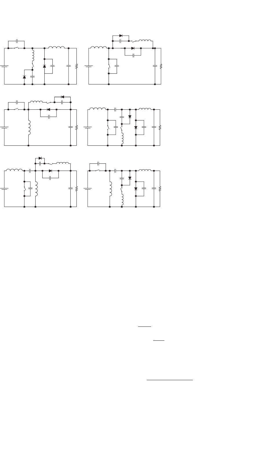
switch can be applied to conventional converters [19–21].
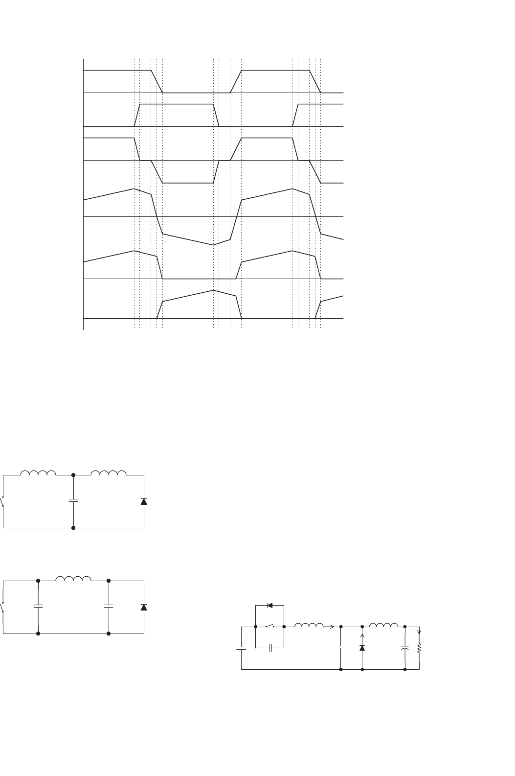
A family of MRCs are shown in Fig. 16.17.
Although the variation of the switching frequency for reg-
ulation in MRCs is smaller than that of QRCs, a wide-band
frequency modulation is still required. Hence, the optimal
design of magnetic components and the EMI filters in MRCs
is not easy. It would be desirable to have a constant switch-
ing frequency operation. In order to operate the MRCs with
constant switching frequency, the diode in Fig. 16.14 can be
replaced with an active switch S
2
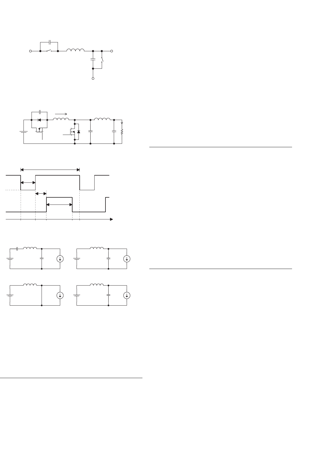
[22]. A constant-frequency
multi-resonant (CF-MR) switch is shown in Fig. 16.18. The
output voltage is regulated by controlling the on-time of
the two switches. This concept can be illustrated with the
buck converter as shown in Fig. 16.19, together with the
gate drive waveforms and operating stages. S
1
and S
2
are
turned on during the time when currents flow through the
anti-parallel diodes of S
1
and S
2
. This stage ends when S
2
is
turned off with ZVS. The first resonant stage is then started.
L
r
and C
S2
form the resonant circuit. A second resonant
stage begins. L
r
resonates with C
S1
and C
S2
. The voltage
across S
1
oscillates to zero. When I
Lr
becomes negative, S
1
will be turned on with ZVS. Then, L
r
resonates with C
S2
.
S
2
will be turned on when current flows through D
S2
.As
the output voltage is the average voltage across S
2
, output
voltage regulation is achieved by controlling the conduction
time of S
2
.
All switches in MRCs operate with ZVS, which reduces the
switching losses and switching noise and eliminates the oscil-
lation due to the parasitic effects of the components (such as
the junction capacitance of the diodes). However, all switches
are under high current and voltage stresses, resulting in an
increase in the conduction loss.
V
i
L L
F
S
C
S
D
S
C
D
D V
o
BUCK
V
i
L L
F
D
S
S C
S
D
C
D
V
o
BOOST
V
i
L
S
C
S
D
S
C
D
L
F
D
V
o
BUCK/BOOST
V
i
L
F
L
F
D
S
S C
S
C
D
D
L C
T
V
o
CUK
V
i
L
T
L
F
C
D
D
L C
T
S
C
S
D
S
V
o
ZETA
V
i
L
F
L
T
D
S
S C
S
D
C
D
L C
T
V
o
SEPIC
FIGURE 16.17 Use of the multi-resonant switch in conventional PWM
converters.
16 Resonant and Soft-switching Converters 421
C
s1
C
s2
L
S
1
S
2
FIGURE 16.18 Constant frequency multi-resonant switch.
V
i
C
f
L
L
f
R
L
i
L
S
1
S
2
C
s1
C
s2
(a)
T
S
T
OFF
T
ON
T
D
t
0
S2 DRIVE
WAVEFORM
tt
4
t
3
t
2
t
1
S1 DRIVE
WAVEFORM
(b)
LC
s1
C
s2
I
o
L
C
s2
I
o
[t0,t1] [t1,t2]
L
I
o
[t2,t3]
L
C
s2
I
o
[t3,t4]
(c)
FIGURE 16.19 Constant frequency buck MRC: (a) circuit schematics;
(b) gate drive waveforms; and (c) operating stages.
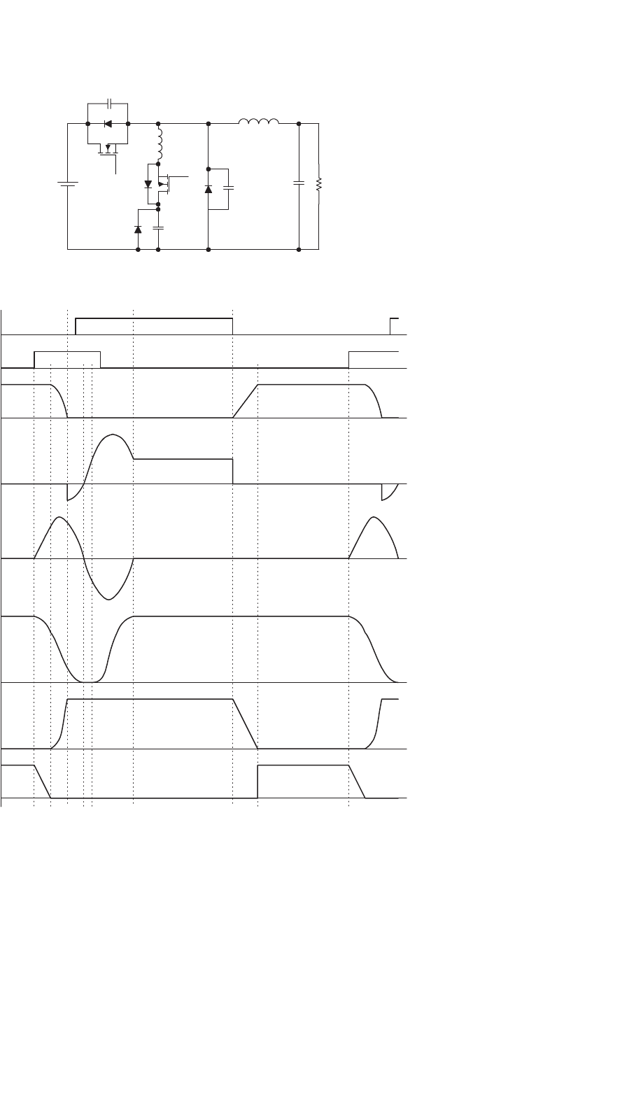
16.7 Zero-voltage-transition (ZVT)
Converters
By introducing a resonant circuit in parallel with the switches,
the converter can achieve ZVS for both power switch and
diode without significantly increasing their voltage and current
stresses [23]. Figure 16.20a shows a buck type ZVT-PWM
converter and Fig. 16.20b shows the associated waveforms.
The converter consists of a main switch S and an auxiliary
switch S
1
. It can be seen that the voltage and current wave-
forms of the switches are square-wave-like except during
turn-on and turn-off switching intervals, where ZVT takes
place. The main switch and the output diode are under ZVS
and are subjected to low voltage and current stresses. The
auxiliary switch is under ZCS, resulting in low switching loss.
The concept of ZVT can be extended to other PWM cir-
cuits by adding the resonant circuit. Some basic ZVT-PWM
converters are shown in Fig. 16.21.
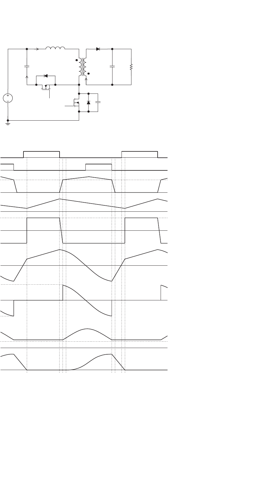
16.8 Non-dissipative Active Clamp
Network
The active-clamp circuit can utilize the transformer leakage
inductance energy and can minimize the the turn-off volt-
age stress in the isolated converters. The active clamp circuit
provides a means of achieving ZVS for the power switch and
reducing the rate of change of the diode’s reverse recovery
current. An example of a flyback converter with active clamp
is shown in Fig. 16.22a and the circuit waveforms are shown
in Fig. 16.22b. Clamping action is obtained by using a series
combination of an active switch (i.e. S
2
) and a large capacitor
so that the voltage across the main switch (i.e. S
1
) is clamped
to a minimum value. S
2
is turned on with ZVS. However,
S
2
is turned off with finite voltage and current, and has turn-
off switching loss. The clamp-mode ZVS-MRCs is discussed
in [24–26].
16.9 Load Resonant Converters
Load resonant converters (LRCs) have many distinct fea-
tures over conventional power converters. Due to the soft
commutation of the switches, no turn-off loss or stress is
present. LRCs are specially suitable for high-power appli-
cations because they allow high-frequency operation for
equipment size/weight reduction, without sacrificing the con-
version efficiency and imposing extra stress on the switches.
Basically, LRCs can be divided into three different configu-
rations, namely series resonant converters, parallel resonant
converters, and series–parallel resonant converters.
16.9.1 Series Resonant Converters
Series resonant converters (SRCs) have their load connected in
series with the resonant tank circuit, which is formed by L
r
and
C
r
[15, 27–29]. The half-bridge configuration is shown in
Fig. 16.23. When the resonant inductor current i
Lr
is positive,
it flows through T
1
if T
1
is on; otherwise it flows through the
diode D
2
. When i
Lr
is negative, it flows through T
2
if T
2
is on;
422 S. Y. Hui and H. S. H. Chung
V
i
C
o
L
f
R
S
S
1
C
d
L
r
C
r
D
1
C
D
D
(a)
t
0
t
5
t
4
t
3
t
2
t
1
t
0
t
7
t
6
I
o
V
i
2V
i
I
o
V
i
on
off
on
off
V
D
S
S
S1
I
S
V
C
r
I
Lr
V
D
I
D
(b)
FIGURE 16.20 Buck ZVT-PWM converter: (a) circuit schematics and (b) waveforms.
otherwise it flows through the diode D
1
. In the steady-state
symmetrical operation, both the active switches are operated in
a complementary manner. Depending on the ratio between the
switching frequency ω
S
and the converter resonant frequency
ω
r
, the converter has several possible operating modes.
A. Discontinuous Conduction Mode (DCM) with ω
S
< 0.5ω
r
Figure 16.24a shows the waveforms of i
Lr
and the resonant
capacitor voltage v
Cr
in this mode of operation. From 0 to
t
1
,T
1
conducts. From t
1
to t
2
, the current in T
1
reverses
its direction. The current flows through D
1
and back to the
16 Resonant and Soft-switching Converters 423
D
S
(a) Buck (b) Boost
D
S
(c) Buck-boost
D
S
D
S
(d) Cuk
(e) Sepic
D
S
D
S
(f) Zeta
FIGURE 16.21 Conventional ZVT-PWM converters.
supply source. From t
2
to t
3
, all switches are in the off state.
From t
3
to t
4
,T
2
conducts. From t
4
to t
5
, the current in T
2
reverses its direction. The current flows through D
2
and back
to the supply source. T
1
and T
2
are switched on under ZCS
condition and they are switched off under zero-current and
zero-voltage conditions. However, the switches are under high
current stress in this mode of operation and thus have higher
conduction loss.
B. Continuous Conduction Mode (CCM) with
0.5ω
r
<ω
S
<ω
r
Figure 16.24b shows the circuit waveforms. From 0 to t
1
,
i
Lr
transfers from D
2
to T
1
.T
1
is switched on with finite
switch current and voltage, resulting in turn-on switching loss.
Moreover, the diodes must have good reverse recovery charac-
teristics in order to reduce the reverse recovery current. From
t
1
to t
2
,D
1
conducts and T
1
is turned off softly with zero volt-
age and zero current. From t
2
to t
3
,T
2
is switched on with
finite switch current and voltage. At t
3
,T
2
is turned off softly
and D
2
conducts until t
4
.
C. Continuous Conduction Mode (CCM) with ω
r
<ω
S
Figure 16.24c shows the circuit waveforms. From 0 to t
1
, i
Lr
transfers from D
1
to T
1
. Thus, T
1
is switched on with zero
current and zero voltage. At t
1
,T
1
is switched off with finite
voltage and current, resulting in turn-off switching loss. From
t
1
to t
2
,D
2
conducts. From t
2
to t
3
,T
2
is switched on with zero
current and zero voltage. At t
3
,T
2
is switched off. i
Lr
transfers
from T
2
to D
1
. As the switches are turned on with ZVS, lossless
snubber capacitors can be added across the switches.
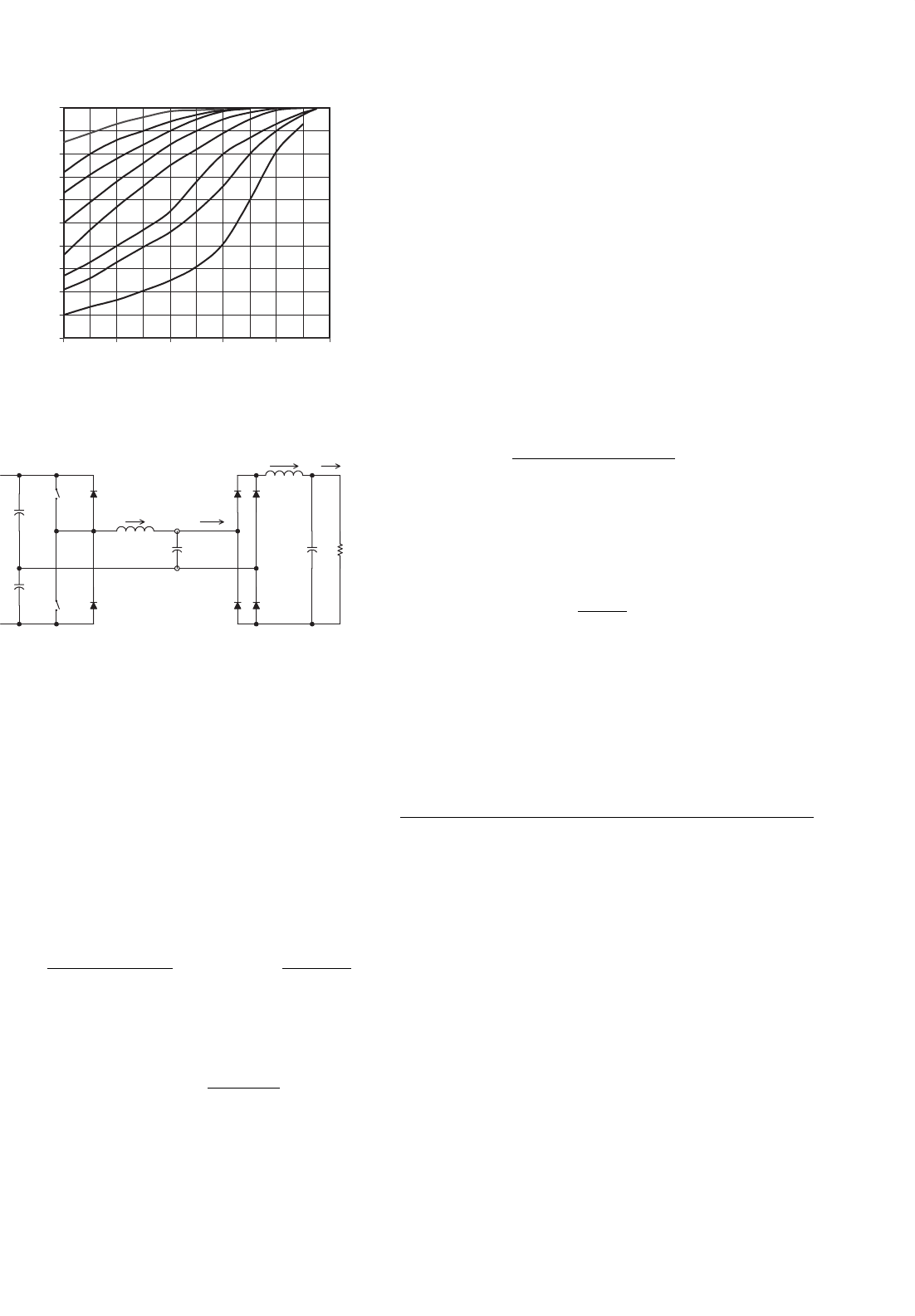
The following parameters are defined: voltage conversion
ratio M, characteristic impedance Z
r
, resonant frequency
f
r
, normalized load resistance r, normalized switching fre-
quency γ.
M = nV
o
/V
in
(16.2a)
Z
r
=
L
r
/C
r
(16.2b)
f
r
= 1/
2π
L
r
C
r
(16.2c)
r = n
2
R
L
/Z
r
(16.2d)
γ = f
s
/f
r
(16.2e)
M = 1
(γ −1/γ)
2
/(r
2
+1) (16.2f )
The relationships between M and γ for different value of r are
shown in Fig. 16.25. The boundary between CCM and DCM
424 S. Y. Hui and H. S. H. Chung
C
clamp
C
DS
L
leak
N:1
D
1
S
2
S
1
i
sec
i
Lleak
i
Cclamp
+
V
out
−
+
V
pri
−
−
V
C
+
V
in
(a)
t
0
t
7
t
6
t
5
t
4
t
3
t
1
t
2
S
1
0
S
2
0
V
S1
0
V
in
+NV
o
i
Lm
0
V
pri
0
V
in
−
NV
o
i
Lleak
0
i
Cclamp
0
i
S1,peak
−i
S1,peak
V
C
0
NV
o
i
D1
0
(b)
FIGURE 16.22 Active-clamp flyback converter: (a) circuit schematics and (b) circuit waveforms.
16 Resonant and Soft-switching Converters 425
T
1
T
2
Cr
L
r
C
f
R
D
1
D
2
B'
B
I
Lr
I
o
+
V
d
−
+
V
d
/2
−
+
V
d
/2
−
+ v
Cr
−
+
V
o
−
A
B
FIGURE 16.23 SRC half-bridge configuration.
is at r = 1.27γ. When the converter is operating in DCM and
0.2 <γ<0.5, M = 1.27 rγ.
The SRC has the following advantages. Transformer sat-
uration can be avoided since the series capacitor can block
the dc component. The light load efficiency is high because
the device current and conduction loss are low. However, the
major disadvantages are that there is difficulty in regulating
the output voltage under light load and no load conditions.
Moreover, the output dc filter capacitor has to carry high rip-
ple current, which could be a major problem in low-output
voltage and high-output current applications [29].
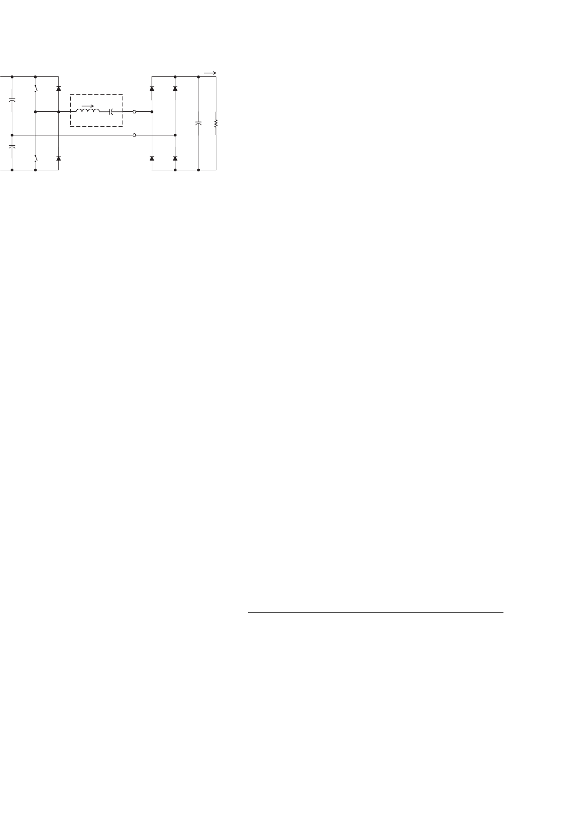
16.9.2 Parallel Resonant Converters
Parallel resonant converters (PRCs) have their load con-
nected in parallel with the resonant tank capacitor C
r
[27–30].
The half-bridge configuration is shown in Fig. 16.26. SRC
behaves as a current source, whereas the PRC acts as a voltage
source. For voltage regulation, PRC requires a smaller oper-
ating frequency range than the SRC to compensate for load
variation.
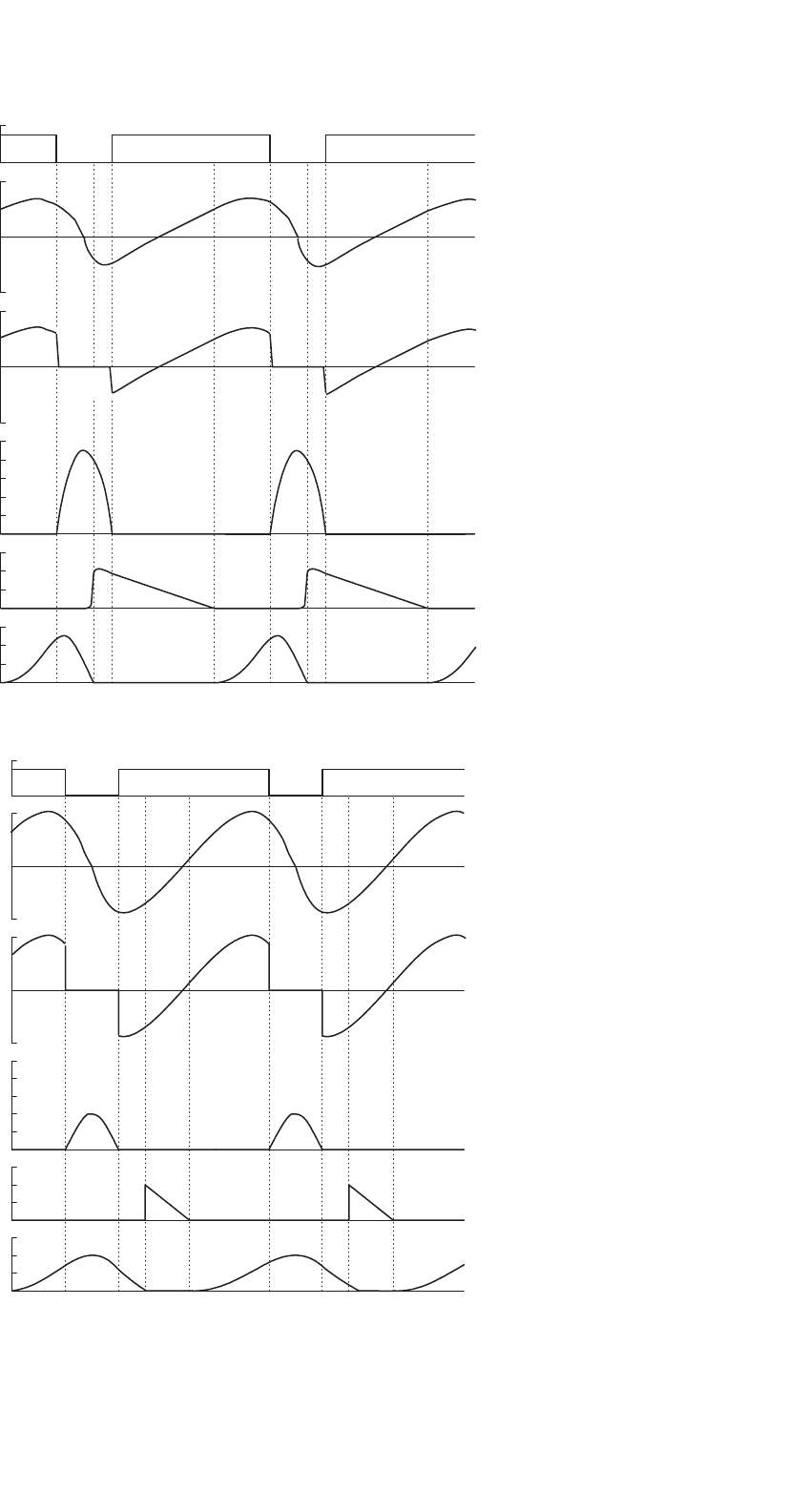
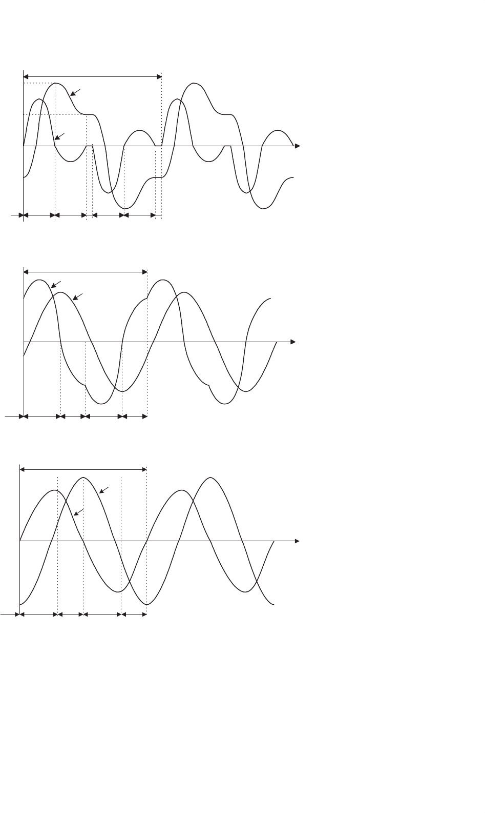
A. Discontinuous Conduction Mode (DCM)
The steady-state waveforms of the resonant inductor cur-
rent i
Lr
and the resonant capacitor voltage v
Cr
are shown in
Fig. 16.27a. Initially both i
Lr
and v
Cr
are zero. From 0 to t
2
,
T
1
conducts and is turned on with zero current. When i
Lr
is less than the output current I
o
, i
Lr
increases linearly from
0tot
1
and the output current circulates through the diode
bridge. From t
1
to t
3
, L
r
resonates with C
r
. Starting from t
2
,
i
Lr
reverses its direction and flows through D
1
.T
1
is then
turned off with zero current and zero voltage. From t
3
to t
4
,
v
Cr
decreases linearly due to the relatively constant value of I
o
.
At t
4
, when v
Cr
equals zero, the output current circulates
through the diode bridge again. Both i
Lr
and v
Cr
will stay
at zero for an interval. From t
5
to t
9
, the above operations will
be repeated for T
2
and D
2
. The output voltage is controlled by
adjusting the time interval of [t
4
, t
5
].
B. Continuous Conduction Mode ω
S
<ω
r
This mode is similar to the operation in the DCM, but with a
higher switching frequency. Both i
Lr
and v
Cr
become contin-
uous. The waveforms are shown in Fig. 16.27b. The switches
T
1
and T
2
are hard turned on with finite voltage and current
and are soft turned off with ZVS.
C. Continuous Conduction Mode ω
S
>ω
r
If the switching frequency is higher than ω
r
(Fig. 16.27c), the
anti-parallel diode of the switch will be turned on before the
switch is triggered. Thus, the switches are turned on with ZVS.
However, the switches are hard turned off with finite current
and voltage.
The parameters defined in Eq. (16.2) are applicable. The
relationships between M and γ for various values of r are
shown in Fig. 16.28. During the DCM (i.e. γ<0.5), M is
in linear relationship with γ. Output voltage regulation can
be achieved easily. The output voltage is independent on the
output current. The converter shows a good voltage source
characteristics. It is also possible to step up and step down the
input voltage.
The PRC has the advantages that the load can be short-
circuited and the circuit is suitable for low-output voltage,
high-output current applications. However, the major disad-
vantage of the PRC is the high device current. Moreover, since
the device current do not decrease with the load, the efficiency
drops with a decrease in the load [29].
16.9.3 Series–Parallel Resonant Converter
Series–Parallel Resonant Converter (SPRC) combines the
advantages of the SRC and PRC. The SPRC has an additional
capacitor or inductor connected in the resonant tank circuit
[29–31]. Figure 16.29a shows an LCC-type SPRC, in which
an additional capacitor is placed in series with the resonant
inductor. Figure 16.29b shows an LLC-type SPRC, in which
an additional inductor is connected in parallel with the reso-
nant capacitor in the SRC. However, there are many possible
combinations of the resonant tank circuit. Detailed analysis
can be found in [31].
16.10 Control Circuits for Resonant
Converters
Since the 1985s, various control integrated circuits (ICs) for
resonant converters have been developed. Some common ICs
for different converters are described in this section.
16.10.1 QRCs and MRCs
Output regulations in many resonant-type converters, such
as QRCs and MRCs, are achieved by controlling the
426 S. Y. Hui and H. S. H. Chung
1 cycle
T
1
180°
D
1
180°
T
2
D
2
None
None
2V
o
−2V
o
0
V
d
v
Cr
i
Lr
t
3
t
2
t
1
t
0
t
5
t
4
(a)
D
2
0
v
Cr
i
Lr
t
2
t
1
t
0
1 cycle
T
2
D
2
T
1
D
1
t
3
(b)
ω
0
t0
v
Cr
i
Lr
1 cycle
D
1
t
2
t
1
t
0
T
2
D
1
T
1
D
2
t
3
(c)
ω
0
t
ω
0
t
FIGURE 16.24 Circuit waveforms under different operating conditions: (a) ω
S
< 0.5 ω
r
; (b) 0.5 ω
r
<ω
S
<ω; and (c) ω
r
<ω
S
.
16 Resonant and Soft-switching Converters 427
0
0.1
0.2
0.3
0.4
0.5
0.6
0.7
0.8
0.9
1
0.5 0.6 0.7 0.8 0.9 1
γ
M
3
2.2
r=5
1.73
1.27
1
0.75
0.67
FIGURE 16.25 M vs γ in SRC.
T
1
T
2
L
r
C
f
R
D
1
D
2
B'
B
i
o
I
Lr
I
o
+
V
d
−
+
V
d
/2
−
+
V
d
/2
−
+
V
o
−
A
B
C
r
i
B'B
L
f
FIGURE 16.26 PRC half-bridge configuration.
switching frequency. ZCS applications require controlled
switch-on times while ZVS applications require con-
trolled switch-off times. The fundamental control blocks in
the IC include an error amplifier, voltage controlled oscillator
(VCO), one shot generator with a zero wave-crossing detection
comparator, and an output stage to drive the active switch.
Typical ICs include UC1861–UC1864 for ZVS applications
and UC 1865–UC 1868 for ZCS applications [32]. Figure 16.30
shows the controller block diagram of UC 1864.
The maximum and minimum switching frequencies (i.e.
f
max
and f
min
) are controlled by the resistors R
ange
and R
min
and the capacitor C
vco
. f
max
and f
min
can be expressed as
f
max
=
3.6
(R
ange
//R
min
)C
VCO
and f
min
=
3.6
R
min
C
VCO
(16.3)
The frequency range f is then equal to
f = f
max
−f
min
=
3.6
R
ange
C
VCO
(16.4)
The frequency range of the ICs is from 10 kHz to 1 MHz.
The output frequency of the oscillator is controlled by the error
amplifier (E/A) output. An example of a ZVS-MR forward
converter is shown in Fig. 16.31.
16.10.2 Phase-shifted, ZVT FB Circuit
The UCC3895 is a phase shift PWM controller that can gener-
ate a phase shifting pattern of one half-bridge with respect to
the other. The application diagram is shown in Fig. 16.32.
The four outputs “OUTA,” “OUTB,” “OUTC,” and
“OUTD” are used to drive the MOSFETs in the full-bridge.
The dead time between “OUTA” and “OUTB” is controlled by
“DELAB” and the dead time between “OUTC” and “OUTD”
is controlled by “DELCD.” Separate delays are provided for
the two half-bridges to accommodate differences in reso-
nant capacitor charging currents. The delay in each set is
approximated by
t
DELAY
=
25 ×10
−12
R
DEL
0.75(V
CS
−V
ADS
) +0.5
+25 ns (16.5)
where R
DEL
is the resistor value connected between “DELAB”
or “DELCD” to ground.
The oscillator period is determined by R
T
and C
T
.Itis
defined as
t
OSC
=
5R
T
C
T
48
+120 ns (16.6)
The maximum operating frequency is 1 MHz. The phase
shift between the two sets of signals is controlled by the
ramp voltage and the error amplifier output having a 7 MHz
bandwidth.
16.11 Extended-period Quasi-resonant
(EP-QR) Converters
Generally, resonant and quasi-resonant converters operate
with frequency control. The extended-period quasi-resonant
converters proposed by Barbi [33] offer a simple solution to
modify existing hard-switched converters into soft-switched
ones with constant frequency operation. This makes both
output filter design and control simple. Figure 16.33 shows
a standard hard-switched boost type PFC converter. In this
hard-switched circuit, the main switch SW1 could be sub-
ject to significant switching stress because the reverse recovery
current of the diode D
F
could be excessive when SW1 is
turned on. In practice, a small saturable inductor may be
added in series with the power diode D
F
in order to reduce the
di/dt of the reverse-recovery current. In addition, an optional
R–C snubber may be added across SW1 to reduce the dv/dt of
SW1. These extra reactance components can in fact be used
in the EP-QR circuit to achieve soft switching, as shown in
Fig. 16.34. The resonant components L
r
and C
r
are of small