Power electronic handbook
Подождите немного. Документ загружается.

1068 L. Morán and J. Dixon
39.2 Types of Active Power Filters
The technology of active power filter has been developed
during the past two decades reaching maturity for harmon-
ics compensation, reactive power, and voltage balance in ac
power networks. All active power filters are developed with
pulse width modulated (PWM) converters (current-source
or voltage-source inverters). The current-fed PWM inverter
bridge structure behaves as a non-sinusoidal current source to
meet the harmonic current requirement of the non-linear load.
It has a self-supported dc reactor that ensures the continuous
circulation of the dc current. They present good reliability,
but have important losses and require higher values of parallel
capacitor filters at the ac terminals to remove unwanted cur-
rent harmonics. Moreover, they cannot be used in multilevel
or multistep modes configurations to allow compensation in
higher power ratings.
The other converter used in active power filter topologies is
the PWM voltage-source inverter (PWM-VSI). This converter
Non-Linear
Load
AC Mains
I
S
I
L
I
C
Active Filter
V
dc
Non-Linear
Load
AC Mains
I
S
I
L
Active Filter
V
dc
V
AF
(a) (b)
Non-Linear
Load
AC Mains
I
S
I
L
Series Active
Filter
V
dc
V
AF
I
C
Shunt Passive
Filter
(c)
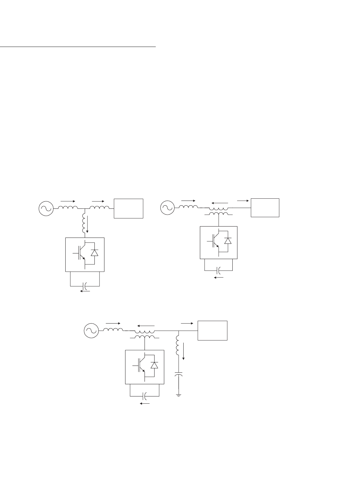
FIGURE 39.1 Active power filter topologies implemented with PWM-VSI: (a) shunt active power filter; (b) series active power filter; and (c) hybrid
active power filter.
is more convenient for active power filtering applications since
it is lighter, cheaper, and expandable to multilevel and multi-
step versions, to improve its performance for high power rating
compensation with lower switching frequencies. The PWM-
VSI has to be connected to the ac mains through coupling
reactors. An electrolytic capacitor keeps a dc voltage constant
and ripple free.
Active power filters can be classified based on the type
of converter, topology, control scheme, and compensation
characteristics. The most popular classification is based on
the topology such as shunt, series, or hybrid. The hybrid
configuration is a combination of passive and active compen-
sation. The different active power filter topologies are shown
in Fig. 39.1.
Shunt active power filters (Fig. 39.1a) are widely used to
compensate current harmonics, reactive power, and load cur-
rent unbalanced. It can also be used as a static var generator
in power system networks for stabilizing and improving volt-
age profile. Series active power filters (Fig. 39.1b) is connected
39 Active Filters 1069
before the load in series with the ac mains, through a coupling
transformer to eliminate voltage harmonics and to balance and
regulate the terminal voltage of the load or line. The hybrid
configuration is a combination of series active filter and pas-
sive shunt filter (Fig. 39.1c). This topology is very convenient
for the compensation of high power systems, because the rated
power of the active filter is significantly reduced (about 10% of
the load size), since the major part of the hybrid filter consists
of the passive shunt LC filter used to compensate lower-
order current harmonics and reactive power at fundamental
frequency.
Due to the operation constraint, shunt or series active power
filters can compensate only specific power quality problems.
Therefore, the selection of the type of active power filter to
improve power quality depends on the source of the problem
as can be seen in Table 39.1.
The principles of operation of shunt, series, and hybrid
active power filters are described in the following sections.
TABLE 39.1 Active filter solutions to power quality problems
Active filter
connection
Load on ac supply AC supply on load
Shunt Current harmonic filtering
Reactive current compensation
Current unbalance
Voltage flicker
Series Current harmonic filtering Voltage sag/swell
Reactive current compensation Voltage unbalance
Current unbalance Voltage distortion
Voltage flicker Voltage interruption
Voltage unbalance Voltage flicker
Voltage notching
39.3 Shunt Active Power Filters
Shunt active power filters compensate current harmonics by
injecting equal but opposite harmonic compensating current.
In this case, the shunt active power filter operates as a current
source injecting the harmonic components generated by the
load but phase shifted by 180
◦
. As a result, components of
harmonic currents contained in the load current are cancelled
by the effect of the active filter, and the source current remains
sinusoidal and in phase with the respective phase-to-neutral
voltage. This principle is applicable to any type of load con-
sidered as an harmonic source. Moreover, with an appropriate
control scheme, the active power filter can also compensate the
load power factor. In this way, the power distribution system
sees the non-linear load and the active power filter as an ideal
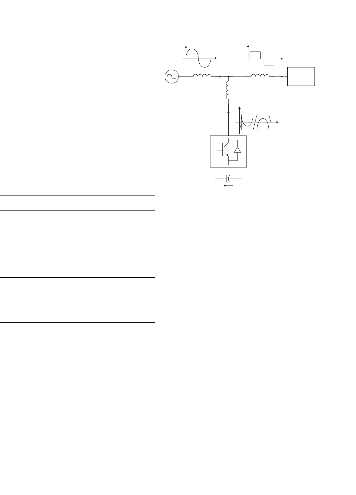
resistor. The compensation characteristics of the shunt active
power filter is shown in Fig. 39.2.
Non-Linear
Load
AC Mains
Active Filter
V
dc
I
S
I
L
Load CurrentSource Current
L
system
I
C
Compensation
Current
L
Load
L
coupling
FIGURE 39.2 Compensation characteristics of a shunt active power
filter.
39.3.1 Power Circuit Topologies
Shunt active power filters are normally implemented with
PWM-VSIs. In this type of application, the PWM-VSI oper-
ates as a current-controlled voltage source. Traditionally, two
level PWM-VSI have been used to implement such system
connected to the ac bus through a transformer. This type of
configuration is aimed to compensate non-linear load rated
in the medium power range (hundreds of kVA) due to semi-
conductors rated values limitations. However, in the last years
multilevel PWM-VSIs have been proposed to develop active
power filters for medium voltage and higher rated power appli-
cations. Also, active power filters implemented with multiple
VSIs connected in parallel to a dc bus but in series through a
transformer or in cascade has been proposed in the technical
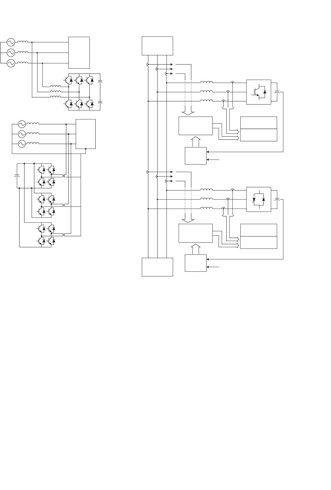
literature. The different power circuit topologies are shown in
Fig. 39.3.
The use of VSI connected in cascade is an interesting alter-
native to compensate high power non-linear loads. The use
of two PWM-VSI with different rated power allows the use
of different switching frequencies, reducing switching stresses,
and commutation losses in the overall compensation system.
The power circuit configuration of such a system is shown
in Fig. 39.4.
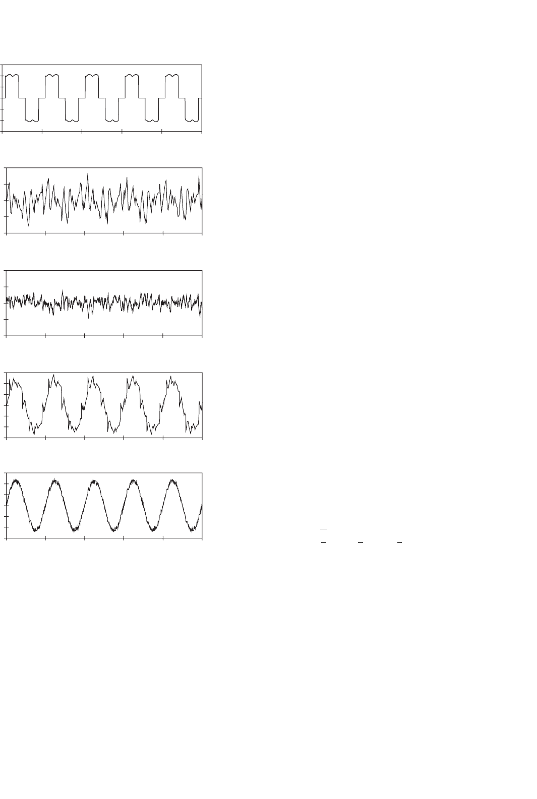
The VSI connected closer to the load compensates for the
displacement power factor and lower frequency current har-
monic components (Fig. 39.5b), while the second compensates
only high-frequency current harmonic components. The first
converter requires higher rated power than the second and
1070 L. Morán and J. Dixon
Non-
Linear
Load
(a)
Non-
Linear
Load
(b)
FIGURE 39.3 Shunt active power filter topologies implemented with
PWM-VSIs: (a) a three-phase PWM unit and (b) three single-phase units
in parallel to a common dc bus.
can operate at lower switching frequency. The compensation
characteristics of the cascade shunt active power filter is shown
in Fig. 39.5.
In recent years, there has been an increasing interest in using
multilevel inverters for high power energy conversion, espe-
cially for drives and reactive power compensation. The use
of neutral-point-clamped (NPC) inverters (Fig. 39.6) allows
equal voltage shearing of the series-connected semiconductors
in each phase. Basically, multilevel inverters have been devel-
oped for applications in medium voltage ac motor drives and
static var compensation. For these types of applications, the
output voltage of the multilevel inverter must be able to gen-
erate an almost sinusoidal output current. In order to generate
a near sinusoidal output current, the output voltage should not
contain low-frequency harmonic components.
However, for active power filter applications, the three-
level NPC inverter output voltage must be able to generate
an output current that follows the respective reference current
containing the harmonic and reactive component required by
Gating Signals
Generator
Current Control
System
AC Source
Current
Reference
Generator
Voltage
Control
DC Voltage Reference
Link
Inductor
PWM - VSI #2
Gating Signals
Generator
Current Control
System
Current
Reference
Generator
Voltage
Control
DC Voltage Reference
Link
Inductor
PWM - VSI #1
Non-Linear
Load
FIGURE 39.4 A shunt active power filter implemented with two PWM-
VSI connected in cascade.
the load. Current and voltage waveforms obtained for a shunt
active power filter implemented with a three-level NPC-VSI
are shown in Fig. 39.7.
39.3.2 Control Scheme
The control scheme of a shunt active power filter must cal-
culate the current reference waveform for each phase of the
inverter, maintain the dc voltage constant, and generate the
inverter gating signals. The block diagram of the control
scheme of a shunt active power filter is shown in Fig. 39.8.
The current reference circuit generates the reference cur-
rents required to compensate the load current harmonics and
reactive power, and also try to maintain constant the dc voltage
across the electrolytic capacitors. There are many possibilities
to implement this type of control, and the most popular of
them will be explained in this chapter. Also, the compensation
39 Active Filters 1071
−1,5
−1
−0,5
0
0,5
1
1,5
0 0,02 0,04 0,06 0,08 0,1
p.u.
(a)
0 0,02 0,04 0,06 0,08 0,1
(b)
0 0,02 0,04 0,06 0,08 0,1
(c)
−0,8
−0,4
0
0,4
0,8
p.u.
−0,8
−0,4
0
0,4
0,8
p.u.
−1,5
−1
−0,5
0
0,5
1
1,5
0 0,02 0,04 0,06 0,08 0,1
p.u.
(d)
0 0,02 0,04 0,06 0,08 0,1
(e)
−1,5
−1
−0,5
0
0,5
1
1,5
p.u.
FIGURE 39.5 Current waveforms of active power filter implemented
with two PWM-VSI in cascade: (a) load current waveform; (b) current
waveform generated by PWM-VSI no. 1; (c) current waveform generated
by PWM-VSI no. 2; (d) power system current waveform between the
two inverters (THD
i
= 13.7%); and (e) power system current waveform
(THD
i
= 4.5%).
effectiveness of an active power filter depends on its ability to
follow with a minimum error and time delay, the reference
signal calculated to compensate the distorted load current.
Finally, the dc voltage control unit must keep the total dc
bus voltage constant and equal to a given reference value. The
dc voltage control is achieved by adjusting the small amount
of real power absorbed by the inverter. This small amount
of real power is adjusted by changing the amplitude of the
fundamental component of the reference current.
39.3.2.1 Current Reference Generation
There are many possibilities to determine the reference current
required to compensate the non-linear load. Normally, shunt
active power filters are used to compensate the displacement
power factor and low-frequency current harmonics generated
by non-linear loads. One alternative to determine the current
reference required by the VSI is the use of the instantaneous
reactive power theory, proposed by Akagi [1], the other one is
to obtain current components in d–q or synchronous reference
frame [2], and the third one to force the system line current
to follow a perfectly sinusoidal template in phase with the
respective phase-to-neutral voltage.
39.3.2.1.1 Instantaneous Reactive Power Theory This con-
cept is very popular and useful for this type of application,
and basically consists of a variable transformation from the a,
b, c, reference frame of the instantaneous power, voltage, and
current signals to the α, β reference frame. The transforma-
tion equations from the a, b, c, reference frame to the α, β
coordinates can be derived from the phasor diagram shown in
Fig. 39.9.
The instantaneous values of voltages and currents in the α,
β coordinates can be obtained from the following equations:
v
α
v
β
=
[
A
]
·
v
a
v
b
v
c
i
α
i
β
=
[
A
]
·
i
a
i
b
i
c
(39.1)
where A is the transformation matrix, derived from Fig. 39.9
and is equal to
[
A
]
=
2
3
1 −1/2 −1/2
0
√
3/2 −
√
3/2
(39.2)
This transformation is valid if and only if v
a
(t) + v
b
(t) +
v
c
(t) is equal to zero, and also if the voltages are balanced
and sinusoidal. The instantaneous active and reactive power
in the α, β coordinates are calculated with the following
expressions:
p(t) = v
α
(t) · i
α
(t) + v
β
(t) · i
β
(t) (39.3)
q(t ) =−v
α
(t) · i
β
(t) + v
β
(t) · i
α
(t) (39.4)
It is evident that p(t) becomes equal to the conventional
instantaneous real power defined in the a, b, c reference frame.
1072 L. Morán and J. Dixon
Non-Linear
Load
AC Source
L
I
C
I
S
I
L
C1
C2
2V
DC
su1
su2
su3
sv1
sv2
sv3
su4 sv4
sw1
sw2
sw3
sw4
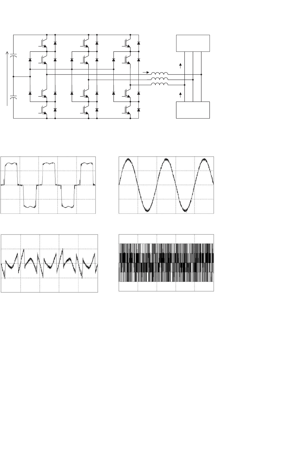
FIGURE 39.6 A shunt active power filter implemented with a three-level neutral point-clamped VSI.
(a)
i_La
linv vinv
200.00
100.00
0.00
−100.00
−200.00
200.00
100.00
0.00
−100.00
−200.00
i_La
200.00
100.00
0.00
−100.00
−200.00
0.00 10.00 20.00 30.00
Time (ms)
40.00 50.00
(b)
0.00 10.00 20.00 30.00
Time (ms)
40.00 50.00
(c)
0.00 10.00 20.00 30.00
Time (ms)
40.00 50.00
(d)
0.00
−1.50K
−1.00K
−0.50K
0.00K
0.50K
1.00K
1.50K
10.00 20.00 30.00
Time (ms)
40.00 50.00
FIGURE 39.7 Current and voltage waveforms for a shunt active power filter implemented with a three-level NPC-VSI: (a) load current;
(b) compensated system current (THD = 3.5%); (c) current generated by the shunt active power filter; and (d) inverter output voltage.
However, in order to define the instantaneous reactive power,
Akagi introduces a new instantaneous space vector defined by
expression (39.4) or by the vector equation:
q = v
α
xi
β
+v
β
xi
α
(39.5)
The vector q is perpendicular to the plane of α, β coordi-
nates, to be faced in compliance with a right-hand rule, v
α
is
perpendicular to i
β
, and v
β
is perpendicular to i
α
. The physical
meaning of the vector q is not “instantaneous power” because
of the product of the voltage in one phase and the current in
the other phase. On the contrary, v
α
i
α
and v
β
i
β
in Eq. (39.3)
obviously mean “instantaneous power” because of the product
of the voltage in one phase and the current in the same phase.
Akagi named the new electrical quantity defined in Eq. (39.5)
“instantaneous imaginary power,” which is represented by the
product of the instantaneous voltage and current in different
axes, but cannot be treated as a conventional quantity.
39 Active Filters 1073
Reference Current
Generator
Active, Reactive
and Harmonic
decomposition of
the Load Current
iar(t) ibr(t) icr(t)
12
Driver
Voltage Control
Unit
P*(t)
P
avg
Current Reference Generator
DC Voltage Control
Current Control and Gating Signals Generator
V
dc gen.
V
dc ref.
Gating Signals
Gen.
Current
Control
Unit
va(t) vb(t) vc(t)
va(t)
vb(t)
vc(t)
Ia
Load
(t) Ib
Load
(t) Ic
Load
(t)
Compensated
Current Component
dc Current Control
Component
Ia
Gen
(t)
Ib
Gen
(t)
Ic
Gen
(t)
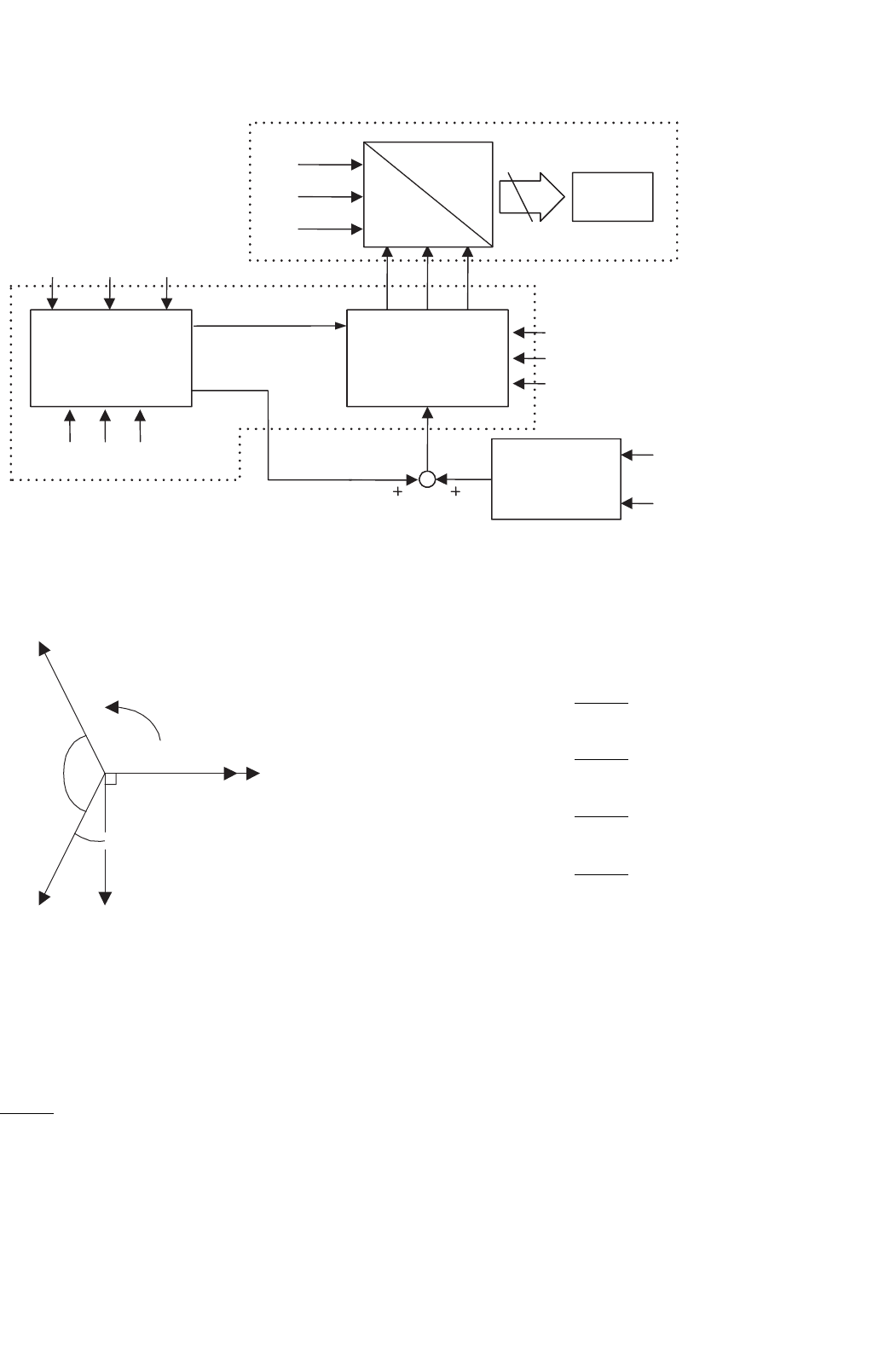
FIGURE 39.8 The block diagram of a shunt active power filter control scheme.
c
a
b
α
β
V
a
, i
a
V
α
, i
α
V
β
, i
β
V
b
, i
b
30°
120°
V
c
, i
c
ω t
FIGURE 39.9 Transformation diagram from the a, b, c reference frame
to the α, β coordinates.
The expression of the currents in the α–β plane, as a func-
tion of the instantaneous power is given by the following
equation:
i
α
i
β
=
1
v
2
α
+v
2
β
·
v
α
v
β
v
β
−v
α
·
p
0
+
v
α
v
β
v
β
−v
α
·
0
q
≡
i
αp
i
βp
+
i
αq
i
βq
(39.6)
and the different components of the currents in the α–β plane
are shown in the following expressions:
i
αp
=
v
α
p
v
2
α
+v
2
β
(39.7)
i
αq
=
v
β
q
v
2
α
+v
2
β
(39.8)
i
βp
=
v
β
p
v
2
α
+v
2
β
(39.9)
i
βq
=
−v
α
q
v
2
α
+v
2
β
(39.10)
From Eqs. (39.3) and (39.4), the values of p and q can
be expressed in terms of the dc components plus the ac
components, that is:
p =
¯
p +
˜
p (39.11)
q =¯q +˜q (39.12)
where,
¯
p dc component of the instantaneous power p, and is related
to the conventional fundamental active current.
˜
p is the ac component of the instantaneous power p, it does
not have average value, and is related to the harmonic
1074 L. Morán and J. Dixon
currents caused by the ac component of the instantaneous
real power.
¯q is the dc component of the imaginary instantaneous power
q, and is related to the reactive power generated by the
fundamental components of voltages and currents.
˜q is the ac component of the instantaneous imaginary power
q, and it is related to the harmonic currents caused by the
ac component of instantaneous reactive power.
In order to compensate reactive power (displacement power
factor) and current harmonics generated by non-linear loads,
the reference signal of the shunt active power filter must
include the values of
˜
p, ¯q, and ˜q. In this case the reference cur-
rents required by the shunt active power filters are calculated
with the following expression:
i
∗
c,α
i
∗
c,β
=
1
v
2
α
+v
2
β
·
v
α
v
β
v
β
−v
α
·
˜
p
L
¯q
L
+˜q
L
(39.13)
The final compensating currents including the zero
sequence components in a, b, c reference frame are the
following:
i
∗
c,a
i
∗
c,b
i
∗
c,c
=
2
3
·
1
√
2
10
1
√
2
−1
2
√
3
2
1
√
2
−1
2
−
√
3
2
·
−i
0
i
∗
c,α
i
∗
c,β
(39.14)
where the zero sequence current component i
0
is equal to 1/
√
3
(i
a
+ i
b
+ i
c
). The block diagram of the circuit required to
generate the reference currents defined in Eq. (39.14) is shown
in Fig. 39.10.
The advantage of instantaneous reactive power theory is that
real and reactive power associated with fundamental compo-
nents are dc quantities. These quantities can be extracted with a
low-pass filter. Since the signal to be extracted is dc, filtering of
the signal in the α–β reference frame is insensitive to any phase
a-b-c
to
α - β
α - β
to
a-b-c
a-b-c
to
α - β
l
aload
Van
Vbn
Vcn
laload
laload
Vα
Iα
Iβ
Vβ
P
and
Q
V
a
2
and V
b
2
P
Q
LPF
Q
ref
Pref
∆Vdc
lαref
and
l
βref
laref
lbref
lcref
V
a
2
V
b
2
lαref
lβref
FIGURE 39.10 The block diagram of the current reference generator using p–q theory.
shift errors introduced by the low-pass filter, improving com-
pensation characteristics of the active power filter. The same
advantage can be obtained by using the synchronous reference
frame method, proposed in [2]. In this case, transformation
from a, b, c axes to d–q synchronous reference frame is done.
Effects of the Low-pass Filter Design Characteristics in
Compensation Performance
A Butterworth filter is normally used due to the adequate
frequency response. A second-order filter offers an appropri-
ate relation between the transient response and the required
attenuation characteristic. Higher-order filters achieve bet-
ter filtering characteristic, but the settling time is increased.
Since the low-pass filter cannot eliminate completely the low-
frequency harmonic contained in the p and q signals, the shunt
active power filter cannot compensate the entire low-frequency
harmonic contained in the load current. Normally the cut-
off frequency is equal to 127 Hz with an attenuation factor of
15 dB for the first ac component to be eliminated, which means
an 82.2% attenuation of the fifth and seventh harmonic com-
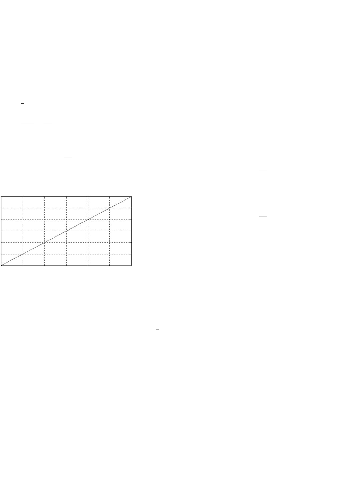
ponents (Fig. 39.11). The expression that relates the system line
current harmonic distortion with the LPF cut-off frequency
and load power factor is shown in Eq. (39.15).
THD
isys
=
∞
h=6k
1
(
f
n
/f
c
)
4
+1
((h
2
+1)/(h
2
−1))−(1/(h
2
−1))cos(2ϕ)
cos(ϕ)
(39.15)
with k = 1, 2, 3, ... and f
h
is the frequency of the harmonic
component of order h, and f
c
is the LPF cut-off frequency.
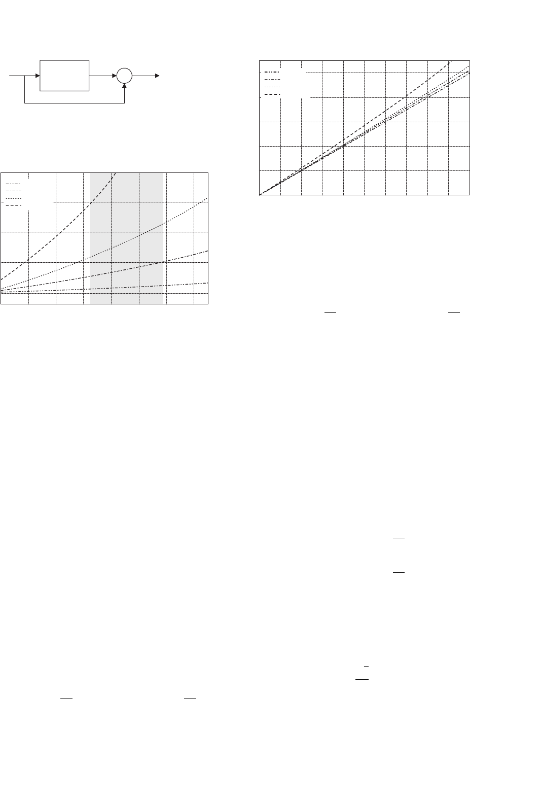
Figure 39.12 shows the total harmonic distortion (THD) in
the line currents introduced by the second-order Butterworth
filtering characteristics, as a function of the cut-off frequency,
and considering a 50 Hz ac mains frequency. The harmonic
distortion of the compensated line current depends on the
39 Active Filters 1075
Low-pass
filter
+
+
p
AC
−
p
FIGURE 39.11 The low-pass filter block diagram used to extract the ac
component of p.
40 60 80 100 120 140 160 180
0
5
10
15
20
Cut-off frequency
THDi [%]
PF = 1
PF = 0.8
PF = 0.5
PF = 0.2
FIGURE 39.12 Harmonic distortion of the compensated line current as
a function of the low-pass filter cut-off frequency. PF = cos(ϕ).
load displacement power factor, as shown in Eq. (39.15). If the
cut-off frequency of the low-pass filter is changed, the active
power filter compensation performance is affected as well as
the transient response of the control scheme.
Effects of the Supply Voltage Distortion in Compensation
Performance
One of the most important characteristics of the instantaneous
imaginary power concept is that in order to obtain the current
reference signal required to compensate reactive and harmonic
current components, the system phase-to-neutral voltages are
used. In general, purely sinusoidal voltages are considered in
previously reported analysis. In case voltage is purely sinu-
soidal, the dc component of p and q in the α–β plane are
related with the fundamental components in the real a, b, c
reference system. This is not the case if the system voltages are
distorted or unbalanced, as it is demonstrated below.
It is assumed that the supply voltages have harmonic
distortion, and these are represented by:
v
a
(
t
)
= V
1
cos
(
ωt
)
+V
h
cos
[
h
(
ωt −δ
h
)
]
v
b
(
t
)
= V
1
cos
ωt −
2π
3
+V
h
cos
h
ωt −δ
h
−
2π
3
0
2
4
6
8
10
THDv
[
%
]
THDi [%]
PF = 1
PF = 0.8
PF = 0.5
PF = 0.2
51234 6789010
FIGURE 39.13 Harmonic distortion in the compensated line current as
a function of the harmonic distortion in the system voltages. PF = cos(ϕ).
v
c
(
t
)
= V
1
cos
ωt +
2π
3
+V
h
cos
h
ωt −δ
h
+
2π
3
(39.16)
Since the harmonic voltage component introduces a dc
component in p and q, compensation performance of the
shunt active power filter is reduced, as shown in Fig. 39.13.
The larger the harmonic distortion in the system voltage is,
the active power filter performance is more affected.
Effects of the Supply Voltage Unbalance in Compensation
Performance
Voltage unbalance also affects the active power filter com-
pensation performance. In this analysis, the phase-to-neutral
voltages of the ac supply are equal to:
v
a
(
t
)
= V
1
cos
(
ωt
)
v
b
(
t
)
= V
1
(
1 +m
)
cos
ωt −
2π
3
v
c
(
t
)
= V
1
(
1 −m
)
cos
ωt +
2π
3
(39.17)
with 0 < m < 1.
If the low-pass filter is considered as ideal, and the active
filter follows exactly the current references, the compensated
supply current (phase a) is:
i
Sa
= I
1
cos
(
ϕ
)
cos
(
ωt
)
+
√
3
3
m
[
I
1
sin
(
ϕ
)
cos
(
3ωt
)
+I
1
cos
(
3ωt −ϕ
)
]
(39.18)
1076 L. Morán and J. Dixon
In this case, the active power filter is not able to fully
compensate the system line current, since compensation
performance depends on the voltage unbalance magnitude.
If the unbalance is defined as a function of the positive and
negative sequence component as:
V
a1
=
1
3
V
a
+a
2
V
b
+aV
c
V
a2
=
1
3
V
a
+aV
b
+a
2
V
c
, a = 1∠120
◦
Unbalance =
|
V
a2
|
|
V
a1
|
=
√
3
3
m
(39.19)
The harmonic distortion is equal to:
THD
i
=
√
3
3
m (39.20)
The relation between line current harmonic distortion and
voltage unbalance is shown in Fig. 39.14.
6
5
4
THDi [%]
3
2
1
0
012 3
Desb. [%]
456
FIGURE 39.14 Harmonic distortion in the compensated line current as
a function of the system voltages unbalance.
Effects of the Time Delay Introduced by the DSP in
Compensation Performance
If a DSP is used to derive the reference generation signals,
a time delay, T, associated with the processing time is intro-
duced in the calculation of the reference signals. Considering
a simultaneous sampling, the ac mains compensated line
current with an ideal low-pass filter in the control scheme
(phase a) is:
i
Sa
= I
1
cos
(
ωt
)
[
cos
(
ϕ
)
+sin
(
ωT
)
]
+V
DC
cos
(
ωt
)
+
∞
n=2k−1
I
n
[
1 −cos
(
nωT
)
]
cos
[
n
(
ωt −ϕ
)
]
+
∞
n=2k−1
I
n
sin
(
nωT
)
sin
[
n
(
ωt −ϕ
)
]
(39.21)
The time delay introduced by the DSP affects the compen-
sation performance, especially when fast changes are present
in the load current. Nevertheless, when T is small (T > 50 µs),
the effect in compensation performance is negligible.
In four-wire systems, unbalances in the load current also
affect the generation of the adequate current reference signal
that will assure high performance active power filter com-
pensation. This assumption can be proved by considering the
following load currents:
i
La
= I
1
cos
(
ωt −ϕ
)
+
∞
n=2k−1
I
n
cos
[
n
(
ωt −ϕ
)
]
i
Lb
= I
1
(
1 +l
)
cos
ωt −ϕ −
2π
3
+
∞
n=2k−1
I
n
(
1 +l
)
cos
n
ωt −ϕ −
2π
3
i
Lc
= I
1
(
1 −l
)
cos
ωt −ϕ +
2π
3
+
∞
n=2k−1
I
n
(
1 −l
)
cos
n
ωt −ϕ +
2π
3
i
LN
= i
La
+i
Lb
+i
Lc
(39.22)
with 0 < l < 1, k = 1, 2, 3, ...
Equation (39.23) shows the presence of low-frequency even
harmonics in the active power expression introduced by the
load current unbalanced. These low frequency current com-
ponents forces to reduce the cut-off frequency of the low-pass
filter, close to 100 Hz, which affects the transient response of
the active power filter.
p =
3
2
V
1
I
1
cos
(
ϕ
)
+
∞
n=2k−1
I
n
cos
[
(
n +1
)
ωt −nϕ
]
+
∞
m=2k−1
I
m
cos
[
(
m −1
)
ωt −mϕ
]
with k = 1, 2, 3, ...
(39.23)
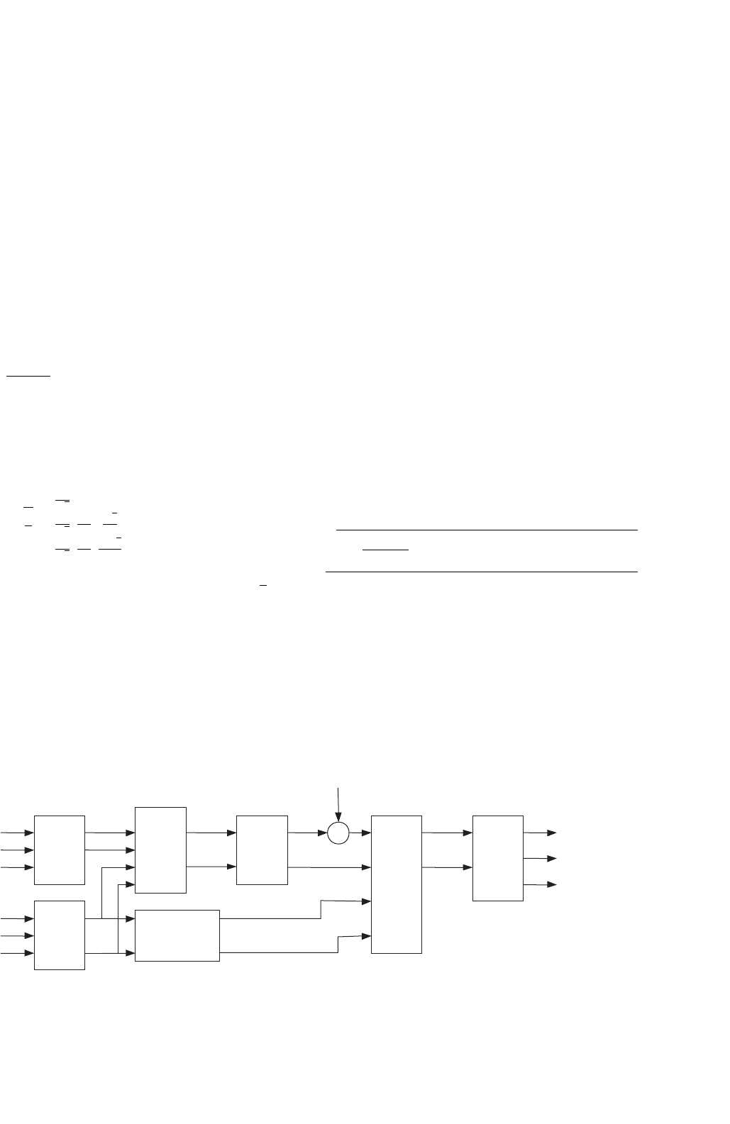
39.3.2.1.2 Synchronous Reference Frame Algorithm The
block diagram of a current reference generator that uses the
synchronous reference frame algorithm is shown in Fig. 39.15.
In this case, the real currents are transformed into a
synchronous reference frame [2]. The reference frame is syn-
chronized with the ac mains voltage, and is rotating at the
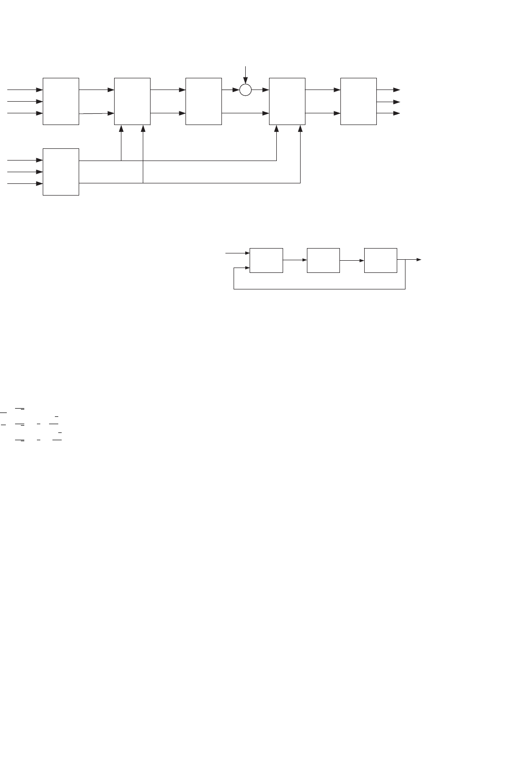
39 Active Filters 1077
PLL
cos(θ)
sin(θ)
I
aload
Ibload
Icload
Van
Vbn
Vcn
a-b-c
to
α - β
α - β
to
d - q
I
d
Iq
LPF
I
dref
∆V
dc
+
+
d - q
to
α - β
I
qref I
βref
I
αref
α - β
to
a-b-c
I
aref
Ibref
Icref
Iα
Iβ
FIGURE 39.15 The circuit block diagram required to obtain current reference waveforms using the synchronous reference frame theory.
same frequency. The transformation is defined by:
i
d
i
q
=
cos
(
ωt
)
sin
(
ωt
)
sin
(
ωt
)
cos
(
ωt
)
i
α
i
β
(39.24)
As for the instantaneous reactive power theory, d and q
terms are composed by a dc and multiple ac components,
such as i
d
= i
ddc
+i
dac
and i
q
= i
qdc
+i
qac
. The compensation
reference signals are obtained from the following expressions:
i
dref
=−i
dac
and i
qref
=−i
qdc
− i
qac
. The compensated cur-
rents generated by the shunt active power filter are obtained
from Eq. (39.25).
i
aref
i
bref
i
cref
=
2
3
1
√
2
10
1
√
2
−
1
2
√
3
2
1
√
2
−
1
2
−
√
3
2
−10 0
0 cos
(
ωt
)
−sin
(
ωt
)
0 sin
(
ωt
)
cos
(
ωt
)
i
0
i
dref
i
qref
(39.25)
One of the most important characteristics of this algorithm
is that the reference currents are obtained directly from the
loads currents without considering the source voltages. This is
an important advantage since the generation of the reference
signals is not affected by voltage unbalance or voltage distor-
tion, therefore increasing the compensation robustness and
performance. However, in order to transform from the α–β
plane to the d–q synchronous reference frame, sine and cosine
signals synchronized with the respective phase-to-neutral volt-
ages are required. A phase-locked loop (PLL) per each phase,
as the one shown in Fig. 39.16 must be used.
Since the algorithm used to obtain the reference current
presents the same mathematical procedure and operations that
the ones required in the instantaneous reactive power concept,
the effects introduced by the filter and DSP time delay are sim-
ilar. Unbalanced load currents generate a different harmonic
spectrum in the synchronous reference frame, and low-order
harmonic components appear in the reference signal. In order
Phase
Detector
Low-Pass
Filter
Voltage
Controlled
Oscillator
Input Signal
Output Signal
FIGURE 39.16 The PLL circuit block diagram.
to separate these uncharacteristic low-frequency current com-
ponents, the cut-off frequency of the low-pass filter must be
reduced.
39.3.2.1.3 Peak Detection Method There are other possi-
bilities to generate the current reference signal required to
compensate reactive power and current harmonics. Basically,
all the different schemes try to obtain the current refer-
ence signals that include the reactive components required
to compensate the displacement power factor and the cur-
rent harmonics generated by the non-linear load. Figure 39.17
shows another scheme used to generate the current reference
signals required by a shunt active power filter. In this case,
the ac current generated by the inverter is forced to follow
the reference signal obtained from the current reference gen-
erator. In this circuit, the distorted load current is filtered,
extracting the fundamental component, i
l1
. The band-pass fil-
ter is tuned at the fundamental frequency (50 or 60 Hz), so
that the gain attenuation introduced in the filter output sig-
nal is zero and the phase-shift angle is 180
◦
. Thus, the filter
output current is exactly equal to the fundamental component
of the load current but phase shifted by 180
◦
. If the load cur-
rent is added to the fundamental current component obtained
from the second-order band-pass filter, the reference current
waveform required to compensate only harmonic distortion is
obtained. In order to provide the reactive power required by
the load, the current signal obtained from the second-order
band-pass filter I
l1
is synchronized with the respective phase-
to-neutral source voltage (see Fig. 39.17) so that the inverter ac
output current is forced to lead the respective inverter output