Power electronic handbook
Подождите немного. Документ загружается.

1078 L. Morán and J. Dixon
Second
Order Filter
(50 or 60
Hz)
Peak
Value
+
Load
Current
Dc Reference
Voltage
−
Voltage
Error
Voltage
Controller
−
+
Dc Generated
Voltage
x
Sinusoidal
Waveform
(EPROM)
Synchronization
Signal with
System Voltage
Load
Current
+
−
i
l1
i
l1s
Current Reference Generator Dc Control Unit
Current
Controller
Reference
Current
Generated
Current
+
−
Gating Signals
Generator
Current Error
Current Control Unit
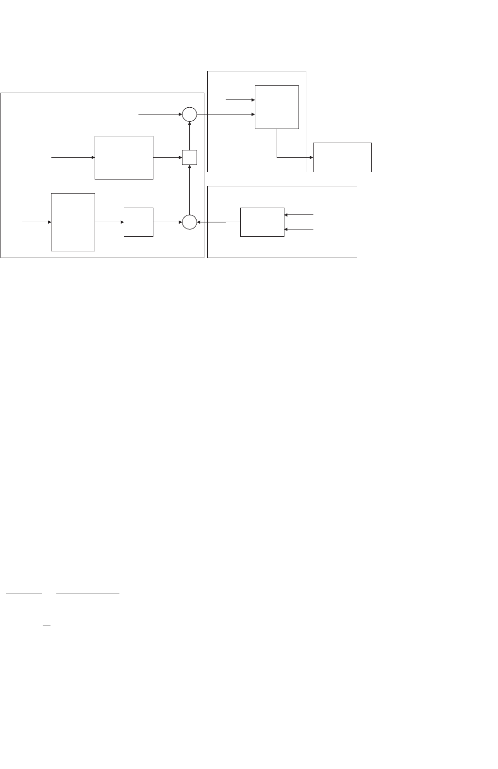
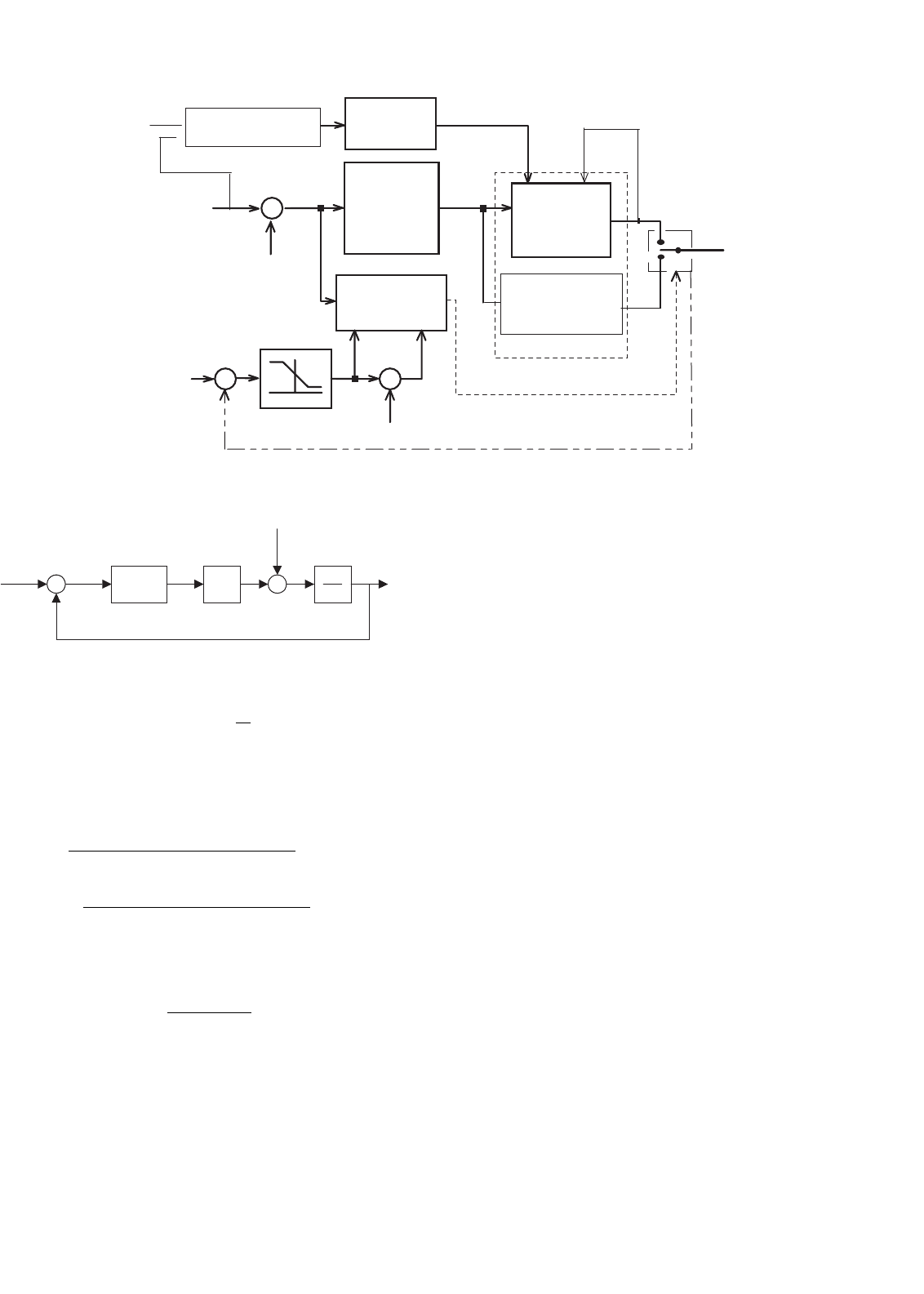
FIGURE 39.17 The block diagram of an active power filter control scheme that does not use the instantaneous reactive power concept.
voltage, thereby generating the required reactive power and
absorbing the real power necessary to supply the switching
losses and also to maintain the dc voltage constant.
The real power absorbed by the inverter is controlled by
adjusting the amplitude of the fundamental current reference
waveform, I
l1
, obtained from the reference current genera-
tor. The amplitude of this sinusoidal waveform is equal to the
amplitude of the fundamental component of the load cur-
rent plus or minus the error signal obtained from the dc
voltage control unit. In this way, the current signal allows
the inverter to supply the current harmonic components, the
reactive power required by the load, and to absorb the small
amount of active power necessary to cover the switching losses
and to keep the dc voltage constant (Fig. 39.18).
The main characteristic of this method is the direct deriva-
tion of the compensating component from the load current,
without the use of any reference frame transformation [1, 2].
Nevertheless, this technique presents a low frequency oscil-
lation problem in the active power filter dc bus voltage. To
improve this technique, a modification of the previous scheme
(Fig. 39.17) is shown in Fig. 39.19. The scheme is necessary for
each phase. The expression for i
Ma
is:
i
Ma
=
I
1
cos
(
ϕ
)
2
+
I
1
cos
(
2ωt −ϕ
)
2
+
∞
n=2k−1
I
n
2
cos
[
(
n −1
)
ωt −nϕ
]
+cos
[
(
n +1
)
ωt −nϕ
]
(39.26)
with k = 1, 2, 3, ...
Figure 39.20 shows the current harmonic distortion intro-
duced by the low-pass filter used in the control scheme and
the associated cut-off frequency. The current distortion of
the compensated current depends on the phase angle of the
fundamental load current component.
The supply voltage has no effect on the reference current
generation. Synchronization with the ac mains voltage is the
important issue in this scheme as well as in the synchronous
reference frame theory. Unbalanced loads do not affect the
reference generation. Nevertheless, the method cannot achieve
active power balance in four-wire systems. The control circuit
implementation of the peak detection method is simple and
does not require complex calculation, so the processing time
on a DSP is lower than the required in the two previous imple-
mentations, (T < 10 µs). The use of this method minimizes
the distortion introduced on current harmonics.
Technical Comparison of the Three Different Techniques
In order to validate the effectiveness of the proposed analy-
sis, a common industrial system is considered. The results are
obtained using the previous equations and Matlab simulations
results. The DSP delay introduced is using the processing time
according the DSP ADSP2187. The parameters considered are:
THD
iL
= 29%
THD
V
= 5%
cos
(
ϕ
)
= 0.87
Unbalance = 3%
39 Active Filters 1079
(a) (b)
2.0V
i
1s
i
load
i
11
i
1s
- i
load
0V
−2.0V
0s 10ms 20ms 30ms 40ms 0s 10ms 20ms 30ms 40ms
2.0V
0V
Fundamental
component
−2.0V
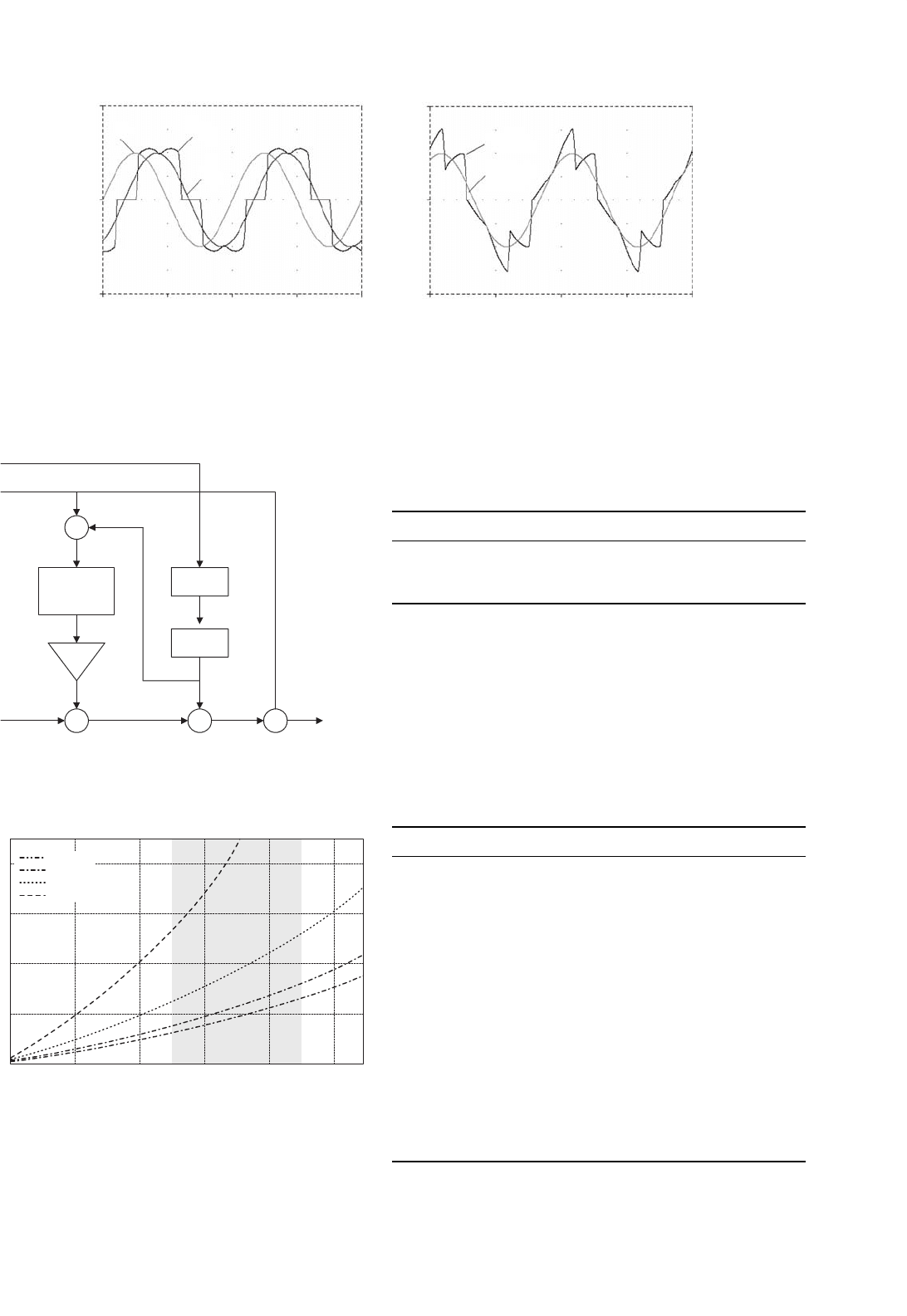
FIGURE 39.18 The procedure for the generation of the current reference waveform: (a) the load current i
load
, its fundamental component, i
l1
,
and the fundamental current component synchronized with the respective phase-to-neutral source voltage, i
ls
and (b) the synchronized fundamental
current signal minus the load current, i
ls
− i
load
, and its fundamental component.
Low-Pass
Filter
i
L
g = 2
PLL
cos (ωt )
x
x++
v
f
i*
C
+
+
+
−
i
M
FIGURE 39.19 Modified version of the original peak detection method.
4 8 12 16 20 24
0
2
4
Cut-off frequency
THDi [%]
6
8
PF = 1
PF = 0.8
PF = 0.5
PF = 0.2
FIGURE 39.20 Harmonic distortion of the system line current as a
function of the cut-off frequency of the low-pass filter and the load
displacement power factor.
Table 39.2 shows the numeric results:
TABLE 39.2 Results of the considered case
Technique THD
iS
[%] FP Transient delay t
d
[ms]
PQ 8.2 0.99 8.1
DQ 3.1 0.99 8.1
DPVM 2.3 0.99 56.8
Table 39.3 shows a comparison of the three different tech-
niques analyzed. The effects of the non-ideal conditions are
described for each technique.
In conclusion, it can be mentioned that the compensa-
tion performance of the different techniques is similar under
TABLE 39.3 Comparison of the techniques
Parameter PQ SRF PDM
Load PF required to
achieve full
compensation
PF > 0.3 PF > 0.3 PF > 0.2
Harmonic distortion
voltage effect on the
compensated current.
THD
i
≈ THD
v
00
Unbalanced voltage effect THD
i
≈
Unbalance
00
Dynamic response under
load changes (in
function of f
c
,
t
d
= 5τ )
Fast (load
balanced)
Fast(load
balanced)
Slow
Capability of load balance Yes (It is
necessary to
reduce cut-off
frequency f
c
)
Yes (It is
necessary to
reduce cut-off
frequency f
c
)
No
DSP delay time
introduced
Minimum Minimum ≈ 0
1080 L. Morán and J. Dixon
ideal conditions, but under the presence of unbalanced and
voltage distortion, the synchronous reference frame algorithm
presents the best performance, since it is insensitive to volt-
age perturbations. It is fundamental to consider adequately the
cut-off frequency in the filter used to extract the ac compo-
nent in the different techniques. If the frequency is changed,
the compensation performance is affected as well as the tran-
sient response of the control scheme. In four-wire systems,
unbalance in the load current also affects the generations of
the adequate current reference. Unbalanced load currents gen-
erate a different harmonic spectrum in the dc reference frame,
and low-order harmonic components appear in the reference
signal; then the cut-off frequency of the filter must be reduced.
39.3.2.2 Current Modulator
The effectiveness of an active power filter depends basi-
cally on the design characteristics of the current controller,
the method implemented to generate the reference template
and the modulation technique used. Most of the modulation
techniques used in active power filters are based on PWM
strategies. In this chapter, four of these methods, whose char-
acteristics are their simplicity and effectiveness, are analyzed:
periodical sampling control, hysteresis band control, triangu-
lar carrier control, and vector control. The first three methods
have been tested with different waveform templates sinu-
soidal, quasisquare, and rectifier compensation current and
were compared in terms of the harmonic content and distor-
tion at the same switching frequency [3]. The analysis shows
that for sinusoidal current generation the best method is tri-
angular carrier, followed by hysteresis band and periodical
sampling. For other types of references, however, one strat-
egy may be better than the others. Also it was shown that each
control method is affected in a different way by the switching
time delays present in the driving circuitry and in the power
semiconductors.
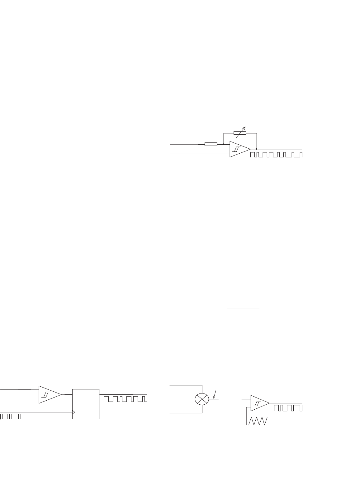
39.3.2.2.1 Periodical Sampling The periodical sampling
method switches the power transistors of the converter during
the transitions of a square wave clock of fixed frequency (the
sampling frequency). As shown in Fig. 39.21, this type of con-
trol is very simple to implement since it requires a comparator
and a D-type flip-flop per phase. The main advantage of this
QD
flip-flop
CLK
+
I_line
I_ref
PWM
sampling clock
−
FIGURE 39.21 Control modulator block for periodical sampling
method.
method is that the minimum time between switching transi-
tions is limited to the period of the sampling clock. However,
the actual switching frequency is not clearly defined.
39.3.2.2.2 Hysteresis band The hysteresis band method
switches the transistors when the current error exceeds a fixed
magnitude: the hysteresis band. As can be seen in Fig. 39.22,
this type of control needs a single comparator with hystere-
sis per phase. In this case the switching frequency is not
determined, but it can be estimated.
hysteresis band adjust
PWM
I_line
I_ref
+
−
FIGURE 39.22 Control modulator block for hysteresis band.
39.3.2.2.3 Triangular Carrier The triangular carrier method,
shown in Fig. 39.23, compares the current error with fixed
amplitude and fixed frequency triangular wave (the triangular
carrier). The error is processed through a proportional-
integral (PI) gain stage before the comparison with the tri-
angular carrier takes place. As can be seen, this control scheme
is more complex than the periodical sampling and hysteresis
band. The values for the PI control gain k
p
and k
i
deter-
mine the transient response and steady-state error of the
triangular carrier method. It was found empirically that the
values for k
p
and k
i
shown in Eqs. (39.27) and (39.28) give a
good dynamic performance under transient and steady-state
operating conditions.
k
∗
p
=
(
L +L
o
)
·ω
c
2V
dc
(39.27)
k
∗
i
= ω
c
k
∗
p
(39.28)
where L+L
o
is the total series inductance seen by the converter,
ω
c
is the triangular carrier frequency, whose amplitude is one
volt peak-peak, and V
dc
is the dc supply voltage of the inverter.
kp + ki/s
+
−
PWM
V_tri
I_line
I_ref
I_err
+
−
FIGURE 39.23 Control modulator block for triangular carrier method.
39 Active Filters 1081
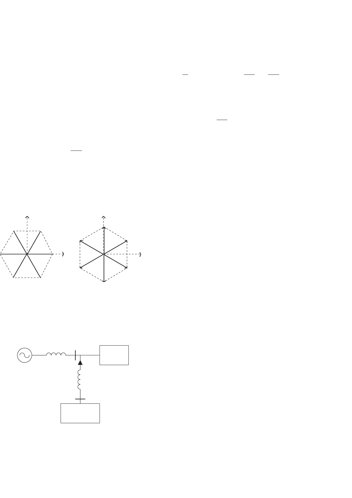
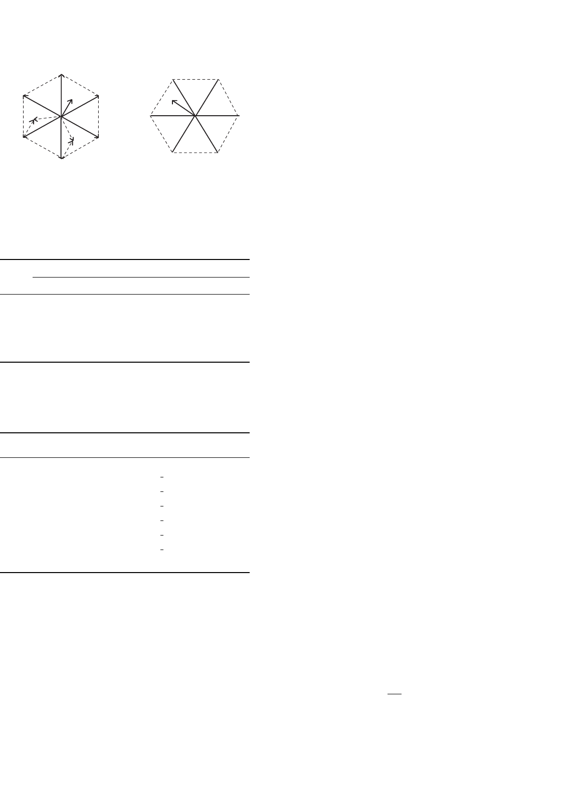
39.3.2.2.4 Vector Control Technique This current control
technique proposed in [4] divides the α–β reference frame
of currents and voltages in six regions, phase shifted by 30
◦
(Fig. 39.24), identifies the region where the current vector error
i is located, and selects the inverter output voltage vector V
inv
that will force i to change in the opposite direction, keeping
the inverter output current close to the reference signal.
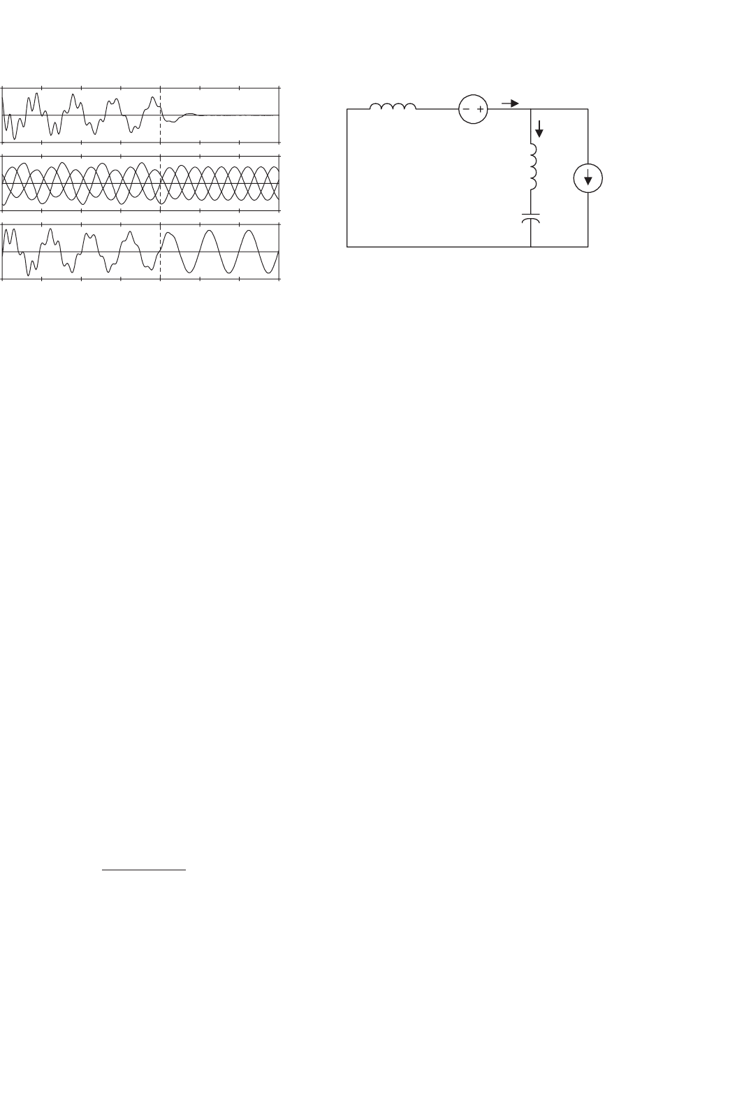
Figure 39.25 shows the single-phase equivalent circuit of the
shunt active power filter connected to a non-linear load and
to the power supply.
The equation that relates the active power filter currents and
voltages is obtained by applying Kirchhoff law to the equivalent
circuit shown in Fig. 39.25:
V
inv
= L
di
gen
dt
+E
0
(39.29)
The current error vector i is defined by the following
expression:
i = i
ref
−i
gen
(39.30)
α
β
1
2
3
4
5
6
V
1
V
2
V
3
V
4
V
5
V
6
α
β
I
II
IIIIV
V
VI
(a)
(b)
FIGURE 39.24 The hexagons defined in the α–β reference frame by the
current control scheme: (a) the hexagon defined by the inverter output
current vector and (b) the hexagon defined by the inverter output voltage
vector.
Active Power
Filter
Non-linear
Load
Power
Supply
L
s
L
L
V
inv
E
0
I
gen
FIGURE 39.25 The single-phase equivalent circuit of a shunt active
power filter connected to the power system.
where i
ref
represents the inverter reference current vector
defined by the instantaneous reactive power concept. By
replacing Eq. (39.30) in Eq. (39.29):
V
inv
= L
d
dt
(i
ref
−i) +E
0
⇒ L
di
dt
= L
di
ref
dt
+E
0
−V
inv
(39.31)
If E = L(di
ref
/dt) + E
0
then Eq. (39.31) becomes
L
di
dt
= E − V
inv
(39.32)
Equation (39.32) represents the active power filter state
equation and shows that the current error vector variation
di/dt is defined by the difference between the fictitious volt-
age vector E and the inverter output voltage vector V
inv
.In
order to keep di/dt close to zero, V
inv
must be selected
near E
0
.
The selection of the inverters’ gating signals is defined by
the region in which i is located and by its amplitude. In
order to improve the current control accuracy and associate
time response, depending on the amplitude of i the following
actions are defined:
–ifi ≤δ the gating signals of the inverter are not changed,
–ifh ≤ i ≤ δ, the inverter gating signals are defined
following Mode a,
–ifi > h, the inverter gating signals are defined following
Mode b;
where δ and h are reference values that define the accuracy and
the hysteresis window of the current control scheme.
39.3.2.2.5 Mode a: Small Changes in i(h≤i ≤δ) The
selection of the inverter switching Mode a can be explained
with the following example. Assuming that the voltage vector E
is located in region I (Fig. 39.26a) and the current error vector
i is in region 6 (Fig. 39.26b), the inverter voltage vectors,
V
inv
, located closest to E are V
1
and V
2
. The vectors E−V
2
and
E−V
1
define two vectors Ldi/dt, located in region III and V
respectively, as shown in Fig. 39.26a, so in order to reduce the
current vector error i, Ldi/dt must be located in region
III. Thus the inverter output voltage has to be equal to V
1
.In
this way i will be forced to change in the opposite direction
reducing its amplitude faster. By doing the same analysis for
all the possible combinations, the inverter switching modes for
each location of i and E can be defined (Table 39.4).
V
k
represents the inverter switching functions defined in
Table 39.5.
39.3.2.2.6 Mode b: Large Changes in i (i > h) If i
becomes larger than h in a transient state, it is necessary to
choose the switching mode in which the di/dt has the largest
1082 L. Morán and J. Dixon
V
1
V
2
V
3
V
4
V
5
V
6
I
II
III
IV
V
VI
E
E-V
1
E-V
2
1
2
3
4
5
6
∆i
(a)
(b)
FIGURE 39.26 Selection of the inverter switching pattern according to
the region where i and E are located: (a) the regions where Ldi/dt are
located (b) the region where i is located.
TABLE 39.4 Inverter switching modes
E region i region
123456
I V
1
V
2
V
2
V
0
−V
7
V
0
−V
7
V
1
II V
2
V
2
V
3
V
3
V
0
−V
7
V
0
−V
7
III V
0
−V
7
V
3
V
3
V
4
V
4
V
0
−V
7
IV V
0
−V
7
V
0
-V
7
V
4
V
4
V
5
V
5
V V
6
V
0
−V
7
V
0
−V
7
V
5
V
5
V
6
VI V
1
V
1
V
0
−V
7
V
0
−V
7
V
6
V
6
TABLE 39.5 Relationship between switching function and inverter
output voltage
k Switch on
phase a
Switch on
phase b
Switch on
phase c
Inverter output voltage V
k
04620
1162
2
3
V
dc
2132
2
3
V
dc
e
jπ /3
3432
2
3
V
dc
e
j2π /3
4435
2
3
V
dc
e
jπ
5465
2
3
V
dc
e
j4π /3
6165
2
3
V
dc
e
j5π /3
71350
opposite direction to i. In this case the best inverter out-
put voltage V
inv
corresponds to the value located in the same
region of i.
The switching frequency may be fixed by controlling the
time between commutations and not applying a new switching
pattern if the time between two successive commutations is
lower than a selected value (t = 1/2f
c
).
Figure 39.27 shows the block diagram of the inverter vec-
tor current control scheme implemented in a microcontroller.
In Fig. 39.27
∗
E represents the region where the vector E is
located,
∗
i, the region of i, k
1
keeps the same value of k
(no commutation in the inverter), k
2
selects the new inverter
output voltage from Table 39.4, and k
3
selects V
inv
in the same
region of i.
39.3.2.3 Control Loop Design
Active power filters based on self-controlled dc bus voltage
requires two control loops, one to control the inverter out-
put current and the other to regulate the inverter dc voltage.
Different design criteria have been presented in the techni-
cal literature; however, a classic design procedure using a PI
controller will be presented in this chapter. In general, the
design procedure for the current and voltage loops is based on
the respective time response requirements. Since the transient
response of the active power is determined by the current con-
trol loop, its time response has to be fast enough to follow the
current reference waveform closely. On the other hand, the
time response of the dc voltage does not need to be fast and is
selected to be at least 10 times slower than the current control
loop time response. Thus, these two control systems can be
decoupled and designed as two independent systems.
A PI controller is normally used for the current and the
voltage control loops since it contributes to zero steady-state
error in tracking the reference current and voltage signals,
respectively.
39.3.2.3.1 Design of the Current Control Loop The design
of the current control loop gains depends on the selected cur-
rent modulator. In the case of selecting the triangular carrier
technique, to generate the gating signals, the error between
the generated current and the reference current is processed
through a PI controller, then the output current error is com-
pared with a fixed amplitude and fixed frequency triangular
wave (Fig. 39.23) The advantage of this current modulator
technique is that the output current of the converter has well-
defined spectral line frequencies for the switching frequency
components.
Since the active power filter is implemented with a voltage-
source inverter, the ac output current is defined by the inverter
ac output voltage. The block diagram of the current control
loop for each phase is shown in Fig. 39.28 where
E phase-to-neutral source voltage,
Z(s) impedance of the link reactor,
K
s
gain of the converter, and
Gc(s) gain of the controller.
The values of K
s
and Gc(s) are given in Eqs. (39.33) and
(39.34).
K
s
=
V
dc
2ξ
(39.33)
39 Active Filters 1083
∆i
h
k2
k3
f
sw
i
ref
i
c
*E
*∆i
k1
+
+
+
−
f
ref
+
−
Determines
the Region
of "E"
Determines
the Region
of ∆i
Amplitude
comparator
δ < ∆i < h
V
inv selected
from Table I
Selects k1, k2 or k3
Defines Switching Mode
>
Source
Voltage
E
o
>
∆i > h
V
inv same
Region than ∆i
E=L(di
ref
/dt)+Eo
Previous k2
α
δ
FIGURE 39.27 The current control block diagram.
Gc(s)
K
s
1
Z(s)
+
−
I
ref
I
gen
+
−
E
I
gen
FIGURE 39.28 The block diagram of the current control loop.
G
c
(s) = K
p
+
K
i
s
(39.34)
From Fig. 39.27 and Eq. (39.34), the following expression is
obtained:
I
gen
=
K
s
K
p
+(K
i
/s)
(
R
r
+sL
r
)
1 +
K
s
K
p
+(K
i
/s)
(R
r
+sL
r
)
I
ref
−
1/(R
r
+sL
r
)
1 +
K
s
(K
p
+K
i
/s)
(R
r
+sL
r
)
E (39.35)
The characteristic equation of the current loop is given by
1 +
K
p
s +K
i
/s
s(R
r
+sL
r
)
(39.36)
The analysis of the characteristic equation proves that the
current control loop is stable for all values of K
p
and K
i
. Also,
this analysis shows that K
p
determines the speed response and
K
i
defines the damping factor of the control loop. If K
p
is too
big, the error signal can exceed the amplitude of the triangular
waveform, affecting the inverter switching frequency, and if
K
i
is too small, the gain of the PI controller decreases, which
means that the generated current will not be able to follow the
reference current closely. The active filter transient response
can be improved by adjusting the gain of the proportional
part (K
p
) to equal one and the gain of the integrator (K
i
)to
equal the frequency of the triangular waveform.
39.3.2.3.2 DC Voltage Control Loop Voltage control of the
dc bus is performed by adjusting the small amount of real
power flowing into the dc capacitor, thus compensating for the
conduction and switching losses. The voltage loop is designed
to be at least 10 times slower than the current loop, hence
the two loops can be considered decoupled. The dc voltage
control loop need not to be fast, since it only responds for
steady-state operating conditions. Transient changes in the dc
voltage are not permitted and are taken into consideration with
the selection criteria of the appropriate electrolytic capacitor
value.
39.3.3 Power Circuit Design
The selection of the ac link reactor and the dc capacitor values
affects directly the performance of the active power filter. Static
var compensators implemented with voltage-source inverters
present the same power circuit topology, but for this type of
application, the criteria used to select the values of L
r
and C
are different. For reactive power compensation, the design of
the synchronous link inductor, L
r
, and the dc capacitor, C,
is performed based on harmonic distortion constrain. That
is, L
r
must reduce the amplitude of the current harmonics

1084 L. Morán and J. Dixon
generated by the inverter, while C must keep the dc voltage
ripple factor below a given value. This design criteria cannot
be applied in the active power filter since it must be able to
generate distorted current waveforms. However, L
r
must be
specified so that it keeps the high-frequency switching ripple
of the inverter ac output current smaller than a defined value.
39.3.3.1 Design of the Synchronous Link Reactor
The design of the synchronous link reactor depends on the
current modulator used. The design criteria presented in this
section is based considering that the triangular carrier modula-
tor is used. The design of the synchronous reactor is performed
with the constraint that for a given switching frequency the
minimum slope of the inductor current is smaller than the
slope of the triangular waveform that defines the switching
frequency. In this way, the intersection between the current
error signal and the triangular waveform will always exist. In
the case of using another current modulator, the design criteria
must allow an adequate value of L
r
in order to ensure that the
di/dt generated by the active power filter will be able to follow
the inverter current reference closely. In the case of the trian-
gular carrier technique, the slope of the triangular waveform,
λ, is defined by
λ = 4ξf
t
(39.37)
where ξ is the amplitude of the triangular waveform, which
has to be equal to the maximum permitted amount of ripple
current, and f
t
is the frequency of the triangular waveform (i.e.
the inverter switching frequency). The maximum slope of the
inductor current is equal to
di
L
dt
=
V
an
+0.5V
dc
L
r
(39.38)
Since the slope of the inductor current (di
L
/dt) has to be
smaller than the slope of the triangular waveform (λ), and the
ripple current is defined, from Eqs. (39.37) and (39.38), as
L
r
=
V
an
+0.5V
dc
4ξf
t
(39.39)
39.3.3.2 Design of the DC Capacitor
Transient changes in the instantaneous power absorbed by
the load, generate voltage fluctuations across the dc capacitor.
The amplitude of these voltage fluctuations can be controlled
effectively with an appropriate dc capacitor value. It must be
noticed that the dc voltage control loop stabilizes the capacitor
voltage after a few cycles, but is not fast enough to limit the first
voltage variations. The capacitor value obtained with this cri-
teria is bigger than the value obtained based on the maximum
dc voltage ripple constraint. For this reason, the voltage across
the dc capacitor presents a smaller harmonic distortion factor.
The maximum overvoltage generated across the dc capacitor
is given by
V
C max
=
1
C
θ
2
/ω
θ
1
/ω
i
C
(t)dt +V
dc
(39.40)
where V
Cmax
is the maximum voltage across the dc capacitor,
V
dc
is the steady-state dc voltage, and i
C
(t) is the instantaneous
dc bus current. From Eq. (39.40)
C =
1
V
θ
2
/ω
θ
1
/ω
i
C
(t)dt (39.41)
Eq. (39.41) defines the value of the dc capacitor, C, that will
maintain the dc voltage fluctuation below V p.u. The instan-
taneous value of the dc current is defined by the product of the
inverter line currents with the respective switching functions.
The mean value of the dc current that generates the maximum
overvoltage can be estimated by
θ
2
/ω
θ
1
/ω
i
C
(t)dt = I
inv
θ
2
/ω
θ
1
/ω
sin(ωt) + sin(ωt +120
◦
)
dt
(39.42)
In this expression the inverter ac current is assumed to
be sinusoidal. These operating conditions represent the worst
case.
39.3.4 Technical Specifications
The standard specifications of shunt active power filters are
the following:
• Number of phases: three-phase and three wires or three-
phases and four wires (in case neutral currents need to
be compensated).
• Input voltage: 200, 210, 220 ±10%, 400, 420, 440 ±10%,
6600 ±10%.
• Frequency: 50/60 Hz ±5%.
• Number of restraint harmonic orders: 2–25th.
• Harmonic restraint factor: 85% or more at the rated
output.
• Type of rating: continuous.
• Response: 1 ms or less.
For shunt active power filter the harmonic restraint factor is
defined as
1 −
I
H
2
/I
H
1
×100%, where I
H
1
are the harmonic
currents flowing on the source side when no measure are taken
for harmonic suppression, and I
H
2
are the harmonic currents
flowing on the source side when harmonics are suppressed
using an active filter.
39 Active Filters 1085
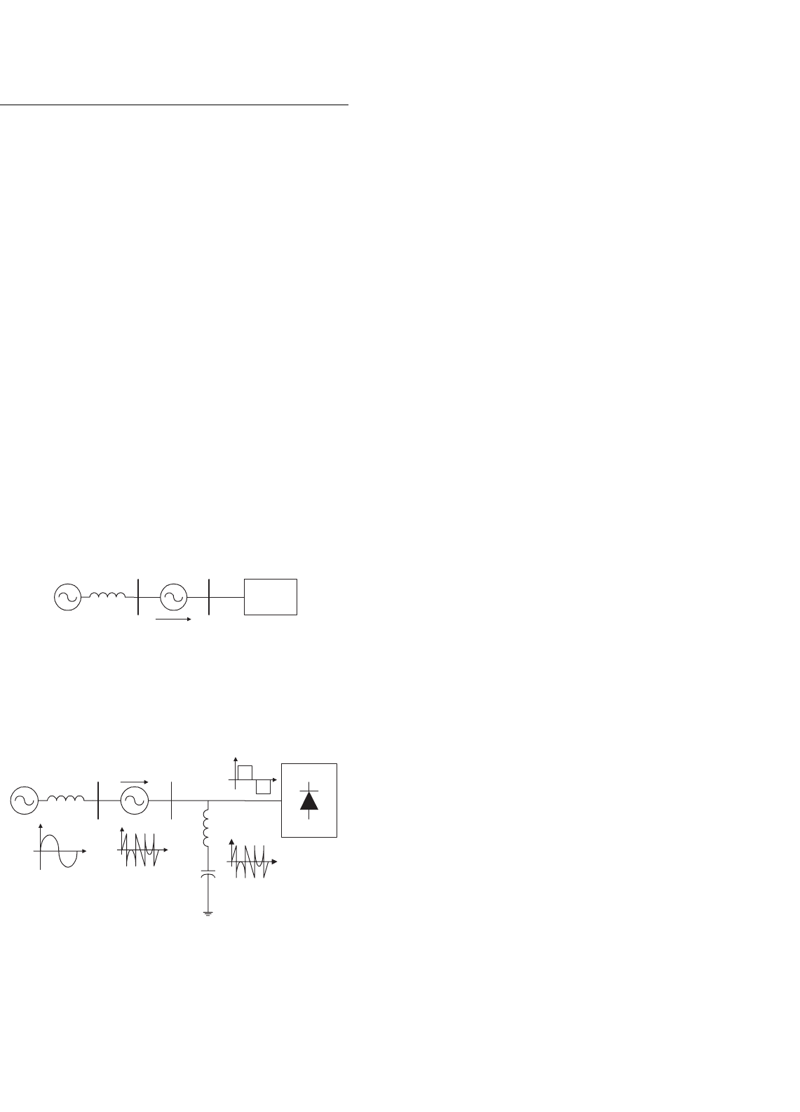
39.4 Series Active Power Filters
Series active power filters were introduced by the end of
the 1980s [5], and operate mainly as a voltage regulator
and harmonic isolator between the non-linear load and the
utility system. The series-connected active power filter is
more preferable to protect the consumer from an inadequate
supply voltage quality. This type of approach is specially rec-
ommended for compensation of voltage unbalances, voltage
distortion, and voltage sags from the ac supply, and for low
power applications represents an economically attractive alter-
native to UPS, since no energy storage (battery) is necessary
and the overall rating of the components is smaller. The series
active power filter injects a voltage component in series with
the supply voltage and therefore can be regarded as a con-
trolled voltage source, compensating voltage sags and swells
on the load side (Fig. 39.29).
If passive LC filters are connected in parallel to the load,
the series active power filter operates as an harmonic isolator
forcing the load current harmonics to circulate mainly through
the passive filter rather than the power distribution system
(hybrid topology) (Fig. 39.30). The main advantage of this
scheme is that the rated power of the series active power filter is
a small fraction of the load kVA rating, typically 5%. However,
Load
V
Load
AC
Supply
V
sys.
Compensation
Voltage
Series
Active Filter
FIGURE 39.29 The series active power filter operating as a voltage
compensator.
V
Load
AC
Supply
V
sys.
+
−
V
ak
I
sys.
V
ak
Passive
Filter
I
Fil.
Non-linear
Load
I
Load
Series Active
Filter
FIGURE 39.30 Combination of series active power filter and passive
filter for current harmonic compensation.
the rated apparent power of the series active power filter may
increase, in case voltage compensation is required.
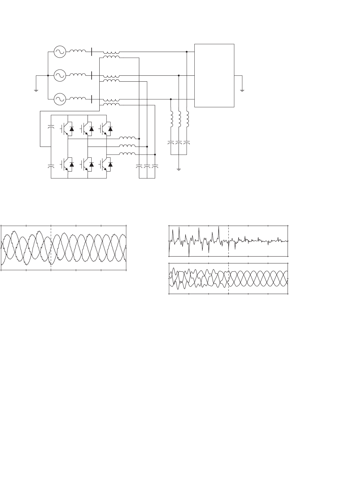
39.4.1 Power Circuit Structure
The topology of the series active power filter is shown in
Fig. 39.31. In most cases, the power circuit configuration is
based on a three-phase PWM voltage-source inverter con-
nected in series with the power lines through three single-phase
coupling transformers. For certain type of applications, the
three-phase PWM voltage-source converter can be replaced
by three single-phase PWM inverters. However, this type of
approach requires more power components, which increases
the cost.
In order to operate as an harmonic isolator, a parallel LC
filter must be connected between the non-linear loads and
the coupling transformers (Fig. 39.30). Current harmonic
and voltage compensation are achieved by generating the
appropriate voltage waveforms with the three-phase PWM
voltage-source inverter, which are reflected in the power sys-
tem through three coupling transformers. With an adequate
control scheme, series active power filters can compensate
for current harmonics generated by non-linear loads, voltage
unbalances, voltage distortion, and voltage sags or swells at
the load terminals. However, it is very difficult to compensate
the load power factor with this type of topology. In four-wire
power distribution systems, series active power filters with the
power topology can also compensate the current harmonic
components that circulate through the neutral conductor.
39.4.2 Principles of Operation
Series active power filters compensate current system dis-
tortion caused by non-linear loads by imposing a high
impedance path to the current harmonics, which forces the
high-frequency currents to flow through the LC passive fil-
ter connected in parallel to the load (Fig. 39.30). The high
impedance imposed by the series active power filter is cre-
ated by generating a voltage of the same frequency that the
current harmonic component needs to be eliminated. Voltage
regulation or voltage unbalance can be corrected by compen-
sating the fundamental frequency positive, negative, and zero
sequence voltage components of the power distribution system
(Fig. 39.29) In this case, the series active power filter injects
a voltage component in series with the supply voltage and
therefore can be regarded as a controlled voltage source, com-
pensating voltage regulation on the load side (sags or swells),
and voltage unbalance. Voltage injection of arbitrary phase
with respect to the load current implies active power trans-
fer capabilities which increases the rating of the series active
power filter, and in most cases requires an energy storage ele-
ment connected in the dc bus. Voltage and current waveforms
1086 L. Morán and J. Dixon
V
an
L
s
C/T
V
cn
L
s
C/T
V
bn
L
s
C/T
Nonlinear
Single Phase
or
Three Phase
Loads
Three-Phase PWM-VSI
(Active Power Filter)
Ripple Filter
Passive
Filter
FIGURE 39.31 The series active power filter topology.
200V
0V
−200V
120ms 140ms 160ms 180ms 200ms
FIGURE 39.32 Load voltage waveforms for voltage unbalance compen-
sation. Phase-to-neutral voltages at the load terminals before and after
series compensation. (Compensation starts at 140 ms, current harmonic
compensator not operating.)
shown in Figs. 39.32, 39.33, and 39.34 illustrate the compen-
sation characteristics of a series active power filter operating
with a shunt passive filter.
39.4.3 Power Circuit Design
The power circuit topology of the series active power filter is
composed by the three-phase PWM voltage-source inverter,
the second-order resonant LC filters, the coupling transform-
ers, and the secondary ripple frequency filter (Fig. 39.30). The
design characteristics for each of the power components are
described below.
80ms 100ms 120ms 140ms 160ms 180ms 200ms
Time
200A
0A
−200A
4.0A
0.0A
−4.0A
(a)
(b)
FIGURE 39.33 System current waveforms for current harmonic com-
pensation: (a) neutral current flowing to the ac mains before and after
compensation and (b) line currents flowing to the ac mains before and
after compensation. (Voltage unbalance compensator not operating.)
39.4.3.1 PWM Voltage-source Inverter
Since series active power filter can compensate voltage unbal-
ance and current harmonics simultaneously, the rated power
of the PWM voltage-source inverter increases compared with
other approaches that compensate only current harmonics,
since voltage injection of arbitrary phase with respect to the
load current implies active power transfer from the inverter
to the system. Also, the transformer leakage inductance entails
fundamental voltage drop and apparent power, which has to
be supported by the inverter, reducing the series active filter
39 Active Filters 1087
60ms 80ms 100ms 120ms 140ms 160ms 180ms 200ms
Time
50
−50
200
−200
50
−50
(a)
(b)
(c)
FIGURE 39.34 Load voltages and system currents for voltage unbalance
and current harmonic compensation, before and after compensation:
(a) power system neutral current; (b) phase-to-neutral load voltages; and
(c) power system line current.
inverter rating available for harmonic and voltage compensa-
tion. The rated apparent power required by the inverter can be
obtained by calculating the apparent power generated in the
primary of the coupling transformers. The voltage reflected
across the primary winding of each coupling transformer is
defined in Eq. (39.43).
V
series
=
K
2
1
k=1
I
2
sk
1/2
+K
2
2
{
V
2
+V
0
}
2
1/2
(39.43)
where V
series
is the rms voltage across the primary wind-
ing of the coupling transformer. Equation (39.43) shows that
the voltage across the primary winding of the transformer is
defined by two terms. The first one is inversely proportional
to the quality factor of the passive LC filter, while the sec-
ond one depends on the voltage unbalance that needs to be
compensated. K
1
depends on the LC filter values while K
2
is equal to one. The current flowing through the primary
winding of the coupling transformer, due to the harmonic
currents (Eq. (39.44)), can be obtained from the equivalent
circuit shown in Fig. 39.35.
I
sk
=
Z
fk
I
lk
Z
fk
+Z
sk
+K
1
(39.44)
where V
series
=−K
1
I
sk
. The fundamental component of the
primary current depends on the amplitude of the negative and
zero sequence component of the source voltage due to the
system unbalance.
Z
sk
I
sk
V
series
I
fk
L
f
C
f
I
Load
k
FIGURE 39.35 The equivalent circuit of the series active power filter
for harmonic components.
39.4.3.2 Coupling Transformer
The purpose of the three coupling transformers is not only to
isolate the PWM inverters from the source but also to match
the voltage and current ratings of the PWM inverters with
those of the power distribution system. The total apparent
power required by each coupling transformer is one-third the
total apparent power of the inverter. The turn ratio of the
current transformer is specified according to the inverter dc
bus voltage, K
1
and V
ref
. The correct value of the turn ratio “a”
must be specified according to the overall series active power
filter performance. The turn ratio of the coupling transformer
must be optimized through the simulation of the overall active
power filter, since it depends on the values of different related
parameters. In general, the transformer turn ratio must be high
in order to reduce the amplitude of the inverter output current
and to reduce the voltage induced across the primary winding.
Also, the selection of the transformer turn ratio influences the
performance of the ripple filter connected at the output of the
PWM inverter. Taking into consideration all these factors, in
general, the transformer turn ratio is selected equal to 1:20.
39.4.3.3 Secondary Ripple Filter
The design of the ripple filter connected in parallel to the
secondary winding of the coupling transformer is performed
following the method presented by Akagi in [6]. However, it
is important to notice that the design of the secondary ripple
filter depends mainly on the coupling transformer turn ratio
and the current modulator used to generate the inverter gat-
ing signals. If the triangular carrier is used, the frequency of
the triangular waveform has to be considered in the design of
the ripple filter. The ripple filter connected at the output of the
inverter avoid the induction of the high-frequency ripple volt-
age generated by the PWM inverter switching pattern at the
terminals of the primary winding of the coupling transformer.
In this way, the voltage applied in series to the power sys-
tem corresponds to the components required to compensate
voltage unbalanced and current harmonics. The single-phase
equivalent circuit is shown in Fig. 39.36.