Power electronic handbook
Подождите немного. Документ загружается.

1088 L. Morán and J. Dixon
L
fr
C
fr
Z
sys
V
inv
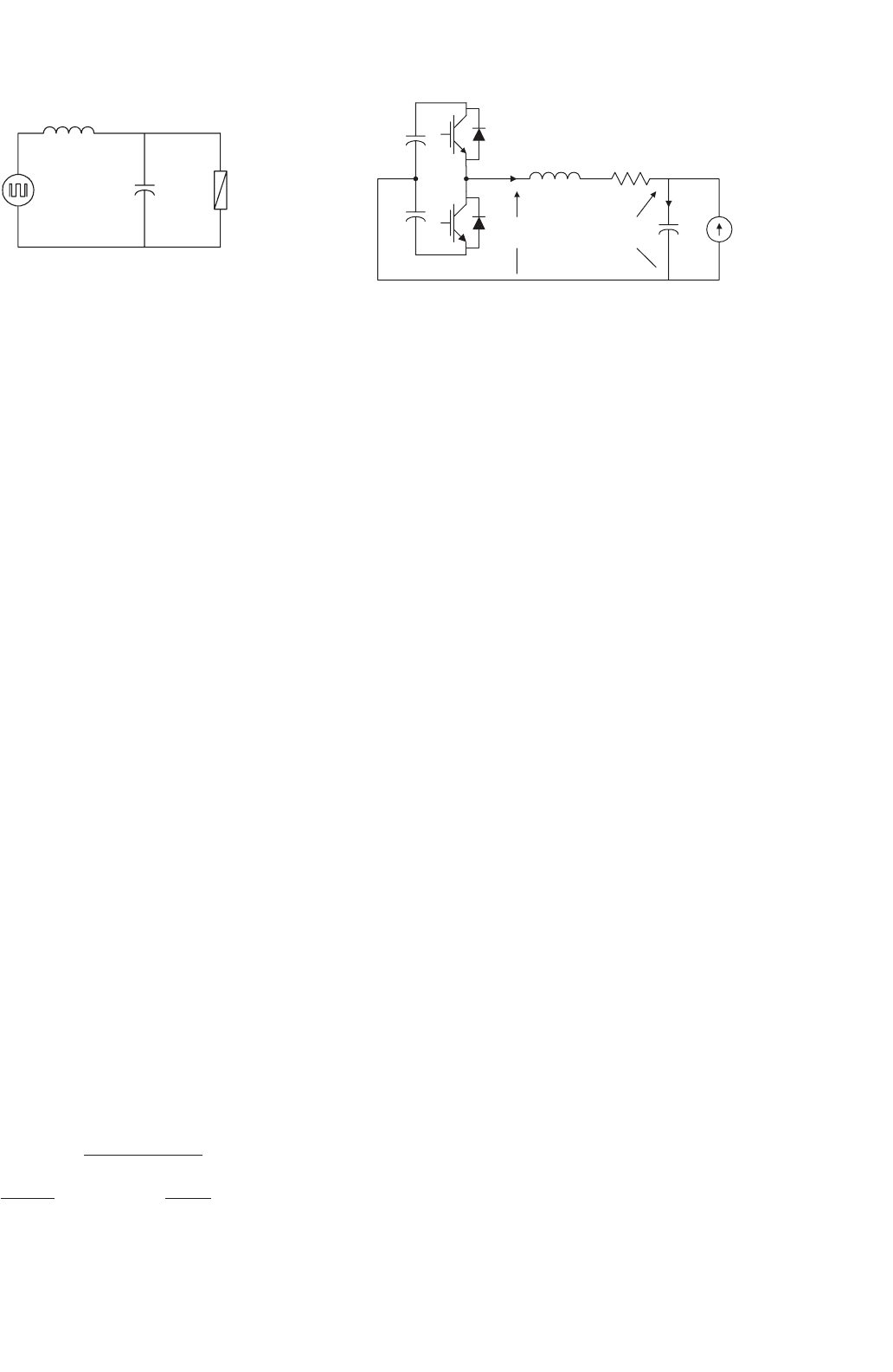
FIGURE 39.36 The single-phase equivalent circuit of the inverter
output ripple filter.
The voltage reflected in the primary winding of the cou-
pling transformer has the same waveform as that of the voltage
across the filter capacitor. For low-frequency components, the
inverter output voltage must be almost equal to the voltage
across C
fr
. However, for high-frequency components, most of
the inverter output voltage must drop across L
fr
, in which case
the voltage at the capacitor terminals is almost zero. Moreover,
C
fr
and L
fr
must be selected in order not to exceed the burden
of the coupling transformer. The ripple filter must be designed
for the carrier frequency of the PWM voltage-source inverter.
To calculate C
fr
and L
fr
the system equivalent impedance at
the carrier frequency, Z
sys
, reflected in the secondary must be
known. This impedance is equal to
Z
sys(secondary)
= a
2
·Z
sys(primary)
(39.45)
For the carrier frequency, the following design criteria must
be satisfied:
(i) X
Cfr
X
Lfr
– to ensure that at the carrier fre-
quency most of the inverter output
voltage will drop across L
fr
.
(ii) X
Cfr
and X
Lfr
Z
sys
– to ensure that the voltage divider
is between L
fr
and C
fr
.
The small-rated LC passive filter exhibits a high quality
factor circuit because of the high impedance on the out-
put side. Oscillation between the small-rated inductor and
capacitor may occur, causing undesirable high-frequency volt-
age across the ripple filter capacitor, which is reflected in
the primary winding of the coupling transformer generating
high-frequency current to flow through the power distribution
system. It is important to note that this oscillation is very dif-
ficult to eliminate through the design and selection of the L
fr
and C
fr
values. However, it can be eliminated with the addition
of a new control loop. The cause of the output voltage oscil-
lation is explained with the help of Fig. 39.37. The transfer
function G
p
(s) between the input voltage V
i
(s) and the output
voltage V
C
(s) is given by the equation:
G
p
(s) =
ω
2
n
s
2
+2ξω
n
s +ω
2
n
(39.46)
where ω
n
=
!
1/L
fr
C
fr
and ξ = r
L
/2
!
C
fr
/L
fr
.
V
i
V
C
L
fr
R
fr
C
fr
I
s
I
Lfr
I
Cfr
FIGURE 39.37 Single-phase equivalent circuit of series active power
filter connected to the ripple filter.
Normally, the damping factor ξ is smaller than one, causing
the voltage oscillation across the capacitor ripple filter, C
fr
.
Generally, relatively low impedance loads are connected to the
output terminals of voltage-source PWM inverters. In these
cases, the quality factor of the LC filter can be low, and the
oscillation between the inductor L
fr
and the capacitor C
fr
is
avoided [7].
39.4.3.4 Passive Filters
Passive filters connected between the non-linear load and the
series active power filter play an important role in the com-
pensation of the load current harmonics. With the connection
of the passive filters the series active power filter operates as an
harmonic isolator. The harmonic isolation feature reduces the
need for precise tuning of the passive filters and allows their
design to be insensitive to the system impedance and elimi-
nates the possibility of filter overloading due to supply voltage
harmonics. The passive filter can be tuned to the dominant
load current harmonic and can be designed to correct the load
displacement power factor.
However, for industrial loads connected to stiff supply, it is
difficult to design passive filters that can absorb a significant
part of the load harmonic current and therefore its effective-
ness deteriorates. Specially, for compensation of diode rectifier
type of loads, where a small kVA passive filter is required,
it is difficult to achieve the required tuning to absorb sig-
nificant percentage of the load harmonic currents. For this
type of application, the passive filter cannot be tuned exactly
to the harmonic frequencies because they can be overloaded
due to the system voltage distortion and/or system current
harmonics.
The single-phase equivalent circuit of a passive LC filter
connected in parallel to a non-linear current source and to the
power distribution system is shown in Fig. 39.38. From this
figure, the design procedure of this filter can be derived. The
harmonic current component flowing through the passive fil-
ter i
fh
and the current component flowing through the source
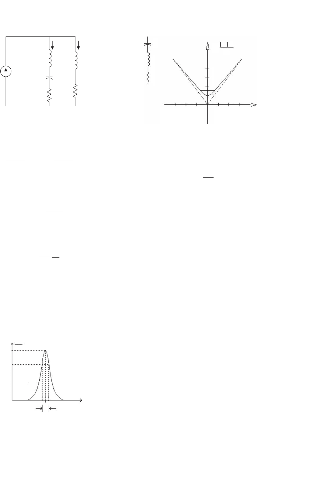
39 Active Filters 1089
I
fh
L
f
C
f
R
f
L
S
R
S
I
Sh
I
h
FIGURE 39.38 The single-phase equivalent circuit of the passive filter
connected to a non-linear load.
i
sh
are given by the following expressions:
i
fh
=
Z
s
Z
s
+Z
f
i
h
; i
sh
=
Z
f
Z
s
+Z
f
i
h
(39.47)
At the resonant frequency the inductive reactance of the
passive filter is equal to the capacitive reactance of the filter,
that is:
2πfrL =
1
2πfrC
(39.48)
Therefore, the resonant frequency of the passive filter is
equal to:
fr =
1
2π
√
LC
(39.49)
The passive filter band width is defined by the upper and
lower cut-off frequency, at which values the filter current gain
is −3 dB, as shown in Fig. 39.39.
The magnitude of the passive filter impedance as a function
of the frequency is shown in Fig. 39.40.
At the resonant frequency the passive filter magnitude is
equal to the resistance. If the resistance is zero, the filter is in
1
I
fh
I
h
0.707
fr
BW
f [Hz]
FIGURE 39.39 The passive filter bandwidth.
C
Y =
4
3
2
1
1
Capacitive Mode
−3 −2 −1123
X= Qδ
Inductive Mode
Zω Q
Z
0
L
R
FIGURE 39.40 The frequency response of the passive LC filter.
short circuit. The quality factor of the passive filter is defined
by the following expression:
Q =
ω
n
L
R
(39.50)
It is important to note that the operation of the series active
power filter with off-tuned passive filter has an adverse impact
on the inverter power rating compared to the normal case.
The more off-tuned the passive filter, the more rated apparent
power is required by the series active power filter.
39.4.3.5 Protection Requirements
Short circuits in the power distribution system generate large
currents that flow through the power lines until the circuit
breaker operates clearing the fault. The total clearing time of a
short circuit depends on the time delay imposed by the protec-
tion system. The clearing time cannot be instantaneous due to
the operating time imposed by the overcurrent relay and by the
total interruption time of the power circuit breaker. Although
power system equipment, such us power transformers, cables,
etc. are designed to withstand short-circuit currents during
at least 30 cycles, the active power filter may suffer severe
damage during this short time. The withstand capability of the
series active power filter depends mainly on the inverter power
semiconductor characteristics.
Since the most important feature of series active power fil-
ters is the small rated power required to compensate the power
system, typically 10–15% of the load rated apparent power,
the inverter semiconductors are rated for low values of block-
ing voltages and continuous currents. This makes series active
power filters more vulnerable to power system faults.
The block diagram of the protection scheme described in
this section is shown in Fig. 39.41. It consists of a varistor con-
nected in parallel to the secondary winding of each coupling
transformer, and a couple of antiparallel thyristors [8]. A spe-
cial circuit detects the current flowing through the varistors
and generates the gating signals of the antiparallel thyristors.
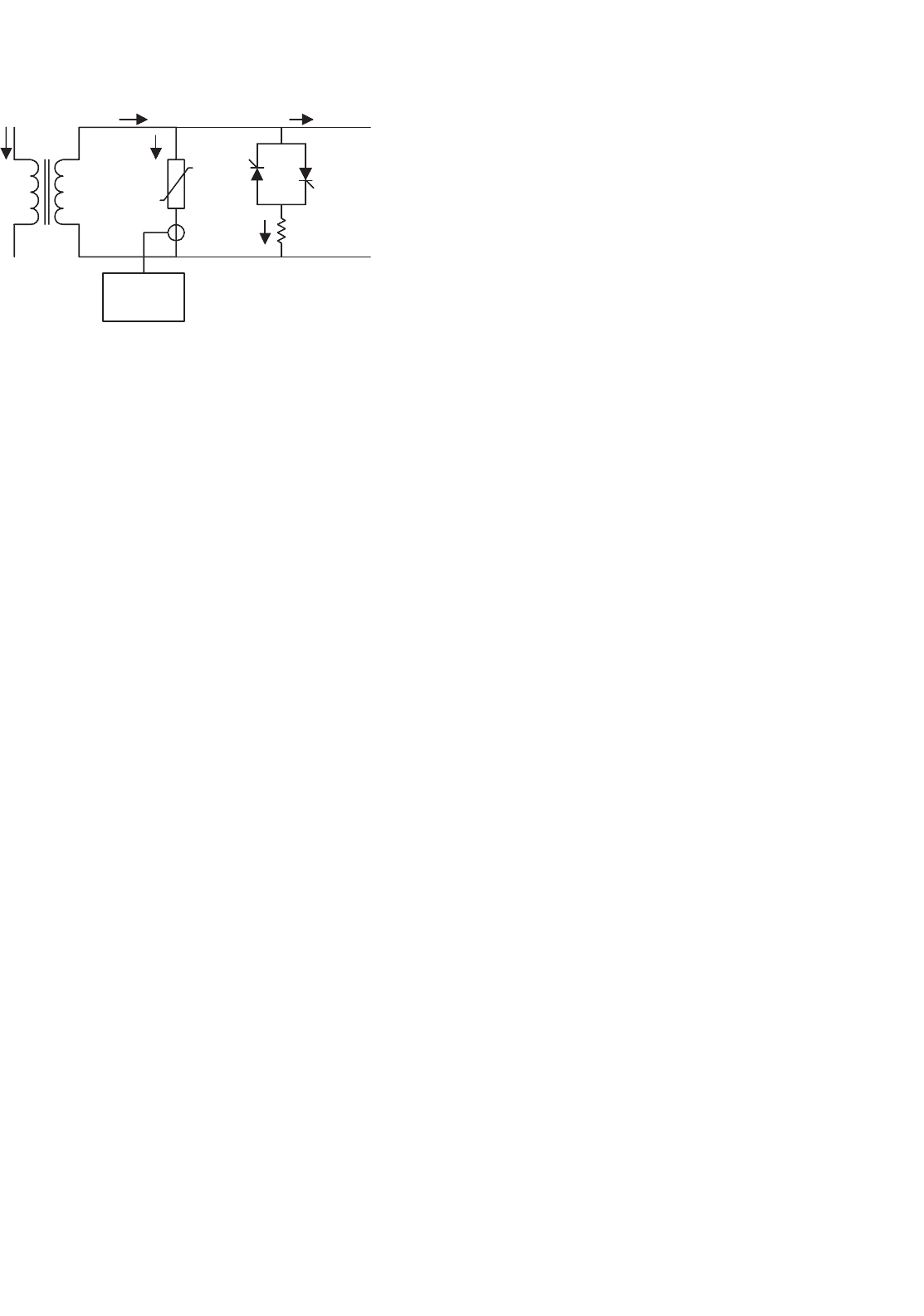
1090 L. Morán and J. Dixon
Control Circuit
Sw's
I
prim
I
sec
I
var
I
inv
I
Rsw
R
sw
sw1 sw2
FIGURE 39.41 The series active power filter protection scheme.
The protection circuit of the series active power filter must
protect only the PWM voltage-source inverter connected to
the secondary of the coupling transformers and must not
interfere with the protection scheme of the power distribution
system. Since the primary of the active power filter coupling
transformers are connected in series to the power distribu-
tion system, they operate as current transformers, so that
their secondary windings cannot operate in open circuit. For
this reason, if a short circuit is detected in the power distri-
bution system, the PWM voltage-source inverter cannot be
disconnected from the secondary of the current transformer.
Therefore, the protection scheme must be able to limit the
amplitude of the currents and voltages generated in the sec-
ondary circuits. This task is performed by the varistors and by
the magnetic saturation characteristic of the transformers.
The main advantages of the series active power filter
protection scheme described in this section are the following:
(i) it is easy to implement and has a reduced cost,
(ii) it offers full protection against power distribution
short-circuit currents, and
(iii) it does not interfere with the power distribution
system.
When short-circuit currents circulate through the power
distribution system, the low saturation characteristic of the
transformers increases the current ratio error and reduces the
amplitude of the secondary currents. The larger secondary
voltages induced by the primary short-circuit currents are
clamped by the varistors, reducing the amplitude of the PWM
voltage-source inverter currents. After a few cycles of dura-
tion of the short circuit, the PWM voltage-source inverter
is bypassed through a couple of antiparallel thyristors, and
at the same time the gating signals applied to the PWM
voltage-source inverter are removed. In this way, the PWM
voltage-source inverter can be turned off. The principles of
operation and the effectiveness of the protection scheme are
shown in Fig. 39.42.
The secondary short-circuit currents will circulate through
the antiparallel thyristors and the varistors until the fault is
cleared by the protection equipment of the power distribution
system.
By using the protection scheme described in this sub-
section, the voltage and currents reflected in the secondary
of the coupling transformers are significantly reduced. When
short-circuit currents circulate through the power distribu-
tion system, the low saturation characteristic of the coupling
transformers increases the current ratio error and reduces the
amplitude of the secondary voltages and currents. Moreover,
the saturated high secondary voltages induced by the primary
short-circuit currents are clamped by the varistors, reducing
the amplitude of the PWM voltage-source inverter ac currents.
Once the secondary current exceeds a predefined reference
value, the PWM voltage-source inverter is bypassed through
a couple of antiparallel thyristors, and then the gating signals
applied to the PWM voltage-source inverter are removed. The
effectiveness of the protection scheme is shown in Fig. 39.43.
By increasing the current ratio error due to the magnetic sat-
uration, the energy dissipated in the secondary of the coupling
transformer is significantly reduced. The total energy dissi-
pated in the varistor for the different protection conditions is
shown in Fig. 39.44.
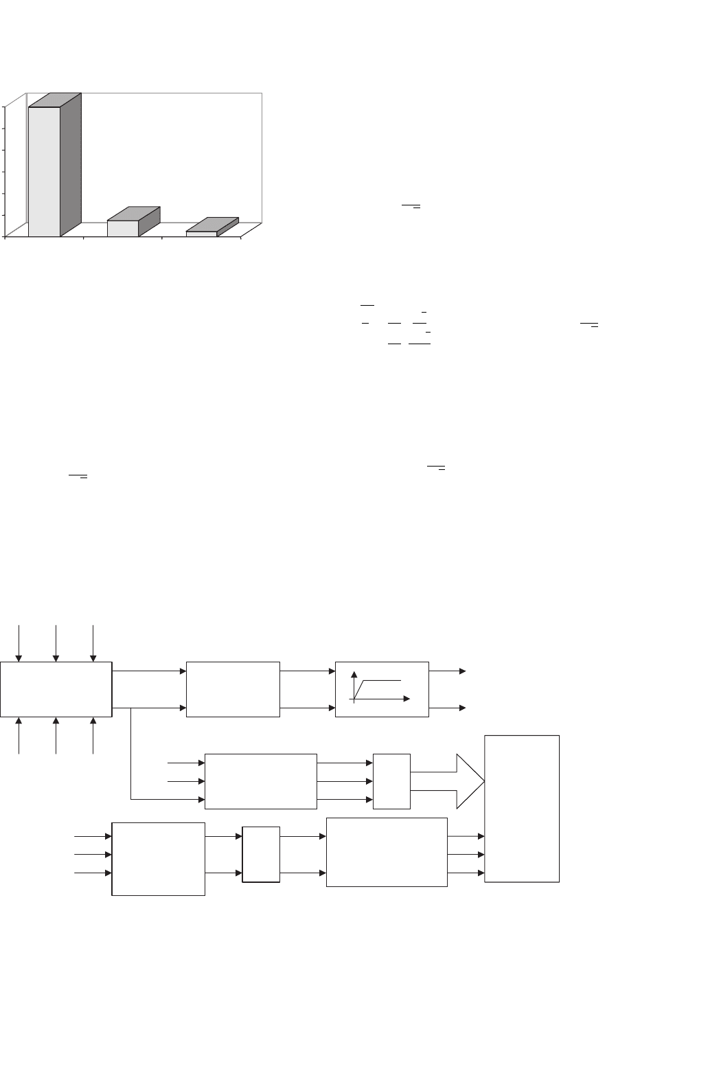
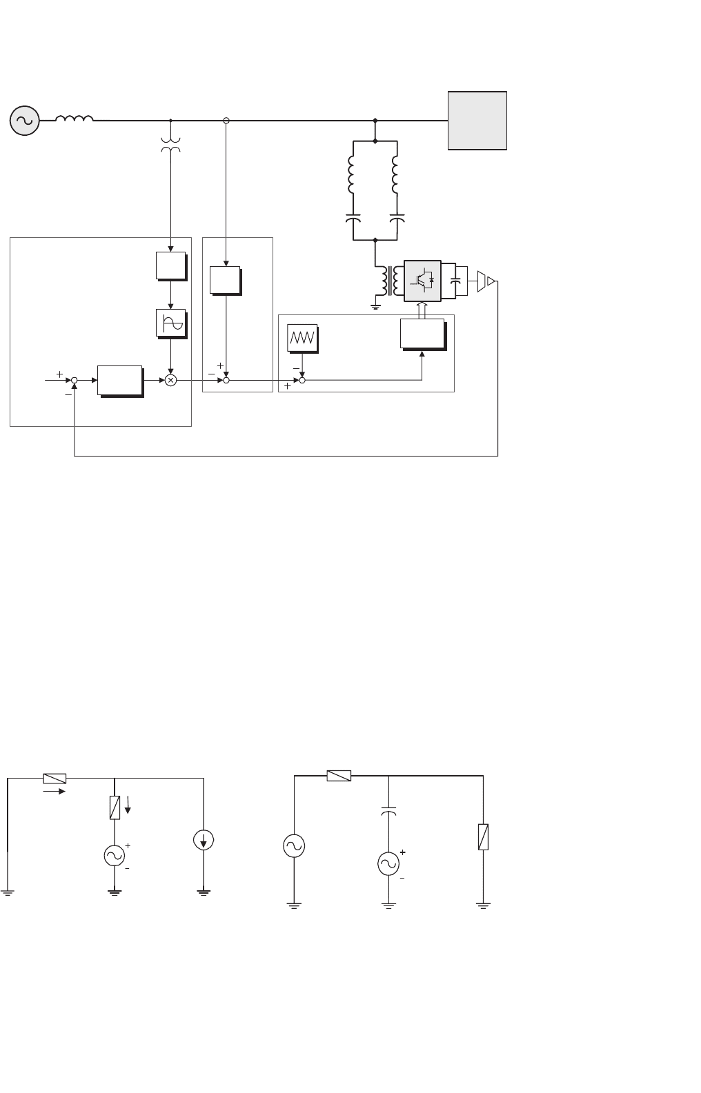
39.4.4 Control Issues
The block diagram of a series active power filter control scheme
that compensates current harmonics and voltage unbalance
simultaneously is shown in Fig. 39.45.
Current and voltage reference waveforms are obtained by
using the Park transformation (instantaneous reactive power
theory) voltage unbalance is compensated by calculating the
negative and zero sequence fundamental components of the
system voltages. These voltage components are added to the
source voltages through the coupling transformers compen-
sating the voltage unbalance at the load terminals. In order
to reduce the amplitude of the current flowing through the
neutral conductor, the zero sequence components of the line
currents are calculated. In this way, it is not necessary to sense
the current flowing through the neutral conductor.
39.4.4.1 Reference Signals Generator
The compensation characteristics of series active power fil-
ters are defined mainly by the algorithm used to generate
the reference signals required by the control system. These
reference signals must allow current and voltage compensa-
tion with minimum time delay. Also it is important that the
accuracy of the information contained in the reference signals
allows the elimination of the current harmonics and voltage
unbalance present in the power system. Since the voltage and
39 Active Filters 1091
0s 20ms 40ms 60ms 80ms 100ms
Time
200V
0V
−200V
2.0KA
0A
−2.0KA
(a)
(b)
0s 20ms 40ms 60ms 80ms 100ms
Time
(c)
(d)
(e)
100A
−100A
80A
−0A
100A
−100A
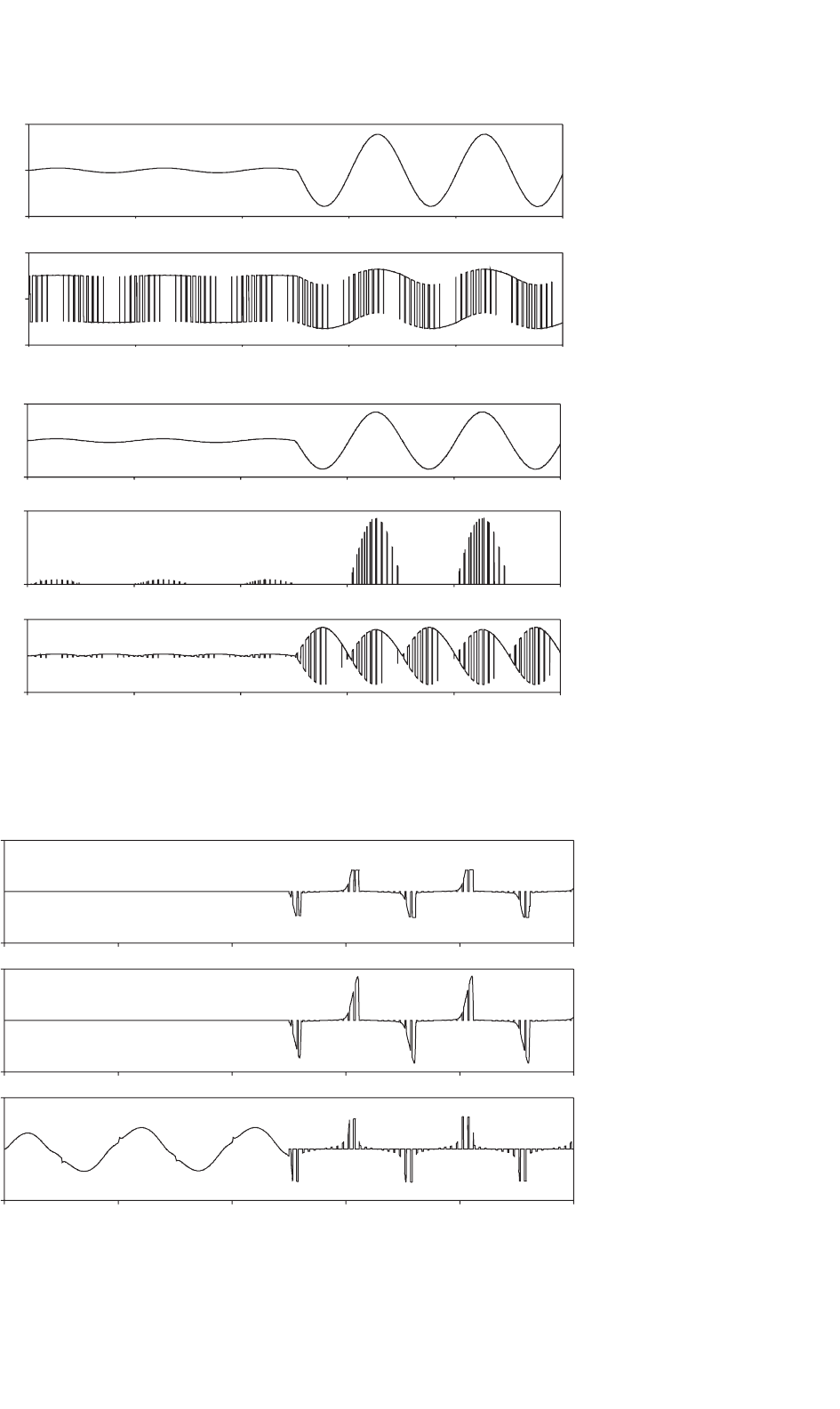
FIGURE 39.42 Current waveforms of the series active power filter during a three-phase short circuit in the power distribution system set at 50 ms:
(a) power distribution system line current; (b) current transformer secondary voltage; (c) inverter ac current; (d) current through an inverter leg; and
(e) inverter dc bus current.
0s 20ms 40ms 60ms 80ms 100m
s
Time
10A
−10A
20A
−20A
10A
−10A
(a)
(b)
(c)
FIGURE 39.43 Current waveforms for a line-to-line short circuit in the power distribution system. The protection scheme is implemented with the
varistor, a couple of antiparallel thyristors, and a coupling transformer with low saturation characteristic: (a) current through the varistor; (b) current
through the thyristors; and (c) inverter ac current.
1092 L. Morán and J. Dixon
ABC
120
15
5
0
20
40
60
80
100
120
Type of Protection
Energy [Joule]
FIGURE 39.44 The total energy dissipated in the varistor during the
power system short circuit for different protection schemes implemen-
tations: (a) only with the varistor used; (b) the varistor is connected
in parallel to a bidirectional switch; and (c) with the complete pro-
tection scheme operating (including the coupling transformer with low
saturation characteristics).
current control scheme are independent, the equations used
to calculate the voltage reference signals are the following:
v
a0
v
a1
v
a2
=
1
√
3
11 1
1 aa
2
1 a
2
a
.
v
a
v
b
v
c
(39.51)
The voltages v
a
, v
b
, and v
c
correspond to the power sys-
tem phase-to-neutral voltages before the current transformer.
The reference voltage signals are obtained by making the pos-
itive sequence component, v
a1
zero and then applying the
Park
Transformation
Calculation of
p and q
V
a
, V
b
, V
o
V
a
, V
b
, V
0
I
a
, I
b
, I
0
p(t)
q(t)
p
ref
q
ref
High Pass Filter
I
a
I
b
I
c
V
an
V
an
V
bn
V
cn
V
bn
V
cn
Inverse
Park
Transformation
p
ref
q
ref
K
I
aref
I
bref
I
cref
Gating
Signals
Generator
Inverse
Sequence
Components
Transformation
− V(−)
− V(0)
− 1
Fundamental
Voltage
Sequence
Components
V(−)
V(0)
Voltage Reference Generator for Unbalance
Compensation
Voltage Reference Generator for Current
Harmonics Compensation
FIGURE 39.45 Compensation scheme for voltage unbalance correction.
inverse of the Fortescue transformation. In this way the series
active power filter compensates only voltage unbalance and not
voltage regulation. The reference signals for the voltage unbal-
ance control scheme are obtained by applying the following
equations:
v
refa
v
refb
v
refc
=
1
√
3
11 1
1 a
2
a
1 aa
2
.
−v
ao
0
−v
a2
(39.52)
In order to compensate current harmonics generated by the
non-linear loads, the following equations are used:
i
aref
i
bref
i
cref
=
2
3
·
10
−1
2
√
3
2
−1
2
−
√
3
2
·
v
α
v
β
−v
β
v
α
−1
p
ref
q
ref
+
1
√
3
i
0
i
0
i
0
(39.53)
where i
0
is the fundamental zero sequence component of the
line current and is calculated using the Fortescue transforma-
tion Eq. (39.50).
i
0
=
1
√
3
(
i
a
+i
b
+i
c
)
(39.54)
In Eq. (39.40) p
ref
, q
ref
, v
α
, and v
β
are defined accord-
ing to the instantaneous reactive power theory. In order to
avoid the compensation of the zero sequence fundamental
frequency current the reference signal i
0
must be forced to cir-
culate through a high-pass filter generating a current i
0
which
39 Active Filters 1093
is used to create the reference signal required to compensate
current harmonics. Finally, the general equation that defines
the references of the PWM voltage-source inverter required to
compensate voltage unbalance and current harmonics is the
following:
V
refa
V
refb
V
refc
= K
1
2
3
10
−1
2
√
3
2
−1
2
−
√
3
2
.
v
α
v
β
−v
β
v
α
−1
p
ref
q
ref
+
1
√
3
i
0
i
0
i
0
+K
2
1
√
3
11 1
1 a
2
a
1 aa
2
.
−v
a0
0
−v
a2
(39.55)
where K
1
is the gain of the coupling transformer which defines
the magnitude of the impedance for high-frequency current
components, and K
2
defines the degree of compensation for
voltage unbalance, ideally K
2
equals 1.
39.4.4.2 Gating Signals Generator
This circuit provides the gating signals of the three-phase
PWM voltage-source inverter required to compensate voltage
unbalance and current harmonic components. The current
and voltage reference signals are added and then the ampli-
tude of the resultant reference waveform is adjusted in order
to increase the voltage utilization factor of the PWM inverter
for steady-state operating conditions. The gating signals of the
inverter are generated by comparing the resultant reference
signal with a fixed frequency triangular waveform. The trian-
gular waveform helps to keep the inverter switching frequency
constant (Fig. 39.46).
A higher voltage utilization of the inverter is obtained if the
amplitude of the resultant reference signal is adjusted for the
steady-state operating condition of the series active power fil-
ter. In this case, the reference current and reference voltage
waveforms are smaller. If the amplitude is adjusted for tran-
sient operating conditions, the required reference signals will
+
+
=
Voltage Reference
Current Reference
+
−
Inverte
r
Gating
Signals
Amplitude
Adjustment
Triangular
Waveform
(4 kHz)
FIGURE 39.46 The block diagram of the gating signals generator.
have a larger value, creating a higher dc voltage in the inverter
and defining a lower voltage utilization factor for steady-state
operating conditions.
The inverter switching frequency must be higher in order
not to interfere with the current harmonics that need to be
compensated.
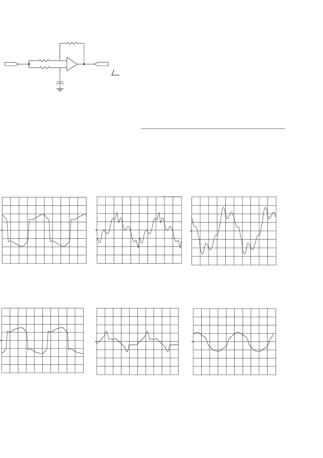
39.4.5 Control Circuit Implementation
Since the control scheme of the series active power filter must
translate the current harmonics components that need to be
compensated in voltage signals, a proportional controller is
used. The use of a PI controller is not recommended since
it would modify the reference waveform and generate new
current harmonic components. The gain for proportional
controller depends on the load characteristics and its value
fluctuates between one and two.
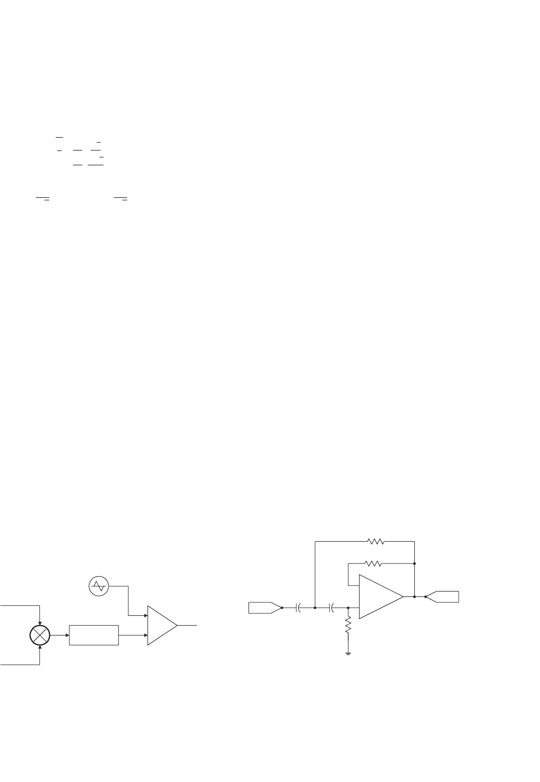
Another important element used in the control scheme is
the filter that allows to generate p
ref
and q
ref
(Fig. 39.35). The
frequency response of this filter is very important and must not
introduce any phase-shift or attenuation to the low-frequency
harmonic components that must be compensated. A high-
pass first-order filter tuned at 15 Hz is adequated. This corner
frequency is required when single-phase non-linear loads are
compensated. In this case, the dominant current harmonic is
the third. An example of the filter that can be used is shown
in Fig. 39.47.
The operator “a” required to calculate the sequence com-
ponents of the system voltages (Fortescue transformation) can
be obtained with the all-pass filter shown in Fig. 39.48.
The phase-shift between V
o
and V
i
is given by the following
expression:
θ = 2 arctan (2πfR
2
C) (39.56)
Since the phase-shift is negative, the operator “a” is obtained
by using an inverter (180
◦
) and then by tuning θ =−60
◦
.
R
2
R
f
C
1
C
2
R
1
+
−
i
i
ref
FIGURE 39.47 The first-order high-pass filter implemented for the
calculation of p
ref
and q
ref
(C
1
= C
2
= 0.1 µF, R
1
= R
f
= 150 k,
R
2
= 50 k).
1094 L. Morán and J. Dixon
v
i
R
C
v
o
= v
i
−θ
R
2
R
1
+
−
FIGURE 39.48 The all-pass filter used as a phase shifter.
The operator “a
2
” is obtained by phase-shifting V
i
by
−120
◦
. V
i
is synchronized with the system phase-to-neutral
voltage V
an
.
39.4.6 Experimental Results
The viability and effectiveness of series active power filters used
to compensate current harmonics was proved in an exper-
imental setup of 5 kVA. Current waveforms generated by a
(a) (b) (c)
4
4
4
Ch4
20.0mV
M4.00ms
6 Aug 1997
18:59:16
Ch4
20.0mV
M4.00ms
6 Aug 1997
18:59:49
Ch4
20.0mV
M4.00ms
6 Aug 1997
19:00:20
FIGURE 39.49 Experimental results without the operation of the series active power filter: (a) load current; (b) current flowing through the passive
filter; and (c) current through the power supply.
(a) (b) (c)
4
4
4
Ch4
20.0mV
M4.00ms
6 Aug 1997
19:07:02
Ch4
50.0mV
M4.00ms
5 Aug 1997
17:28:30
Ch4
50.0mV
M4.00ms
5 Aug 1997
17:26:24
FIGURE 39.50 Experimental results with the operation of the series active power filter: (a) load current; (b) current flowing through the passive
filter; and (c) current through the power supply.
non-linear load and using only passive filters and the combi-
nation of passive and the series active power filter are shown
in Figs. 39.49 and 39.50.
These figures show the effectiveness of the series active
power filter, which reduces the overall THD of the current
that flows through the power system from 28.9% (with the
operation of only the passive filters) to 9% with the operation
of the passive filters with the active power filter connected in
series. The compensation of the current that flows through the
neutral conductor is shown in Fig. 39.51.
39.5 Hybrid Active Power Filters
Hybrid topologies composed of passive LC filters connected
in series to an active power filter have already been proposed
by the end of the eighties [2, 5, 6, 9, 10, 11]. Hybrid topology
improves significantly the compensation characteristics of sim-
ple passive filters, making the use of active power filter available
for high power applications, at a relatively lower cost. More-
over, compensation characteristics of already installed passive
39 Active Filters 1095
(a) (b)
4
Ch4
50.0mV
M10.0ms
7 Aug 1997
16:31:22
Ch4
50.0mV
M10.0ms
5 Aug 1997
17:25:35
4
FIGURE 39.51 Experimental results of neutral current compensation: (a) current flowing through the neutral without the operation of the series
active power filter and (b) current flowing through the neutral with the operation of the active power filter.
Non-linear
Load
Passive
Filters
System
L
S
V
S
Control Circuit
5
a
7
a
C/T
L
r
C
r
FIGURE 39.52 The hybrid active power filter configuration.
filters can be significantly improved by connecting a series
active power filter at its terminals, giving more flexibility to
the compensation scheme. Most of the technical disadvantages
of passive filters described before can be effectively attenuate
if an active power filter is connected in series to the passive
approach as shown in Fig. 39.52.
The hybrid active power filter topology is shown in
Fig. 39.52. The active power filter is implemented with a
three-phase PWM voltage-source inverter operating at fixed
switching frequency, and connected in series to the passive fil-
ter through a coupling transformer. Basically, the active power
filter forces the utility line currents to become sinusoidal and in
phase with the respective phase-to-neutral voltage, improving
the compensation characteristics of the passive filter.
39.5.1 Principles of Operation
Since the active power filter is connected in series to the
passive filter through a coupling transformer, it imposes a volt-
age signal at its primary terminals that forces the circulation
of current harmonics through the passive filter, improving
its compensation characteristics, independently of the varia-
tions in the selected resonant frequency of the passive filter.
The block diagram of the proposed control scheme shown in
Fig. 39.53 consists of three modules: the dc voltage control,
the voltage reference generator, and the inverter gating signal
generator.
The voltage reference waveform required by the inverter
control scheme is obtained by adjusting the amplitude of a
1096 L. Morán and J. Dixon
L
S
V
S
L
5
C
5
K
1
−1
L
7
C
7
Base Drive
Circuit
Synchro.
Reference Voltage
Generator
Gating Signals
Generator
DC Voltage Control
V
DC
reference
V
m
Triangular
Reference
VSI
PWM
Passive
Filter
Non-linear
Load
Source
Sinusoidal
Waveform
Generator
Voltage
Controller
I
S
I
S
K
Synchronization
Circuit
FIGURE 39.53 The hybrid active power filter topology and associated control scheme.
sinusoidal reference waveform in phase with the respective
phase-to-neutral voltage and then subtracting the respective ac
line current (Fig. 39.53). The sinusoidal reference signal can be
obtained from the voltage system (in case of low voltage dis-
tortion) or it can be generated from an EPROM synchronized
with the respective phase-to-neutral voltage. The amplitude of
this reference waveform controls the inverter dc voltage and
the ac mains displacement power factor. The inverter dc volt-
age varies according with the amount of real power absorbed
by the inverter, while the ac mains power factor depends on
the amount of reactive power generated by the hybrid filter,
which can be controlled by changing the amplitude of the
fundamental component of the inverter output voltage.
V
ch
= K I
Sh
Z
F
Z
S
I
L
V
T
I
Sh
I
Fh
Load
V
c
= β V
T
V
S
C
Z
S
V
T
Passive
filter
at 50Hz
(a) (b)
FIGURE 39.54 Single-phase equivalent circuits of the hybrid active power filter scheme: (a) for current harmonic compensation and (b) for
displacement power factor compensation.
The principles of operation for current harmonic and power
factor compensation are explained with the help of the single-
phase equivalent circuit shown in Fig. 39.54. In the current
harmonic compensation mode, the active filter improves the
filtering characteristic of the passive filter by imposing a voltage
harmonic waveform at its terminals with an amplitude value
equals to:
V
Ch
= K · I
Sh
(39.57)
where I
Sh
is the harmonic content of the line current to
be compensated, and K is the active power filter gain. If
the ac mains voltage is purely sinusoidal, the ratio between
39 Active Filters 1097
the harmonic component of the non-linear load current and
the harmonic component of the ac line current (attenuation
factor) is obtained from Fig. 39.54a and is equal to:
I
Sh
I
Lh
=
Z
F
K + Z
F
+Z
S
(39.58)
Equation (39.58) shows that the filtering characteristics of
the hybrid topology (I
Sh
/I
Lh
) depends on the value of the pas-
sive filter equivalent impedance, Z
F
. Moreover, since the tuned
factor, δ, and the quality factor, Q, can modify the filter band
width and the passive filter harmonic equivalent impedance
(Fig. 39.55), their values must be carefully selected in order to
maintain the compensation effectiveness of the hybrid topol-
ogy. In particular, a high value of the quality factor, Q, defines
a large band width of the passive filter, improving the com-
pensation characteristics of the hybrid topology. On the other
hand, a low value in the quality factor and/or a large value in
the tuned factor increases the required voltage generated by
the active power filter necessary to keep the same compensa-
tion effectiveness, which increases the active power filter rated
power.
Figure. 39.55 shows how the active power filter gain, K,in
Eq. (39.57) affects the harmonic attenuation factor of the line
currents. The attenuation factor of the line current harmonics
expressed in percentage is obtained from Eq. (2), and is shown
in Fig. 39.55, for a power distribution system with two passive
filters tuned at fifth and seventh harmonics.
Also, the K factor affects the THD of the line current, as it
is shown in Eq. (39.59).
THD i =
h=2
[
I
Lh
·(Z
F
/(Z
S
+Z
F
+K ))
]
2
I
S1
(39.59)
Equation (39.59) indicates that the total harmonic distor-
tion of the line current decreases if K increases. In other
words, a better hybrid filter compensation is obtained for
f/50
K=0
K=5
K=15
0
20
40
60
80
Attenuation factor
100
4
2
6 8 10 12 14 16 18
FIGURE 39.55 The attenuation factor of the line current harmonics for
different frequency values.
0 5 10 15 20
0
2
4
6
8
10
12
14
16
K
%
THD
FIGURE 39.56 System line current THD vs K factor.
larger values of voltage harmonic components generated by
the active power filter. Also, it is shown that the compensation
capability of the hybrid filter depends on the compensation
characteristic of the passive filter, that is the filter impedance
value and tuned frequency will affect the active filter rated
power required to satisfy the system line current compensa-
tion requirements. Figure 39.56 shows how the line current
THD is affected for different values of K, for a power distribu-
tion system connected to a high power six-pulses rectifier and
passive filters tuned at the fifth and seventh harmonics.
Displacement power factor correction can be achieved by
controlling the voltage drop across the passive filter capaci-
tor. In order to do that a voltage at fundamental frequency
is generated at the inverter ac terminals, with an amplitude
equals to:
V
C
= β · V
T
(39.60)
Displacement power factor control can be achieve since at
fundamental frequency the passive filter equivalent impedance
is capacitive. The reactive power generated by the passive filter
is obtained by changing the voltage imposed by the active
power filter across the passive filter capacitor terminals. The
passive filter fundamental current component is defined by the
following expression:
i
F
= C
d
dt
(
v
T
−βv
T
)
=
(
1 −β
)
C
dv
T
dt
= C
γ
β
dv
T
dt
(39.61)
Equation (39.61) proves that the equivalent capacitance at
fundamental frequency Cγ , can be modified by changing β.
The reactive power generated by the active filter is β times
the reactive power generated by the passive filter and can be
defined by:
Q
γ
= V
C
·I
F
= βV
T
I
F
(39.62)