Parinov I.A. Microstructure and Properties of High-Temperature Superconductors
Подождите немного. Документ загружается.


8.6 Toughening of Bi-2223 Bulk, Fabricated by Hot-Pressing Method 401
boundary energy and its mobility on grain misorientation, using a correspond-
ing texture component for each grain. For simplicity, we limit the texture
components to two (A and B), which are quite sufficient to describe consider-
able number of test data. In particular, we could model the growth processes
for considered anisotropic Bi-2223 superconductor along the c-direction and
in the ab-plane. Mass transfer between crystallites is based on the following
assumptions [245]:
(1) The migration rate of a boundary between two grains i and j is given by
ν
ij
= m
ij
p
ij
=2γ
ij
(1/R
i
− 1/R
j
) , (8.116)
where p
ij
is the driving force, m
ij
and γ
ij
are the mobility and boundary
energy, (1/R
i
− 1/R
j
) is the average curvature for this grain boundary
and M
ij
=2m
ij
γ
ij
is the grain growth diffusivity.
(2) All grains of the same size and orientation experience the same growth
rate (homogeneity condition).
(3) The grains, surrounding a given grain, are distributed randomly with re-
spect to size and orientation.
Then, the grain growth rate of the size class i with a texture component
A (or B) without the growth stagnation is found by [245]
dR
A(B)
i
/dt = M
A(B)
∗
[1/R
A(B)
∗
− 1/R
A(B)
i
] , (8.117)
where M
A(B)
∗
and R
A(B)
∗
are the integrated diffusivity and integrated critical
radius, respectively, controlling the grain growth of the component A (or B).
Note that the value of R
A(B)
∗
is the intermediate grain size of the component
A (or B) between increasing and decreasing grains, and M
A(B)
∗
determines the
rate of these processes [245]:
M
A
∗
=
F
A
0
R
2
A
1
M
AA
+ F
B
0
R
2
B
1
M
AB
F
A
0
R
2
A
1
+ F
B
0
R
2
B
1
; M
B
∗
=
F
A
0
R
2
A
1
M
BA
+ F
B
0
R
2
B
1
M
BB
F
A
0
R
2
A
1
+ F
B
0
R
2
B
1
;
(8.118)
R
A
∗
=
F
A
0
R
2
A
1
M
AA
+ F
B
0
R
2
B
1
M
AB
F
A
M
AA
R
A
+ F
B
M
AB
R
B
; R
B
∗
=
F
A
0
R
2
A
1
M
BA
+ F
B
0
R
2
B
1
M
BB
F
A
M
BA
R
A
+ F
B
M
BB
R
B
(8.119)
where M
HK
(H, K = A or B) is the grain-growth diffusivity of a boundary
between grains of the orientation classes H and K. The grain fraction of the
size class i with the orientation A (or B) is defined as
F
A(B)
i
= n
A(B)
i
/N
G
;
N
S
#
i=1
(n
A
i
+ n
B
i
)=N
G
;
N
S
#
i=1
(F
A
i
+ F
B
i
)=1; F
A(B)
=
N
S
#
i=1
F
A(B)
i
,
(8.120)
where N
S
and N
G
are the total number of size classes and grains, respectively;
n
A(B)
i
is the number of grains per unit volume of the size class i withorientation
402 8 Computer Simulation of HTSC Microstructure and Toughening
A(orB);R and
0
R
A(B)
1
are the mean radius of grains in the whole system
and that with the orientation component A (or B), respectively:
R =
N
S
#
i=1
F
i
R
i
;
0
R
A(B)
1
=
N
S
#
i=1
F
A(B)
i
R
A(B)
i
/F
A(B)
; (8.121)
0
R
2
1
= R
2
+ σ
2
;
2
R
2
A(B)
3
=
)0
R
A(B)
1*
2
+
σ
A(B)
2
, (8.122)
where σ and σ
A(B)
denote the standard deviations. The size class for a given
grain is found by the cell number, contained in this grain. The condition for
abnormal grain growth in the grain size class i with the orientation A (or B)
in the space (R, t), taking into account (8.117), is found as [245]
!
!
!
1/R
A(B)
∗
− 1/R
A(B)
i
!
!
!
>I
R
/2 , (8.123)
where I
R
=6f
ν
/(πr) is the value of the grain-growth stagnation, f
ν
and r are
the volume fraction and mean radius of the secondary phase particles. It is
assumed that the stagnation parameter is independent of the grain orientation
and is calculated as described above. This parameter, as well as the critical
radii of the components A and B, governs the abnormal grain growth. This
circumstance enables us to define the HTSC ceramic properties and their
dependencies on the secondary phase characteristics.
The size parameters, which are necessary for calculations, are found in
the simulation of the primary re-crystallization. The orientations A and B are
distributed between grains, using the Monte-Carlo procedure, and they do not
change during growth. Moreover, it is assumed that mass transfer between
the grains of different orientations is absent. As an example, we consider the
case of the next diffusion parameters for the orientation classes [2]: M
AB
=
M
BA
=2M
AA
=2M
BB
. This sufficiently arbitrary selection is explained by
the absence of reliable test data for the Bi-2223 ceramic. The mass transport
between grains is simulated in accordance with the grain growth mechanism
at the non-singular surfaces [1034].
The computational algorithm for abnormal grain growth consists of the
following steps:
(1) The distribution of the orientations H (where H = A or B) between the
grains that are formed after primary re-crystallization.
(2) The definition of all neighbors for every grain of both orientation classes.
(3) The determination of adjacent grain couple in each orientation class
(i
H
,j
H
)with max
1≤i
H
,j
H
≤N
S
!
!
1/R
H
i
− 1/R
H
j
!
!
.
(4) The growth of the larger grains from the (i
H
,j
H
)attheexpenseofsmaller
ones.
(5) The checking of the conditions:
!
!
!
1/R
A(B)
∗
− 1/R
A(B)
i
!
!
!
≤ I
R
/2, where
i
H
=1,...,N
S
.

8.6 Toughening of Bi-2223 Bulk, Fabricated by Hot-Pressing Method 403
(6) End of the grain growth in the corresponding component H, if the condi-
tions (5) have been satisfied; else a change of the corresponding parameters
in (8.118)–(8.122) and fulfillment of the steps: (2)–(6) again.
The simulation of intergranular cracking due to cooling is carried out
as before, using (8.4) and (8.5) and the procedure described in detail in
Sect. 8.1.2.
8.6.2 Bi-2223 Toughening by Silver Dispersion
As has been noted above, an addition of Ag ductile phase dispersion to the
Bi-2223 ceramic causes a considerable increasing in the fracture resistance
of the superconductor compared to that of untoughened matrix. It is known
that the main mechanism responsible for enhanced toughness of brittle com-
posites with ductile particles appears to be the crack bridging by the ductile
phase. Here, we limit ourselves to the most important case for HTSC, when
an increasing of the ceramic toughness is independent of the particle size and
ductile strength. This corresponds to the state, when the ductile flow has
occurred in a considerable zone near the crack tip. Then, the toughness in-
creasing due to the ductile particles (stationary crack case) can be estimated
as [988]
1 − ν
2
ef
K
c
K
0
c
=
√
3
1+
10(1 − ν
2
ef
)f
p
(7 − 5ν
ef
)(1 − f
p
)
1/2
, (8.124)
where K
c
and K
0
c
are the fracture toughness with and without toughening,
respectively; f
p
is the ductile particulate concentration, defined by the fraction
of this phase, intercepting the macrocrack path; ν
ef
is effective Poisson’s ratio,
defined by the relative concentration of the Bi-2223 and Ag phases, and also
by the intergranular microcracks, formed during the composite processing.
Under conditions of the modified cubic model, we obtain [428]:
ν
ef
=(1− f
2/3
m
)ν
c
+ f
2/3
m
[ν
m
f
1/3
m
/E
m
+ ν
c
(1 − f
1/3
m
)/E
c
]
[f
1/3
m
/E
m
+(1− f
1/3
m
)/E
c
]
, (8.125)
where the indexes m and c correspond to the metal inclusions and the ceramic
matrix. For the cracked matrix with a microcrack density, β
cr
, Poisson’s ratio,
ν
c
, and Young’s modulus, E
c
, are expressed as [892]
ν
c
ν
0
=
1+[(16/45)(1 − ν
2
0
)/(2 − ν
0
)]β
cr
1+[(16/45)(1 − ν
2
0
)(10 − 3ν
0
)/(2 − ν
0
)]β
cr
; (8.126)
E
c
E
0
=1/
1+
16(1 − ν
2
0
)(10 − 3ν
0
)
45(2 − ν
0
)
β
cr
, (8.127)
where ν
0
and E
0
are the intrinsic elastic modules.
Since the metallic inclusions have a greater thermal expansion than the
ceramic matrix [564], the residual tension (σ
R
) occurs in the metal, but the ce-
ramic is compressed. This internal stress state affects the toughening, because
the compressive stresses in matrix must be exceeded within the bridging zone

404 8 Computer Simulation of HTSC Microstructure and Toughening
before beginning of crack opening. The additive increment of the toughness
is estimated as [988]
ΔG
R
≈ αf
p
σ
R
u
∗
, (8.128)
where α(∼ 0.25) is a factor that depends on the precise nature of the func-
tion σ = σ(u); u
∗
is the total crack opening when the ductile material fails
(Fig. 8.35a). For cylindrical metal particles in a non-hardening material, the
axial residual stress, σ
z
R
, can be obtained as [444, 988]
σ
z
R
E
m
ΔαΔT
∗
=
3
3(1 − 2ν
m
)+2(1+ν
c
)(E
m
/E
c
)
, (8.129)
where Δα is the thermal expansion factor difference of the phases; ΔT
∗
is the
cooling thermal range, in which the rapid creep provides relaxation.
L
u*
h
σ
e
= σ
0
4
(a)
(b)
1
2
3
6
5
4
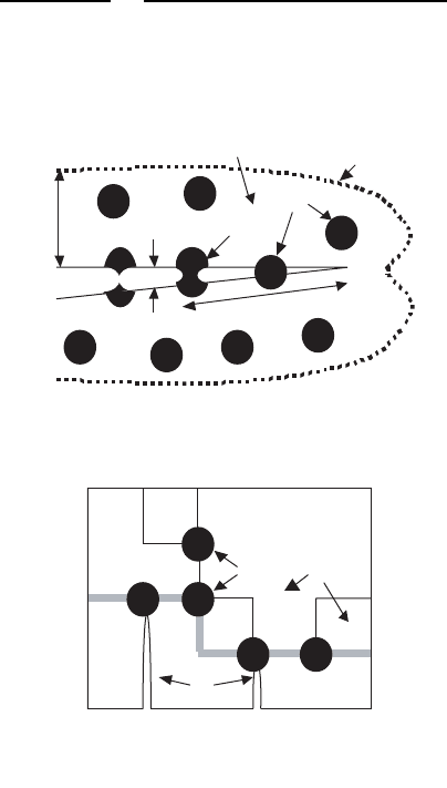
Fig. 8.36. (a) Scheme of crack (1) bridging by intercepted ductile silver particles (4);
the process (2) and stretch (3) zones of plastically distorted particles are shown (h
and L are the corresponding zone sizes; u
∗
is the residual crack opening at link failure
and σ
0
is the yield strength) [988]; (b) a model fragment of Bi-2223/Ag composite
with the Bi-2223 grains (5) and cooling microcracks (6); macrocrack is denoted by
gray line

8.6 Toughening of Bi-2223 Bulk, Fabricated by Hot-Pressing Method 405
Table 8.9. Numerical results [577]
D/δ β
cr
l
cr
/b f
p
K
c
/K
0
c
2.40 0.15 1.51 0.12 1.96
2.84 0.22 1.62 0.10 1.92
It has been suggested in computer simulations that the silver inclusions
are localized at the triple junctions, where there are usually microdefect sites,
healed by the Ag. The necessary parameters for Ag particles are given else-
where [845]. The optimum Ag volume concentration in the Bi-2223 bulk is
assumed to be f
m
=0.2 [564]. Finally, we modeled the intergranular macro-
crack path (see Fig. 8.36b), using Viterbi’s algorithm for graphs [796, 823],
taking into account the grain structure and processing microcracks.
Statistically reliable results during computer simulations are obtained
again by application of the stereological method [145]. In order to define more
accurate estimations of the effects of dispersed Ag particles on the strength
properties, we assumed that other toughening mechanisms, considered above,
are absent. We obtain numerical results for values of I
R
D
0
=2.0and1.2(first
and second line in Table 8.9, respectively), where D
0
is the grain size before
the grain growth. In the macrocrack simulation which propagates along the
intergranular boundaries of the Bi-2223 matrix, the value of f
p
is found, tak-
ing into account the macrocrack length, the number of triple junctions (or Ag
particles) in the crack path and the relationship between the defect size (2a)
and critical boundary size (l
s
c
), namely: a =0.1l
s
c
,whichisthesameasthat
for a ceramic with TEA [260]. As it follows from (8.128), the value of f
p
is pro-
portional to the toughness difference, ΔG
R
. At the same time, a decreasing of
the parameter I
R
leads to increasing of the matrix grain size and correspond-
ing enhancement of the microcracking density (β
cr
). Moreover, the number of
triple points also decreases with the increasing of the relative macrocrack size
l
cr
/b,wherel
cr
is the macrocrack size, and b is the specimen width due to the
longer path, required around the larger grains. The latter causes a decreasing
of f
p
and corresponding decreasing of ΔG
R
. Finally, the smaller values of β
cr
increase the elastic modules and together with the increased concentration of
f
p
lead to increasing of K
c
/K
0
c
at decreasing of the grain size.

9
Mechanical Destructions of HTSC Josephson
Junctions and Composites
As it has been shown in Chap.1, Josephson effects are connected with a
behavior of weak links of superconductors. According to the classification
of high-temperature superconducting Josephson junctions (HTSC JJs), pre-
sented in Sect. 1.7, special interest from view of strength and fracture tough-
ness is excited by the junctions with intrinsic barriers or interfaces, formed
by the intergranular boundaries with different crystallographic orientations,
and also HTSC JJs with extrinsic interfaces in the fabrication of which, the
artificial normal metallic or insulating barriers are used. The strength prob-
lems of the JJs, having the extrinsic interfaces (see Fig. 9.1), cause their small
effective superconducting area as compared with the geometrical square and
can lead to the large parameter spreads. The microstructure destruction can
be found by some causes, namely by the deformation (lattice) mismatches and
thermal expansion anisotropy [17, 554], by exceeding the critical film thick-
ness [314, 929], by the misorientation effects [314], by the rough or damaged
interfaces [929], etc.
The use of buffer layers (e.g., CeO
2
, MgO, YSZ, ZrO
2
, SrTiO
3
[981]) has
enabled the increase of superconducting and transport properties of HTSC
composite structures due to diminution of TEA and lattice mismatches be-
tween HTSC film and substrate and also owing to decrease of a chemical
reactivity of the substrate. Nevertheless, the problems of critical mechanical
behavior for these laminated structures under conditions of existence of resid-
ual stresses and external loads remained in the center of attention of HTSC
JJ researchers and engineers.
This chapter presents a set of models for estimation of strength properties
for HTSC composites of S-I-S and S-N-S (where S is the superconductor, I is
the isolator, N is the normal metal) types, based on the consideration of inter-
faces, taking into account TEA, geometrical and material parameters, external
loads and residual stresses. Moreover, features of the mechanical damage of
HTSC composites and proper fracture resistance mechanisms are considered
[802, 804, 807].

408 9 Mechanical Destructions of HTSC Josephson Junctions and Composites
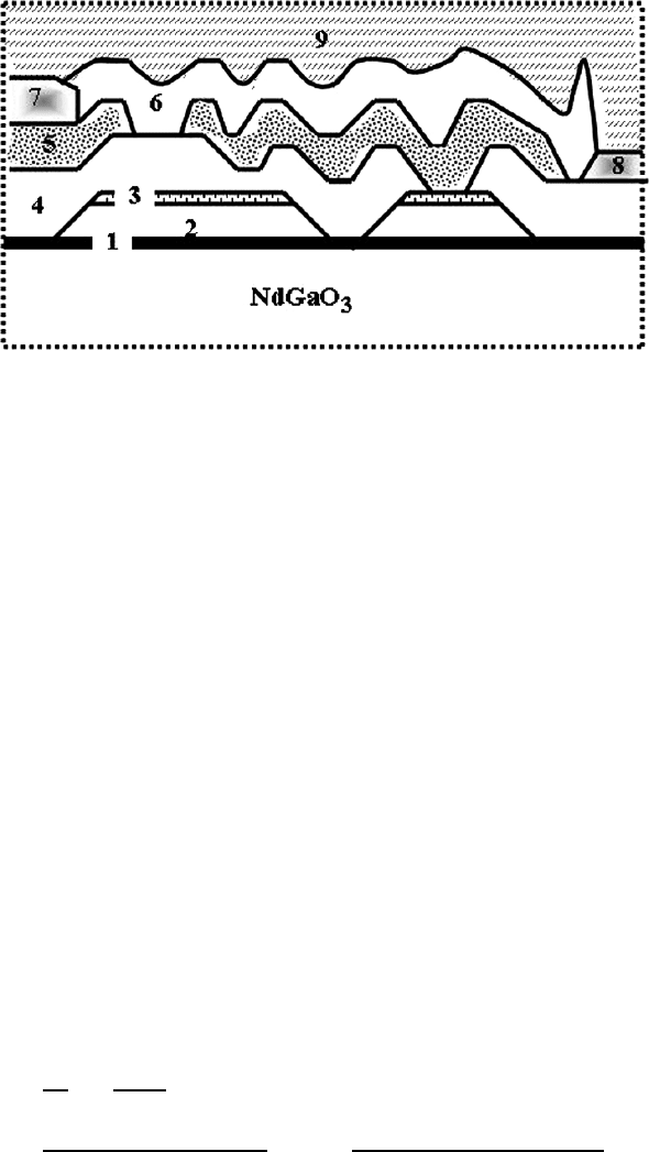
Fig. 9.1. Cross-section of HTSC JJ, consisting of nine layers, on NdGaO
3
substrate:
1 – buffer layer (30 nm), 2 – YBCO base layer (150 nm), 3 – transitional supercon-
ducting layer (150 nm), 4 – SrTiO
3
epitaxial dielectric (150 nm), 5 – YBCO top
layer (150–200 nm), 6 – non-epitaxial silicon nitride dielectric (250 nm), 7 – silver
contact layer (600 nm), 8 – molybdenum resistor (90 nm) and 9 – silver wiring layer
(600 nm) [751]
9.1 Interface Fr acture
The interface roughness in HTSC bimaterial and a crack growth near and at
the interface introduce inevitably a mixed loading mode. In this case, there
are some morphological features of fracture [263, 485, 979], shown in Fig. 9.2,
namely (i) an interface fracture; (ii) a crack growth into more brittle compo-
nent; (iii) an alternative fracture along interface or between the interface and
adjacent material; and (iv) a crack deflection from one interface to an other.
The experiments on various materials have shown that the crack path is found
by both the ratio of interface fracture energy to fracture energy of more brit-
tle component (Γ
i
/Γ
2
) and the phase angle of loading, Ψ =arctg(K
II
/K
I
),
where K
I
and K
II
is the SIF of I and II mode, respectively. On the other hand,
this angle can be coupled with the ratio of displacements – the shear to the
opening (i.e., to the ratio of ν/u) due to the insertion of Dunders parameters
(α and β) as [236]
Ψ =arctg(ν/u)−∈
0
ln r − arctg(2 ∈
0
) , (9.1)
where
∈
0
=
1
2π
ln
1 − β
1+β
; (9.2)
α =
μ
1
(1 − ν
2
) − μ
2
(1 − ν
1
)
μ
1
(1 − ν
2
)+μ
2
(1 − ν
1
)
; β =
μ
1
(1 − 2ν
2
) − μ
2
(1 − 2ν
1
)
2[μ
1
(1 − ν
2
)+μ
2
(1 − ν
1
)]
; (9.3)

9.1 Interface Fracture 409
Alumina
Alumina
YSZ
YBCO
Cracks
30 μm
Silver
Silver
Crack
BSCCO
10 μm
460 μm
Interface Crack
Au
Al
2
O
3
(a)
(b)
(c)
Al
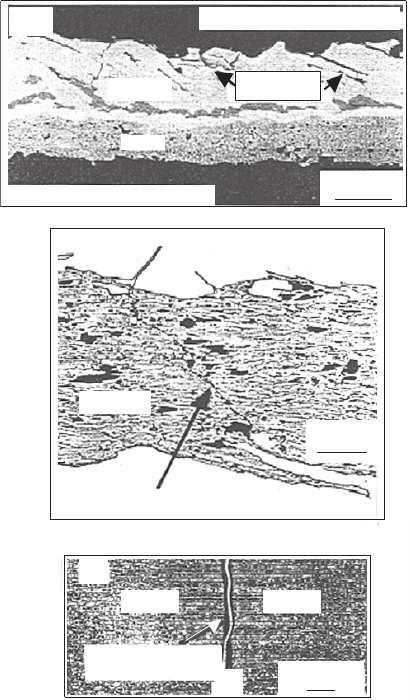
2
O
3
Fig. 9.2. Characteristic morphology of possible fractures at and near interfaces
into HTSC composite structures: (a) interface fracture and an alternative fracture
between the interface and adjacent material (SEM cross-sectional micrograph of
YBCO thick film, processed on YSZ barrier layer on alumina [979]), (b)crackgrowth
into more brittle component (Back-scattered electron image of transversal cross-
section of BSCCO/Ag tape [485]) and (c)crackinAl
2
O
3
bonded with Au, showing
a crack alternating between interfaces [263]
μ
k
and ν
k
(k =1, 2) are the shear modulus and Poisson’s ratio, respec-
tively, for k-component and r is the distance measured from the crack tip at
the interface. The parameter of α together with the dependence of Γ
i
/Γ
2
on
Ψ enables to separate the areas of the interface crack and the brittle substrate
fracture in the case of an initial crack at the interface. Then, the fracture

410 9 Mechanical Destructions of HTSC Josephson Junctions and Composites
behavior and the interface fracture energy are very sensible to a sign of the
phase angle at the great difference of the fracture energies for both components
(Γ
1
>> Γ
2
). In the case of the positive value of Ψ, there are both regimes,
namely the interface cracking and a crack deflection into more brittle com-
ponent, depending on the parameter α. The second case (when Ψ<0) is
more interesting. Therein, the greater value (i.e., Γ
1
) is compared with the
interface fracture energy Γ
i
. As the condition Γ
1
>> Γ
i
prohibits crack propa-
gation away from the interface, then there are two cases. For the low material
strength, a plastic bluntness of the crack at the interface occurs and the failure
features are caused by the toughening mechanisms, including an initiation of
voids at the interface.
1
In the contrary case, the stress state of the interface
crack interacts with microcracks and structural defects which as rule exist
in the brittle material and provoke a growth of microcracks in the direction
to the interface. This causes a saw-tooth fracture, with chips of the brittle
material attached to the interface (see Fig. 9.3).
Further more, because the complete smoothness of the interfaces is impos-
sible (e.g., see Fig. 9.4a), an estimation of the JJs fracture resistance depending
on the interface roughness is the actual problem. The crack surfaces, grow-
ing along the interface, contact each other either at the roughness or at the
facets. In this case, it is possible to obtain different values of the interface frac-
ture resistance, which grow with the phase angle of loading, Ψ. These effects
have been observed and estimated for different brittle materials [266, 482]. In
particular, a comparative analysis of microstructure properties and fracture
parameters, caused by the mixed loading mode, has been fulfilled for the fine-
grain (PbTiO
3
) and coarse-grain (BaTiO
3
) ferroelectric ceramics [816]. The
decrease of the strain energy release rate (or crack shielding) ΔG = G − G
t
(where G and G
t
are the values of the strain energy release rate connected
with applied load and at the crack tip, respectively) can be estimated using
two models: (i) the contact zone of the crack surfaces taken into account, but
without account of Coulomb’s friction [266], and (ii) the inclination angle of
the faceted interface, δ, is taken into account [482]. We have for the first model
(see Fig 9.4b) [266]:
ΔG/G =[1− λ
−2
(α)]tg
2
Ψ/(1 + tg
2
Ψ) , (9.4)
where α =(L/l
m
)/ ln[1/ sin(πD
b
/2l
m
)]. The values of the function, λ(α),
for various values of α have been tabulated in [101]. The length of the con-
tact zone, L, is found by L =(π/32)[EH/(1 − ν
2
)K
I
]
2
.Herel
m
is the
spacing between the facet centers, D
b
is the facet length and H is the
height of the interface step. The numerical approximation is obtained, tak-
ing into account the typical geometry of undulating interfaces, assuming that
1
At the same time, note that those intergranular voids formed, for example, by
thermo-mechanical treatment during a multi-stage processing of monocore Bi-
2223 tapes, may become the main cause of critical current diminution in the case
of prolonged final annealing [801]

9.1 Interface Fracture 411
Interface
1
2
K
II
K
I
Cracks
Γ
1
>>
Γ
2
Ψ
i
<
0
−
1.4
−
1.2
0.8
−
0.6
−
0.4
−
0.2
−
−π/8
0
π/8 π/4 3π/2 π/2
Interface
1
2
K
II
K
I
Ψ
i
>
0
Cracking of
Substrate
Fracture of
Interface
Phase Angle of Loading, Ψ
i
Relative Toughness, Γ
i
/ Γ
2
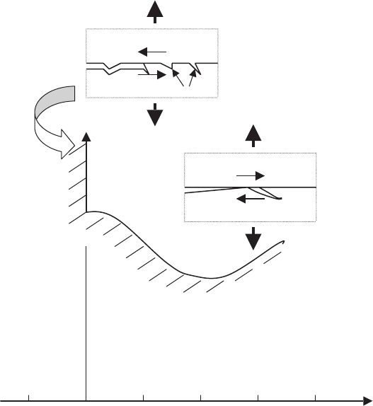
Fig. 9.3. Fracture at interface into bimaterial for Γ
1
>> Γ
2
(result in the case
of α = β = 0). When phase angle, Ψ<0, the interface fracture demonstrates
near-boundary segments of material free from cracks [263]
D
b
/l
m
∼ 1/2; H/l
m
∼ 1/2; equating K
I
to the fracture toughness, K
Ic
(which
is approximately equal to 1 MPa ·m
1/2
for a broad set of ceramics), and intro-
ducing a material parameter, χ = E
2
H/(1 −ν
2
)K
2
Ic
, which defines the length
of the contact zone, L. Note that the parameter χ in total causes a fracture
behavior in this microstructure consideration. Therefore, one should be mea-
sured with a high accuracy in order to obtain acceptable results for the HTSC
JJs. For example, the value of χ ≈ 100 has been found for the glass–polymer
interface [266].
We obtain for the second model (Fig. 9.4c) [482]:
ΔG/G =(cosδ sin Ψ − sin δ cos Ψ)
2
,Ψ>δ; H>>a, (9.5)
