Nof S.Y. Springer Handbook of Automation
Подождите немного. Документ загружается.


835
Industrial
Part F
Part F Industrial Automation
48 Machine Tool Automation
Keiichi Shirase, Kobe, Japan
Susumu Fujii, Tokyo, Japan
49 Digital Manufacturing
andRFID-BasedAutomation
Wing B. Lee, Kowloon, Hong Kong
Benny C.F. Cheung, Kowloon, Hong Kong
Siu K. Kwok, Kowloon, Hong Kong
50 Flexible and Precision Assembly
Brian Carlisle, Auburn, USA
51 Aircraft Manufacturing and Assembly
BrankoSarh,HuntingtonBeach,USA
James Buttrick, Seattle, USA
Clayton Munk, Seattle, USA
Richard Bossi, Renton, USA
52 Semiconductor Manufacturing Automation
Tae-Eog Lee, Daejeon, Korea
53 Nanomanufacturing Automation
Ning Xi, East Lansing, USA
King Wai Chiu Lai, East Lansing, USA
Heping Chen, Windsor, USA
54 Production, Supply, Logistics
and Distribution
Rodrigo J. Cruz Di Palma, San Juan, Puerto Rico
Manuel Scavarda Basaldúa, Buenos Aires,
Argentina
55 Material Handling Automation in Production
and Warehouse Systems
Jaewoo Chung, Daegu, South Korea
Jose M.A. Tanchoco, West Lafayette, USA
56 Industrial Communication Protocols
Carlos E. Pereira, Porto Alegre RS, Brazil
Peter Neumann, Magdeburg, Germany
57 Automation and Robotics in Mining
and Mineral Processing
Sirkka-Liisa Jämsä-Jounela, Espoo, Finland
Greg Baiden, Sudbury, Canada
58 Automation in the Wood and Paper Industry
Birgit Vogel-Heuser, Kassel, Germany
59 Welding Automation
Anatol Pashkevich, Nantes, France
60 Automation in Food Processing
Darwin G. Caldwell, Genova, Italy
Steve Davis, Genova, Italy
René J. Moreno Masey, Sheffield, UK
John O. Gray, Genova, Italy

836
Industrial Automation. Part F Industrial automation is well known and fascinating to all of us who were born
in the 20th century, from visits to plants and factories to watching movies highlighting the automation marvels of
industrial operations and assembly lines. This part begins with explanation of machine tool automation, includ-
ing various types of numerical control (NC), flexible, and precision machinery for production, manufacturing,
and assembly, digital and virtual industrial production, to detailed design, guidelines and application of automa-
tion in the principal industries, from aerospace and automotive to semiconductor, mining, food, paper and wood
industries. Chapters are also devoted to the design, control and operation of functions common to all industrial
automation, including materials handling, supply, logistics, warehousing, distribution, and communication pro-
tocols, and the most advanced digital manufacturing, RFID-based automation, and emerging micro-automation
and nano-manipulation. Industrial automation represents a major growth and advancement opportunity, because
as explained in this part, it can provide significant innovative solutions to the grand challenges of our generation,
including the production and distribution capacity of needed goods and equipment, as well as food, medical and
other essential sustenance supplies for the quality of life around the globe.

837
Machine Tool
48. Machine Tool Automation
Keiichi Shirase, Susumu Fujii
Numerical control (NC) is the greatest inno-
vation in the achievement of machine tool
automation in manufacturing. In this chap-
ter, first a history of the development up to
the advent of NC machine tools is briefly re-
viewed (Sect. 48.1). Then the machining centers
and the turning centers are described with
their key modules and integration into flexi-
ble manufacturing systems (FMS) and flexible
manufacturing cells (FMC)inSect.48.2. NC part
programming is described from manual pro-
gramming to the computer-aided manufacturing
(CAM) system in Sect. 48.3.InSect.48.4 and
Sect. 48.5, following the technical innova-
tions in the advanced hardware and software
systems of NC machine tools, future control
systems for intelligent CNC machine tools are
presented.
48.1 The Advent of the NC Machine Tool ........ 839
48.1.1 From Hand Tool
to Powered Machine................... 839
48.1.2 Copy Milling Machine.................. 840
48.1.3 NC Machine Tools ....................... 840
48.2 Development of Machining Center
and Turning Center............................... 841
48.2.1 Machining Center ....................... 841
48.2.2 Turning Center ........................... 843
48.2.3 Fully Automated Machining:
FMS and FMC.............................. 843
48.3 NC Part Programming............................ 844
48.3.1 Manual Part Programming........... 845
48.3.2 Computer-Assisted Part
Programming: APT and EXAPT....... 846
48.3.3 CAM-Assisted Part Programming... 846
48.4 Technical Innovation in NC Machine Tools 847
48.4.1 Functional and Structural
Innovation by Multitasking
and Multiaxis ............................ 847
48.4.2 Innovation in Control Systems
Toward Intelligent CNC Machine
Tools......................................... 848
48.4.3 Current Technologies
of Advanced CNC Machine Tools.... 849
48.4.4 Autonomous and Intelligent
Machine Tool ............................. 853
48.5 Key Technologies
for Future Intelligent Machine Tool ........ 856
48.6 Further Reading ................................... 857
References .................................................. 857
Numerical control (NC) is the greatest innovation in the
achievement of machine tool automation in manufac-
turing. Machine tools have expanded their performance
and ability since the era of the Industrial Revolution;
however all machine tools were operated manually
until the birth of the NC machine tool in 1952. Nu-
merical control enabled control of the motion and
sequence of machining operations with high accu-
racy and repeatability. In the 1960s, computers added
even greater flexibility and reliability of machining
operations. These machine tools which had computer
numerical control were called CNC machine tools.
A machining center, which is a highly automated NC
milling machine performing multiple milling opera-
tions, was developed to realize process integration as
well as machining automation in 1958. A turning cen-
ter, which is a highly automated NC lathe performing
multiple turning operations, was also developed. These
machine tools contributed to realize the flexible man-
ufacturing system (FMS), which had been proposed
during the mid-1960s. FMS aims to perform automatic
machining operations unaided by human operators to
machine various parts.
The automatically programmed tool (APT)isthe
most important computer-assisted part programming
language and was first used to generate part programs
Part F 48
838 Part F Industrial Automation
Tools
The first innovation
The first innovation
The second innovation
The second innovation
Machine tools
NC machine tools
Analog control/mechanical control
(mechanics)
The third innovation
The third innovation
Digital control with AC
(performance function/constraint conditions)
Digital control with AC
(machining strategy/decision making)
NC machine tools
with adaptive control
Intelligent
NC machine tools
Digital control
(servo, actuator, sensor)
• High speed
• High precision
• High productivity
• Motion control
• Multi tasks/multi functions
• System
• Cutting process control
• Feedback of cutting process
• Artificial intelligence
• Knowledge/knowhow
• Learning/evolution
Automatic operation
pre-instructed by NC programs
Hardware
Software
Information
Autonomous operation
instructed by in-process planning and decision
Fig. 48.1 Evolution of machine tools toward the intelligent machine for the future
in production around 1960. The extended subset of
APT (EXAPT) was developed to add functions such
as setting of cutting conditions, selection of cutting
tool, and operation planning besides the functions of
APT. Another pioneering NC programming language,
COMPACT II, was developed by Manufacturing Data
Systems Inc. (MDSI) in 1967. Technologies developed
beyond APT and EXAPT were succeeded by computer-
aided manufacturing (CAM). CAM provides interactive
part programming with a visual and graphical environ-
ment and saves significant programming time and effort
for part programming. For example, COMPACT II
has evolved into open CNC software, which enables
integration of off-the-shelf hardware and software tech-
nologies. NC languages have also been integrated with
computer-aided design (CAD) and CAM systems.
In the past five decades, NC machine tools have
become more sophisticated to achieve higher accuracy
and faster machining operation with greater flexibil-
ity. Certainly, the conventional NC control system can
perform sophisticated motion control, but not cutting
process control. This means that further intelligence
of NC control system is still required to achieve more
sophisticated process control. In the near future, all ma-
chine tools will have advanced functions for process
planning, tool-path generation, cutting process monitor-
ing, cutting process prediction, self-monitoring, failure
prediction, etc. Information technology (IT) will be
the key issue to realize these advanced functions. The
paradigm is evolving from the concept of autonomy to
yield next-generation NC machine tools for sophisti-
cated manufacturing systems.
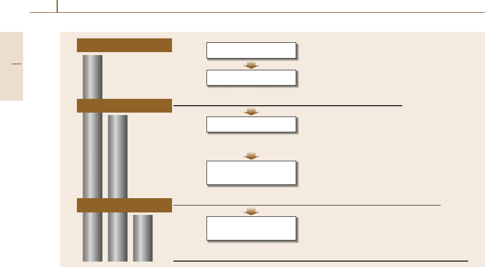
Machine tools have expanded their performance
and abilities as shown in Fig. 48.1. The first inno-
vation took place during the era of the Industrial
Revolution. Most conventional machine tools, such as
lathes and milling machines, have been developed since
the Industrial Revolution. High-speed machining, high-
precision machining, and high productivity have been
achieved by these modern machine tools to realize mass
production.
The second innovation was numerical control (NC).
A prototype machine was demonstrated at MIT in
1952. The accuracy and repeatability of NC machine
tools became far better than those of manually oper-
ated machine tools. NC is a key concept to realize
programmable automation. The principle of NC is
to control the motion and sequence of machining
operations. Computer numerical control (CNC)was
introduced, and computer technologyreplaced the hard-
ware control circuit boards on NC, greatly increasing
the reliability and functionality of NC. The most im-
portant functionality to be realized was adaptive control
(AC). In order to improve the productivity of the ma-
Part F 48
Machine Tool Automation 48.1 The Advent of the NC Machine Tool 839
chining process and the quality of machined surfaces,
several AC systems for real-time adjustment of cutting
parameters have been proposed and developed [48.1].
As mentioned above, machine tools have evolved
through advances in hardware and control technologies.
However, the machining operations are fully dominated
by the predetermined NC commands, and conventional
machine tools are not generally allowed to change the
machining sequence or the cutting conditions during
machining operations.This means that conventionalNC
machine tools are allowed to perform only automatic
machining operations that are pre-instructedby NC pro-
grams.
In order to realize an intelligent machine tool for
the future, some innovative technical breakthroughs are
required. An intelligent machine tool should be good at
learning, understanding, and thinking in a logical way
about the cutting process and machining operation, and
no NCcommands will be required to instruct machining
operations as an intelligent machine tool thinks about
machining operations, and adapts the cutting processes
itself. This means that an intelligent machine tool can
perform autonomous operations that are instructed by
in-process planning made by the tool itself. Information
technology (IT) will be the key issue to realize this third
innovation.
48.1 The Advent of the NC Machine Tool
48.1.1 From Hand Tool to Powered Machine
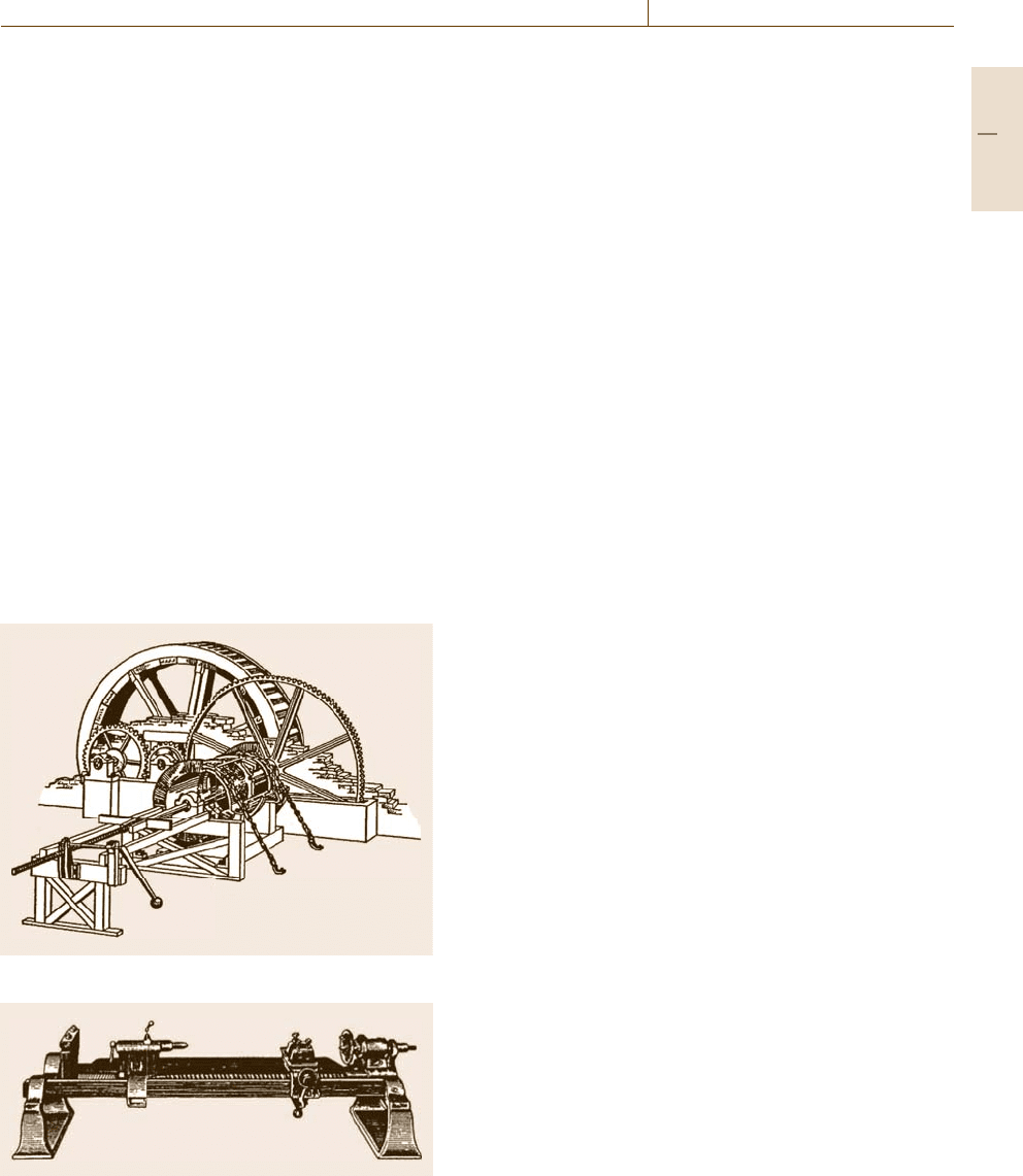
It is well known that John Wilkinson’s boring ma-
chine (Fig.48.2) was able to machine a high-accuracy
cylinder to build Watt’s steam engine. The perfor-
Fig. 48.2 Wilkinson’s boring machine (1775)
Fig. 48.3 Maudsley’s screw-cutting lathe with mecha-
nized tool carriage (1800)
mance of steam engines was improved drastically by
the high-accuracy cylinder. With the spread of steam
engines, machine toolschanged fromhand tools to pow-
ered machines, and metal cutting became widespread
to achieve modern industrialization. During the era of
the Industrial Revolution, most conventional machine
tools, such as lathes and milling machines, were devel-
oped.
Maudsley’s screw-cutting lathe with mechanized
tool carriage (Fig.48.3) was a great invention which
was able to machine high-accuracy screw threads. The
screw-cutting lathe was developed to machine screw
threads accurately; however the mechanical tool car-
riage equipped with a screw allowed precise repetition
of machined shapes. Precise repetition of machined
shape is an important requirement to produce many of
the component parts for mass production. Therefore,
Maudsley’s screw-cutting lathe became a prototype of
lathes.
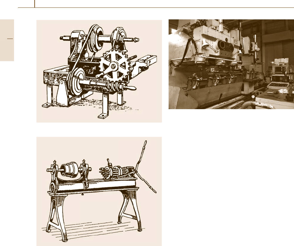
Whitney’s milling machine (Fig.48.4) is believed
to be the first successful milling machine used for
cutting plane of metal parts. However, it appears that
Whitney’s milling machine was made after Whitney’s
death. Whitney’s millingmachine wasdesigned to man-
ufacture interchangeable musket parts. Interchangeable
parts require high-precision machine tools to make ex-
act shapes.
Fitch’s turret lathe (Fig.48.5)wasthefirstauto-
matic turret lathe. Turret lathes were used to produce
complex-shaped cylindrical parts that required several
operating sequences and tools. Also, turret lathes can
perform automatic machining with a single setup and
can achieve high productivity. High productivity is an
Part F 48.1
840 Part F Industrial Automation
Fig. 48.4 Whitney’s milling machine (1818)
Fig. 48.5 Fitch’s turret lathe (1845)
important requirement to produce many of the compo-
nent parts for mass production.
As mentioned above, the most important modern
machine tools required to realize mass production were
developed during the era of the Industrial Revolution.
Also high-speed machining, high-precision machining,
and high productivity had been achieved by these mod-
ern machine tools.
48.1.2 Copy Milling Machine
A copy milling machine, also called a tracer milling
machine or a profiling milling machine, can dupli-
cate freeform geometry represented by a master model
Fig. 48.6 A copy milling machine
for making molds, dies, and other shaped cavities and
forms. A prove tracing the model contour is controlled
to follow a three-dimensional master model, and the
cutting tool follows the path taken by the tracer to ma-
chine the desired shape. Usually, a tracing prove is fed
by a human operator, and the motion of the tracer is
converted to the motion of the tool by hydraulic or elec-
tronic mechanisms. The motion in Fig.48.6 shows an
example of copy milling. In this case, three spindle
heads or three cutting tools follow the path taken by the
tracer simultaneously. In some copy milling machines
the ratio between the motionof thetracer and the cutting
tool can be changed to machine shapes that are similar
to the master model.
Copy milling machines were widely used to ma-
chine molds and dies which were difficult to generate
with simple tool paths, until CAD/CAM systems be-
came widespread to generate NC programs freely for
machining three-dimensional freeform shapes.
48.1.3 NC Machine Tools
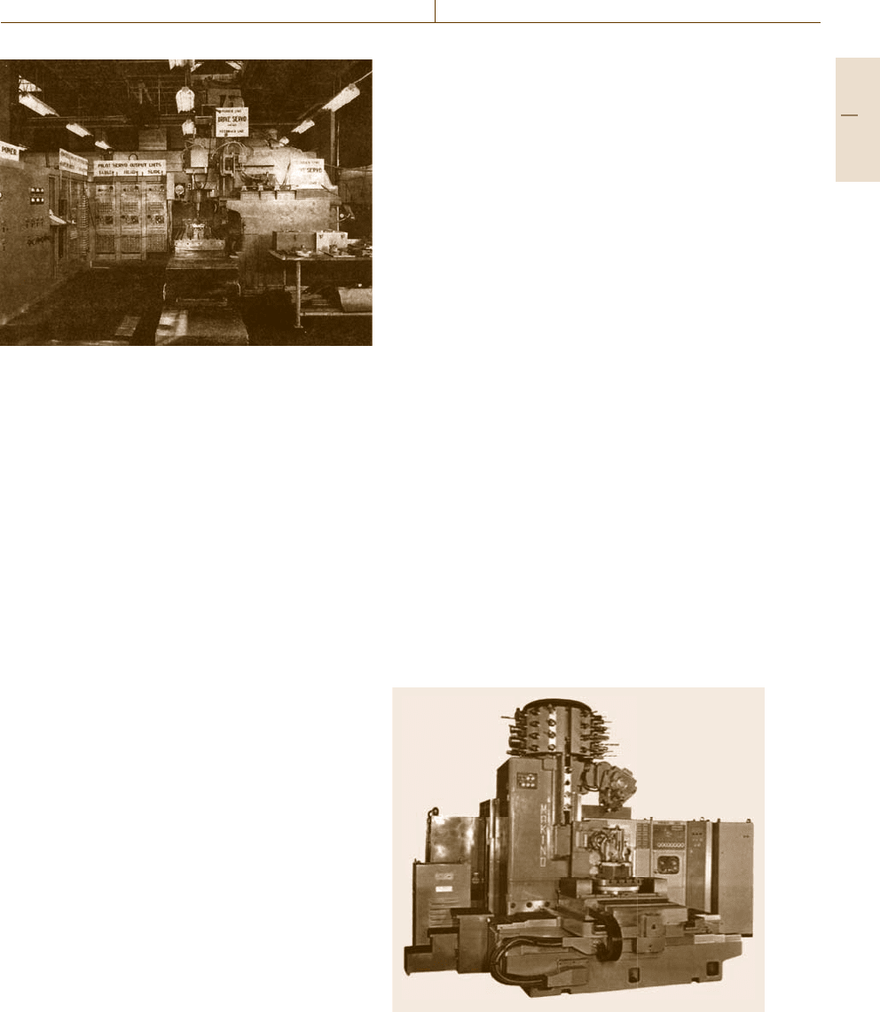
The first prototypeNC machinetool, shown inFig.48.7,
was demonstrated at the MIT in 1952. The name nu-
merical control was given to the machine tool, as it
was controlled numerically. It is well known that nu-
merical control was required to develop more efficient
manufacturing methods for modern aircraft, as aircraft
components became more complex and required more
machining. The accuracy, repeatability, and productiv-
ity of NC machine tools became far better than those of
machine tools operated manually.
The concept of numerical control is very impor-
tant and innovative for programmable automation, in
which the motions of machine tools are controlled or
Part F 48.1
Machine Tool Automation 48.2 Development of Machining Center and Turning Center 841
Fig. 48.7 The first NC machine tool, which was demon-
strated at MIT in 1952
instructed by a program containing coded alphanu-
meric data. According to the concept of numerical
control, machining operation becomes programmable
and machining shape is changeable. The concept of
the flexible manufacturing system (FMS) mentioned
later required the prior development of numerical
control.
A program to control NC machine tools is called
a part program, and the importance of a part program
was recognized from the beginning of NC machine
tools. In particular, the definition for machining shapes
of more complex parts is difficult by manual opera-
tion. Therefore, a part programming language, APT,
was developed at MIT to realize computer-assisted part
programming.
Recently, CNC has become widespread, and in most
cases the term NC is used synonymously with CNC.
Originally, CNC corresponded to an NC system oper-
ated by an internal computer, which realized storage of
part programs, editing of part programs, manual data
input (MDI), and so on. The latest CNC tools allow
generation of a part program interactively by a machine
operator, and avoid machine crash caused by a miss-
ing part program. High-speed andhigh-accuracycontrol
of machine tools to realize highly automated machin-
ing operation requires the latest central processing unit
(CPU) to perform high-speed data processing for sev-
eral functions.
48.2 Development of Machining Center and Turning Center
48.2.1 Machining Center
A machining center is a highly automated NC milling
machine that performs multiple machining operations
such as end milling, drilling, and tapping. It was devel-
oped to realize process integration as well as machining
automation, in 1958. Figure 48.8 shows an early ma-
chining center equipped with an automatic tool changer
(ATC). Most machining centers are equipped with an
ATC and an automatic pallet changer (APC)toper-
form multiple cutting operations in a single machine
setup and to reduce nonproductive time in the whole
machining cycle.
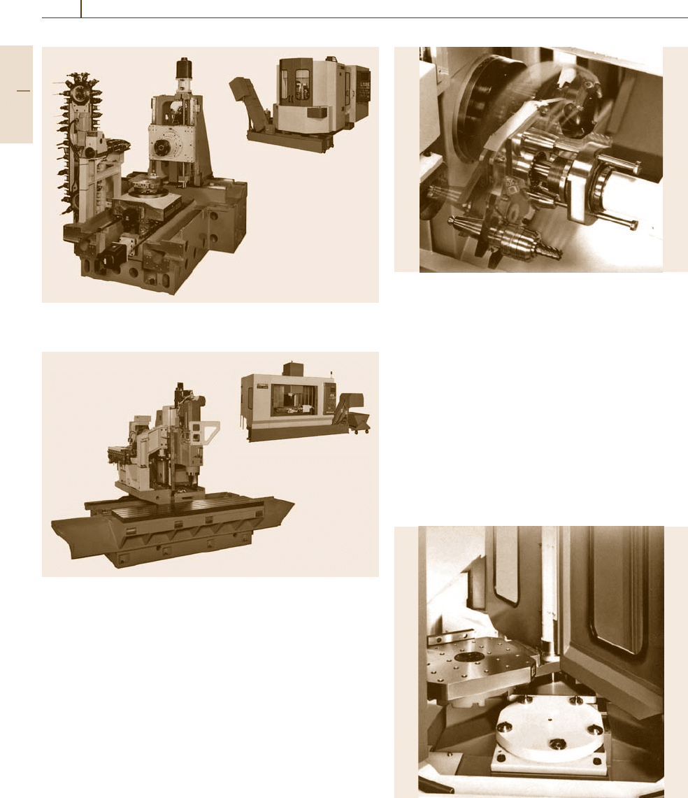
Machining centers are classified into horizontal and
vertical types according to the orientation of the spindle
axis. Figures 48.9 and 48.10 show typical horizon-
tal and vertical machining centers, respectively. Most
horizontal machining centers have a rotary table to
index the machined part at some specific angle rela-
tive to the cutting tool. A horizontal machining center
which has a rotary table can machine the four ver-
tical faces of boxed workpieces in single setup with
minimal human assistance. Therefore, a horizontal ma-
chining center is widely used in an automated shop
floor with a loading and unloading system for work-
pieces to realize machining automation. On the other
Fig. 48.8 Machining center, equipped with an ATC (cour-
tesy of Makino Milling Machine Co. Ltd.)
Part F 48.2
842 Part F Industrial Automation
Fig. 48.9 Horizontal machining center (courtesy of Yamazaki
Mazak Corp.)
Fig. 48.10 Vertical machining center (courtesy of Yamazaki Mazak
Corp.)
hand, a vertical machining center is widely used in a die
and mold machine shop. In a vertical machining cen-
ter, the cutting tool can machine only the top surface
of boxed workpieces, but it is easy for human opera-
tors to understand tool motion relative to the machined
part.
Automatic Tool Changer (ATC)
ATC stands for automatic tool changer, which permits
loading and unloading of cutting tools from one ma-
chining operation to the next. The ATC is designed to
exchange cutting tools between the spindle and a tool
magazine, which can store more than 20 tools. The
Fig. 48.11 AT C: automatic tool changer (courtesy of Ya-
mazaki Mazak Corp.)
large capacity of the tool magazine allows a variety of
workpieces to be machined. Additionally, higher tool-
change speed and reliability are required to achieve
a fast machining cycle. Figure 48.11 shows an example
of a twin-arm-type AT C driven by a cam mechanism to
ensure reliable high-speed tool change.
Automatic Pallet Changer (APC)
APC stands for automatic pallet changer, which permits
loading and unloading of workpieces for machining au-
tomation. Most horizontal machining centers have two
pallet tables to exchange the parts before and after ma-
Fig. 48.12 APC: automatic pallet changer (courtesy of Ya-
mazaki Mazak Corp.)
Part F 48.2
Machine Tool Automation 48.2 Development of Machining Center and Turning Center 843
Fig. 48.13 Turning center or CNC lathe (courtesy of Ya-
mazaki Mazak Corp.)
chining automatically. Figure 48.12 shows an example
of an APC. The operator can be unloading the finished
part and loading the next part on one pallet while the
machining center is processing the current part on an-
other pallet.
48.2.2 Turning Center
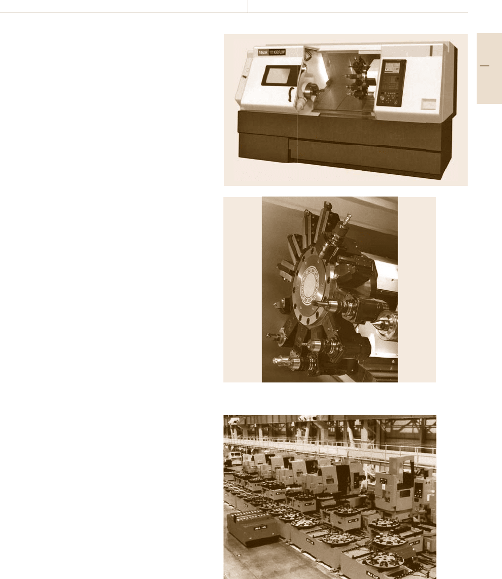
A turning center is a highly automated NC lathe to per-
form multiple turning operations. Figure 48.13 shows
a typical turning center. Changingof cutting tools is per-
formed by a turret tool changer which can hold about
ten turning and milling tools. Therefore, a turning cen-
ter enables not only turning operations but also milling
operations such as end milling, drilling, and tapping in
a single machine setup. Some turning centers have two
spindles and two or more turret tool changers to com-
plete all machining operations of cylindrical parts in
a single machine setup. In this case, the first half of the
machining operations of the workpiece are carried out
on one spindle, then the second half of the machining
operations are carried out on another spindle, without
unloading and loading of the workpiece. This reduces
production time.
Turret Tool Changer
Figure 48.14 shows a tool turret with 12 cutting tools.
A suitable cutting tool for the target machining opera-
tion is indexed automatically under numerical control
for continuous machining operations. The most sophis-
ticated turning centers have tool monitoring systems
which check tool length and diameter for automatic
tool alignment and sense tool wear for automatic tool
changing.
48.2.3 Fully Automated Machining: FMS
and FMC
Flexible Manufacturing System (FMS)
The concept of the flexible manufacturing system
(FMS) was proposed during the mid-1960s. It aims to
perform automatic machining operations unaided by
human operators to machine various parts. Machining
centers are key components of the FMS for flexible ma-
chining operations. Figure 48.15 shows a typical FMS,
which consists of five machining centers, one conveyor,
one load/unload station, and a central computer that
controls and manages the components of the FMS.
Fig. 48.14 Tool turret in turning center (courtesy of Ya-
mazaki Mazak Corp.)
Fig. 48.15 Flexible manufacturing system (courtesy of Ya-
mazaki Mazak Corp.)
Part F 48.2
844 Part F Industrial Automation
No manufacturing system can be completely flex-
ible. FMSs are typically used for mid-volume and
mid-variety production. An FMS is designed to ma-
chine parts within a range of style, sizes, and processes,
and its degree of flexibility is limited. Additionally,
the machining shape is changeable through the part
programs that control the NC machine tools, and the
part programs required for every shape to be ma-
chined have to be prepared before the machining
operation. Therefore a new shape that needs a part pro-
gram is not acceptable in conventional FMSs, which
is why a third innovation of machine tools is re-
quired to achieve autonomous machining operations
instead of automatic machining operations to achieve
true FMS.
An FMS consists of several NC machine tools such
as machining centers and turning centers, material-
handling or loading/unloading systems such as indus-
trial robots and pallets changer, conveyer systems such
as conveyors and automated guided vehicles (AGV),
and storage systems. Additionally, an FMS has a central
computer to coordinate all of the activities of the FMS,
and all hardware components of the FMS generally
have their own microcomputer for control. The central
computer downloads NC part programs, and controls
the material-handling system, conveyer system, storage
system, and management of materials and cutting tools,
etc.
Human operators play important rolesin FMSs, per-
forming the following tasks:
1. Loading/unloading parts at loading/unloading sta-
tions
2. Changing and setting of cutting tools
3. NC part programming
4. Maintenance of hardware components
5. Operation of the computer system.
These tasks are indispensable to manage the FMS suc-
cessfully.
Flexible Manufacturing Cell (FMC)
Basically, FMSs are large systems to realize manu-
facturing automation for mid-volume and mid-variety
production. In some cases, small systems are applicable
to realize manufacturing automation. The term flexible
manufacturing cell (FMC) is used to represent small
systems or compact cells of FMSs. Usually, the number
of machine tools included in a FMC is three or fewer.
One can consider that an FMS is a large manufacturing
system composed of several FMCs.
48.3 NC Part Programming
The task of programming to operate machine tools au-
tomatically is called NC part programming because the
program is prepared for a part to be machined. NC part
programming requires the programmer to be familiar
with both the cutting processes and programming pro-
cedures. The NC part program includes the detailed
commands to control the positions and motion of the
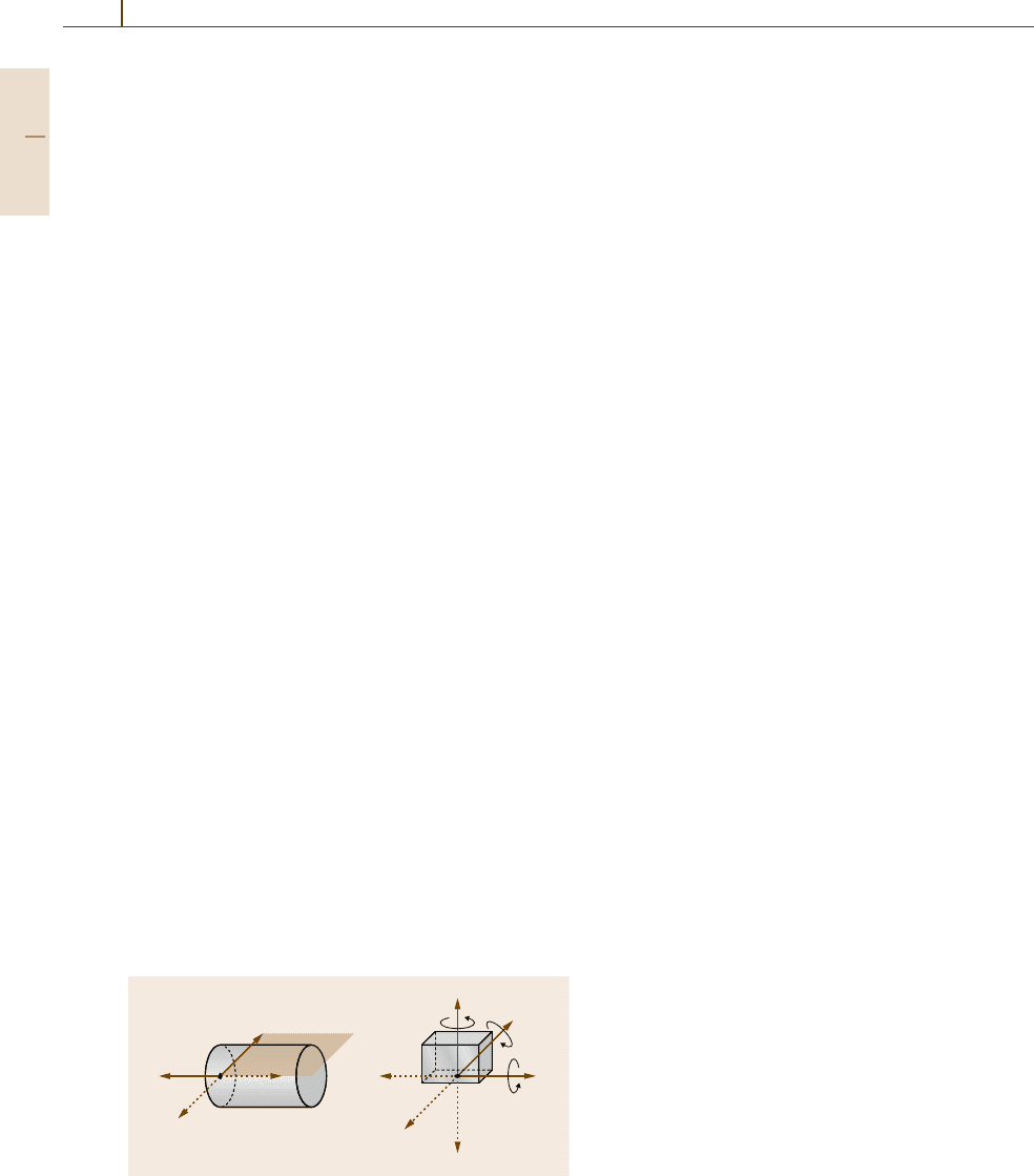
machine tool. In numerical control, the three linear axes
(x, y, z) of the Cartesian coordinate system are used
+z
a) b)
+x
–z
–x
–x
+y
+x
+z
–z
+a
+b
+c
–y
Fig. 48.16a,b Coordinate systems in numerical control.
(a) Cylindrical part for turning; (b) cuboid part for
milling
to specify cutting tool positions, and three rotational
axes (a, b, c) are used to specify the cutting tool pos-
tures. In turning operations, the position of the cutting
tool is defined in the x–z plane for cylindrical parts, as
showninFig.48.16a. In milling operations, the position
of the cutting tool is defined by the x-, y-, and z-axes for
cuboid parts, as shown in Fig.48.16b.
Numerical control realizes programmable automa-
tion of machining. The mechanical actions or motions
of the cutting tool relative to the workpiece and the con-
trol sequence of the machine tool equipments are coded
by alphanumerical data in a program. NC part program-
ming requires a programmer who is familiar with the
metal cutting process to define the points, lines, and
surfaces of the workpiece, and to generate the alphanu-
merical data. The most important NC part programming
techniques are summarized as follows:
1. Manual part programming
2. Computer-assisted part programming – APT and
EXAPT
3. CAM-assisted part programming.
Part F 48.3
