Morris & Fan. Reservoir Sedimentation Handbook
Подождите немного. Документ загружается.


SEDIMENT EXCAVATION 16.26
B
V
c
V
i
c
i
where B = bulking factor, V = volume, γ = dry unit weight, and subscripts c and i refer to
the containment area and in situ conditions, respectively.
The bulking factor for a particular sediment may be determined in two ways: (1) it
may be estimated from prior experience and the type sediment to be excavated or (2) it
may be determined by using the column settling tests described in the next section. Table
16.5 summarizes the typical range of bulking factors experienced as a function of type of
sediment. For clays, the bulking factor will depend heavily on the degree of flocculation,
and higher bulking factors also tend to be associated with clays of higher initial density
and higher plasticity. Coarse sediment (sand) has a bulking factor close to 1.0.
Sediment composition will vary from one part of a reservoir to another, and so will
the bulking factor. The bulking factor also depends on the time allowed for consolidation.
If a thin (e.g., 1 m) layer of sediment is deposited in a containment area one year, and is
allowed to dry prior to discharge of additional dredged material the following year, the
bulking factor will be lower than for continuous discharge. These effects are considered
in establishing the sizing factor, which is the ratio of total containment volume to the total
dredged volume. If there are multiple containment areas, the sizing factor may differ for
each. Dredging in the delta region of a reservoir may produce a slurry containing a high
percentage of coarse material and a low bulking factor. In contrast, material dredged
farther downstream may consist of clays which dewater very slowly and have a high
bulking factor.
16.6.2 General Containment Area Considerations
On level ground, a containment area which is approximately square will minimize the
length of the required dike construction per unit of volume. However, it will produce a
configuration with a high degree of hydraulic short-circuiting, which reduces effective
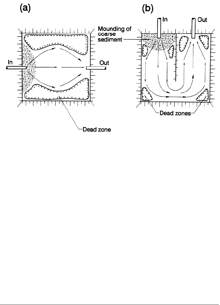
residence time and thus sedimentation efficiency. The use of one or more interior dikes
will provide the hydraulic barrier required to produce an elongated flow path which
reduces the effect of hydraulic short-circuiting (Fig. 16.14). The containment area
configuration will also be influenced by factors including local topography, operational
requirements, and long-term management objectives (e.g., future reuse).
TABLE 16.5 Bulking Factors for Various Sediments
Sedimented dry Bulking factor
Material bulk density, kg/m
3
USAE Huston Others
Clay 480-1250 1.2-3.1 1.45
Recent clay deposits 1.3
Silty clay 1.4-1.7
Sandy clay 1.25
Clayey sand 1.3
Silt 1.1-1.4 2.0 1.3
Silty fine sand 1.1
Sand 1490 1.0-1.2 1.0
USAE = U.S. Army Corps of Engineers.
Source: Adapted from Herbich (1992).
SEDIMENT EXCAVATION 16.27
FIGURE 16.14 Use of interior dikes to reduce the amount of hydraulically dead zones
within containment areas by limiting hydraulic short-circuiting. (a) High degree of short-
circuiting. (b) Use of interior dike to reduce short-circuiting
In a long-duration project dredging clays that have a high bulking factor and that
dewater and compact slowly, the tendency for the sediment to compact under self-weight
as additional material is added will be offset by the poor permeability of the fine material.
The fine sediment having a high void ratio will resist compaction, and a large percentage
of the containment area will be occupied by voids rather than sediment. If land area is
limited it can be advantageous to divide the containment area into multiple compart-
ments. The dredge may pump into different containment areas, or different cells within a
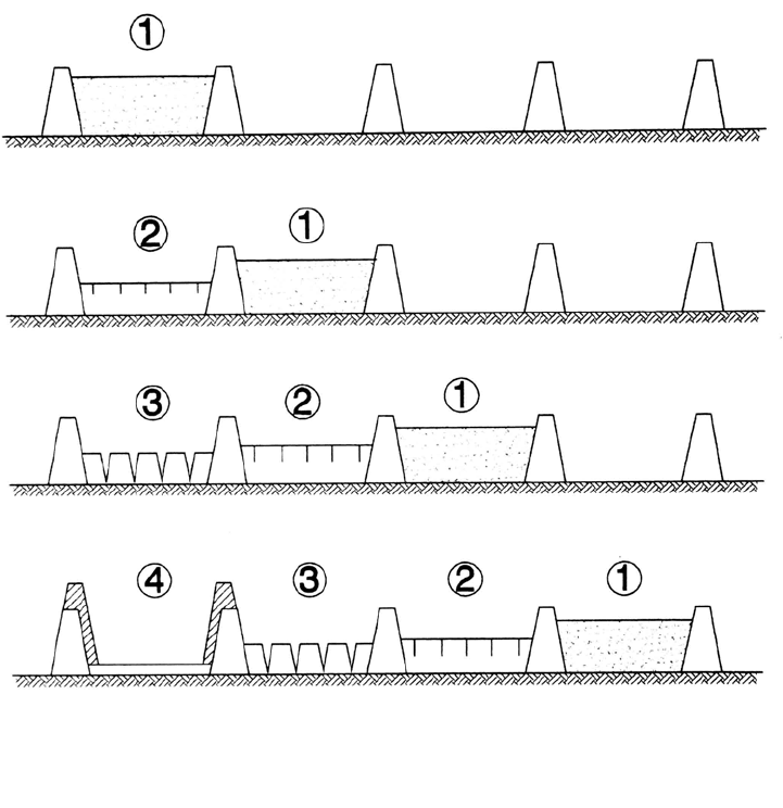
single containment area, on rotating sequence. Within any given containment area the
first lift of dredged material (perhaps 1 m thick) would be allowed to dewater and
compact for a season before a subsequent lift is added (Fig. 16.15). Vegetative growth
assists dewatering when the roots penetrate and extract water from deeper in the soil
column. For more information on dewatering strategies, see U.S. Army (1987),
Haliburton (1978), and Montgomery et al. (1978).
When sediment enters the disposal area, the coarse material will settle out near the
pipeline discharge point, and fines will settle across the remainder of the basin, as
illustrated in Fig. 16.3. Under favorable conditions this coarse material may be used to
build up the dikes.
16.7 COLUMN SETTLING TESTS
Column settling tests may be used to determine the settling and compression
characteristics of dredged sediments. Reservoir sediments often exhibit zone
or hindered
settling characteristics, meaning that a sharp interface forms between the settling
sediment and the clear supernatant, typically within 24 hours. The sediment mass is
slowly compressed as its internal flocculant structure collapses under self-weight, and
water seeps upward to the surface, often through small vertical pipes. Particles remaining
in the supernatant will settle individually.
SEDIMENT EXCAVATION 16.28
FIGURE 16.15 Containment area management to dewater sediment. (1) Fill with slurry; (2)
dewatering; (3) desiccation; (4) use dried sediment to raise dikes to repeat cycle. (Modified
from U.S.Army Corps of Engineers, 1987.)
In the hydraulic sizing of a containment area two factors are of primary importance:
the volume needed to store the dredged sediment, and the surface area needed to meet
effluent standards. Design criteria for both can be determined from a single column
settling test. These tests should be conducted with a slurry concentration equal to that
expected during dredging (usually about 150 g/L for fines).
16.7.1 Column Test Procedure
The U.S. Army (1987) describes a procedure which uses about 50 L of sediment and a
settling column approximately 2 m tall and at least 20 cm (8 in) in diameter. The Army
recommends against the use of a smaller-diameter column because of wall effects. The
Army's procedure describes zone, compression, and flocculant settling tests, the last of
which requires withdrawal ports at several levels in the column and the construction of
concentration profiles (previously described in Sec. 5.5.7). The procedure described
below is a simplification of the Army procedure in that samples for flocculant settling are
withdrawn from only one level. The procedure is as follows:
1. Construct a 20-cm-diameter Plexiglas settling column with an air supply introduced at
the bottom to mix the slurry prior to the test. To construct a sediment concentration
profile multiple ports will be required (Fig. 16.16).

SEDIMENT EXCAVATION 16.29
FIGURE 16.16 Equipment for column settling test of dredged sediments (after U.S. Army Corps o
f
E
ngineers, 1987).
2.
Collect approximately 55 L of sediment, which may be a composite taken from
several different areas. If sediment characteristics change appreciably from one area to
another in the reservoir, and this sediment will be discharged into different containment
areas, sample and test source material for each containment area separately.
3. Mix sediment with native water and allow coarse material to settle out. This
simulates conditions in the disposal area where the coarse sediment settles out near the
inlet pipe and the fines settle and compact separately.
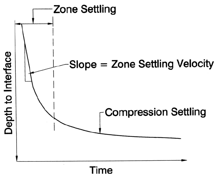
4. Conduct a pilot settling test in a 4-L graduated cylinder using a slurry concentration
of about 150 g/L. If an interface forms within several hours, the slurry mass is exhibiting
zone settling. Record the settling rate of the interface over time. The break in the settling
curve (Fig. 16.17) will define the concentration at which compression settling begins. If
SEDIMENT EXCAVATION 16.30
FIGURE 16.17 Plot of the settling of the sediment interface over time in column settling tes
t
(after U.S. Army Corps of Engineers, 1987).
no
break occurs, sedimentation began in the compression zone and the test should be
rerun using a lower-concentration slurry. If no interface is observed within the first
several hours, the slurry is experiencing flocculant settling. Use this test to define the
initial sediment concentration to be used in the 20-cm column.
5. Run the settling test in the 20-cm column with a concentration less than that
associated with compression settling in the 4-L pilot column. Fill the large column with
slurry of the appropriate dilution, air-agitate to achieve a uniform mixture. To begin the
test, stop agitation and immediately withdraw a 50-mL sample to determine the initial
solids concentration.
6. Record the height of the sediment-water interface at various points in time. Be-
cause settling rate declines over time, the following intervals may be used for sampling:
1, 2, 4, 6, 12, 24, 48, 96 hours, etc., for at least 15 days. These sampling times may be ad-
justed. If a sediment-water interface forms in less than an hour, this should be recorded.
In other cases many hours may be required for the formation of a distinct interface.
7. At each sampling time, withdraw 50-mL supernatant samples from 0.3 m below
the surface (representative of discharge over the weir) and analyzed for suspended solids.
From these data three types of design determinations can be made.
16.7.2 Zone Settling Test
When zone settling occurs, the zone settling test defines the minimum surface area
required for effective settling and retention of the sediment. The supernatant above the
interface may continue to have sediment concentrations of several grams per liter, and a

SEDIMENT EXCAVATION 16.31
surface area much greater than that determined by zone settling may be required to attain
the required effluent water quality standards.
Plot the depth to the sediment interface over time, and compute the zone settling
velocity as the slope of the initial straight part of the curve in Fig. 16.17. For zone
settling, the minimum ponded area required for separation of solids from the clear
supernatant liquid is given by:
A
Q
i
V
s
C
h
(16.1)
where A = area required for setting, m
2
; = inflow rate, m
3
/h; V
S
= zone settling velocity
from the settling test, m/h; and C
h
= correction factor for hydraulic efficiency, discussed
below (U.S. Army, 1987).
The zone settling velocity is equivalent to the surface loading rate, defined as the
discharge divided by surface area. This is demonstrated by rearranging Eq. (16.1) in the
following form:
V
s
Q
i
A
(16.2)
Whereas the hydraulic retention time will vary as a function of water depth, the surface
loading rate is constant for a given basin geometry and is a better indicator of the
sedimentation efficiency of a shallow basin than retention time.
16.7.3 Compression Settling Test
The compression settling test is used to estimate the volume required for initial storage of
dredged material, prior to dewatering. This uses the same graph as the zone settling test,
but extended for 16 days to determine the compression settling rate (Fig. 16.17).
The volume that will be occupied by the dredged sediment can be determined from
the average suspended solids concentration in the settled sediment. The mean sediment
concentration below the sediment-water interface can be computed from the interface
height at any time by:
C
t
C
i
H
i
H
t
(16.3)
where C = slurry concentration, g/L; H
= height of interface from bottom of column, m;
and subscripts i and t represent initial and subsequent points in time. The computed
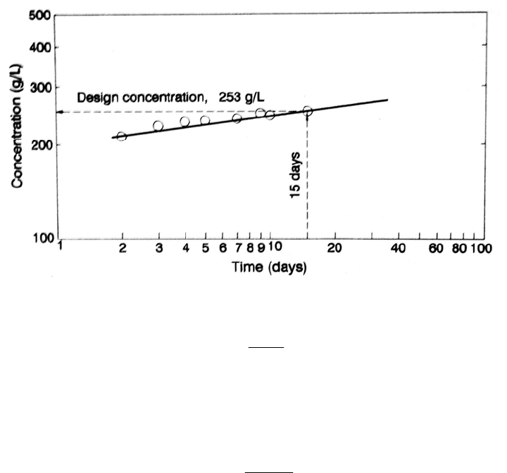
concentration values at each point in time are then plotted as a function of time on a log-
log scale (Fig. 16.18), and this plot can then be used to determine the average sediment
concentration in the settled sediment. Solids in the supernatant above the interface are
neglected.
Once the rate of consolidation has been determined, the bulking factor is determined
from the void ratio. For sizing a containment area, the bulking factor should be based on
a time period equal to half the dredging time; half the sediment will be stored for a longer
time and half for a shorter time. The dredging time is determined by dividing dredge
production rate into the volume of sediment to be dredged.
Use the log-log graph of concentration versus time (Fig. 16.18) to determine the mass
concentration of sediment C in the disposal area at time equal to one-half the dredging
time. This, the design concentration, is then used to compute the average void ratio of
fine-grained sediment in the containment area at the completion of dredging by:
SEDIMENT EXCAVATION 16.32
FIGURE 16.18 Timewise increase in fine sediment concentration within a containment area
U.S. Army Corps of Engineers, 1987). (after
1
C
G
e
s
(16.4)
where e = void ratio; G
s
= specific gravity of sediment (usually 2.65); ρ = density of
water, g/L; and C = mass sediment concentration, g/L. Compute the volume occupied by
fine sediment in the containment area at the end of dredging, V
0
, in m
3
by:
1
1
r
ro
ro
e
ee
VV
(16.5)
where e
r
= average in situ void ratio of sediment in the reservoir prior to dredging based
on data from cores; e
o
= void ratio computed for containment area; and V
r
= in situ vol-
ume of sediment to be dredged from the reservoir, m
3
. To compute the total volume
required for sediment storage in the containment area, add the volume occupied by coarse
sediment using the assumption that no bulking of coarse sediment will occur (U.S. Army,
1987).
16.7.4 Achievement of Strict Effluent Standards
Regulatory agencies may require that suspended solids levels of 50 mg/L or lower be
achieved in the effluent from the disposal area. The individual suspended particles in the
supernatant above the sediment interface within the water column will exhibit flocculant
settling, and the surface loading rate required to achieve a low level of suspended solids
in the effluent can be much lower than that required for zone settling. Under favorable
conditions these levels may be attained in disposal area effluent by plain sedimentation,
given adequate sedimentation time. In Lake Springfield, for example, an effluent quality
standard of 15 mg/L was regularly achieved.
A high-quality effluent can usually be achieved by a combination of: (1) adequate
detention time, or low surface loading rate, without hydraulic short-circuiting; (2) low
SEDIMENT EXCAVATION 16.33
weir overflow rates; and (3) water level manipulation. The following design procedure
for achieving high effluent standards by plain sedimentation within the containment area
is based on design experience at reservoir dredging projects in the midwestern United
States (Berrini, 1996).
1. Conduct the column settling test as described above, withdrawing suspended samples
at a constant depth of about 0.15 m below the water surface. This represents,
approximately, the average quality of the water that will be discharged over the weir
with a minimum 0.6 m ponding depth.
2. From the samples, determine the detention time t required to achieve the required
effluent standard.
3. Compute the required surface area of the basin, A, based on hydraulic detention time,
t, and a 0.6-m minimum ponding depth, D, using A = Qt/D. Alternatively, compute
the surface loading rate by V = D/t, and from this compute the required surface area
by A = Q/V, where Q = pumping rate. Both methods produce the same surface area.
4. Design an adjustable effluent weir with stop logs to permit water level management.
As a rule of thumb, limit the depth of overflow across the weir to 0.15 m, which is
equivalent to a weir overflow rate of about 0.09 m
3
/s per meter of weir length (1 ft
3
/s
per foot or 7.5 gal/min per foot).
Sediment and water chemistry conditions in some areas can produce clay suspensions
that resist settling, and in windy areas wave action can continually resuspend shallow
sediment. There are three basic alternatives. The first alternative is to pass the effluent
through a shallow vegetated polishing pond, which will have better settling
characteristics than an open water body. The second alternative is to increase ponding
depth. The third alternative is to use a chemical flocculant. When a flocculant is used, the
containment area would be constructed with a final basin, and the flow would enter this
final basin through a static mixing device where the flocculating polymer is added. The
flocculated sediment will settle into this last compartment and clarified water discharged
over a weir. The injection of polymer at the exit of the dredge discharge line is not
recommended.
16.7.5 Hydraulic Efficiency
The nominal residence time in a containment area may be computed as the water volume
divided by discharge rate. However, hydraulic short-circuiting can reduce the true
hydraulic detention time or surface loading rate to a value significantly less than the
nominal value determined be geometric computations. In a perfect plug flow reactor, the
detention time of all inflowing water will equal the nominal detention time. However,
because of hydraulic short-circuiting, the detention period will vary and some of the
water and its suspended sediment will pass rapidly to the outlet, while other parts of the
basin act as dead zones (Fig. 16.14). This section outlines a procedure for estimating the
deviation from theoretical conditions (U.S. Army Corps of Engineers, 1987).
The correction factor for hydraulic efficiency of a basin, C
h
, is the ratio of the
nominal
.
residence time T to the field residence time T
f
:
C
h
T
/
T
f
(16.6)
In an existing basin a tracer test may be used to determine the field residence time in the
basin and, from this, C
h
. Tracer test procedures are outlined by the U.S. Army Corps of
Engineers (1987). For new containment areas the following equation can be used:

SEDIMENT EXCAVATION 16.34
1
C
h
T
f
T
0.9(1 e
0.3(L /W )
)
(16.7)
where L/W is the length:width ratio of the proposed basin. Configurations which produce
a more elongated flow path, or the use of several compartments in series, will reduce the
effect of short-circuiting compared to a square basin. The effective L/W ratio can be
increased by using internal dikes.
16.7.6 Weir Length
In practice the overflow weir will not merely skim off the surface layer of water, but it
will also draw water up from deeper depths. The greater the discharge rate per linear
meter of weir, the greater will be this aspiration effect and the deeper the depth of
upwelling in front of the weir. The required weir length will depend on the settling
characteristics of the sediment and the effluent quality standards.
The U.S. Army Corps of Engineers (1987) developed a nomograph for the
relationship between the maximum weir overflow rate and ponding depth, presented
below as equations in both the International System of Units (SI) and U.S. Customary
Units:
For zone settling:
SI: D = 0.06 + 6.56 Q
w
(16.8)
U.S. Customary: D = 0.2 + 2 Q
w
(16.9)
For flocculant settling:
SI: D = 0.34 + 6.56 Q
w
(16.10)
U.S. Customary: D = 1.1 + 2 Q
w
(16.11)
In these equations D
= ponding depth at the weir (m, ft) and Q
w
= discharge per unit
length of weir (m
3
/s per linear meter, ft
3
/s per linear foot). These equations may be used
for weir loading rates not exceeding 0.14 m
3
/s per linear meter (1.5 ft
3
/s per linear foot),
which corresponds to a maximum water depth over the weir of about 0.2 m.
Because the sediment surface will tend to slope from the inlet zone to the outlet weir,
the ponding depth at the weir can be expected to be deeper than the average ponding
depth. The ponding depth at the weir can be estimated by:
D
w
= D
ave
+ 0.0005 L (16.12)
where D
w
= ponding depth at the weir, D
ave
= average ponding depth for the entire
detention area, and L = length of ponded surface between inflow and weir.
The "effective" weir length will depend on weir geometry, with the idea being to
minimize the approach velocity. The effective length of a horizontal or a rectangular weir
extending from the dike into the containment area is equal to the total weir length. Use of
a labyrinth weir in this application will not reduce the approach velocity. For a shaft-type
weir, the weir should be located far enough away from dikes to allow flow to enter
unobstructed from all sides. This criterion is met when the distance from the nearest dike
or other flow obstruction is 1.5 times the required weir length determined by using the
nomograph [Eqs. (16.8) through (16.11)].

SEDIMENT EXCAVATION 16.35
16.7.7 Retention Time for Flocculent Settling in Supernatant Water
When zone settling occurs, flocculant settling of the individual particles in the
supernatant above the solids interface will determine the solids concentration in the
effluent, and will control detention area design to meet effluent water quality
requirements. The normal test procedures for flocculant settling are performed, except
only the portion of the water column above the sediment interface is used. Computations
are as before, producing a family of curves of mean retention time versus percentage
solids removal, one curve for each depth (each sample port).
16.8 FLOW CONDITIONS IN SLURRY PIPELINES
16.8.1 Flow Regimes
The hydraulics of sediment-water mixtures or slurries flowing in pipelines have been
previously summarized by Graf (1971) and Herbich (1992). The flow of sediment-water
mixtures in pipelines may be divided into three regimes based on the composition of the
mixture and pipe diameter.
1. Pseudo-homogeneous regime occurs when all particles are in suspension and there
is little variation in the concentration from the top to the bottom of the pipe. This
condition generally requires that flow velocity within the pipe be at least two orders of
magnitude greater than the particle sedimentation rate. Mixtures consisting of sediments
having particle diameters smaller than about 0.03 mm may be considered to be
nonsettling and will characteristically exhibit pseudo-homogeneous flow characteristics.
2. Heterogeneous regime occurs when all particles are in motion but the vertical
sediment distribution is not uniform. At higher velocities within the heterogeneous flow
regime, all the particles travel in suspension at essentially the same speed as the fluid. At
lower velocities within this regime, the larger grains form a bed of saltating particles
which move at a slower velocity than the remainder of the flow, but which do not form a
stationary deposit within the pipeline.
3. Stationary bed regime occurs when the coarse fraction of the sediment load forms
a stationary bed with bed load transport along the surface of the deposit. Bed forms such
as ripples and dunes can form on the stationary bed.
Each of these conditions is schematically illustrated in Fig. 16.19, along with the
equation defining the approximate transition point between each regime. The boundaries
between these regimes are not distinct and the transition from one to another is gradual.
Furthermore, conditions can change from one regime to another as the dredge excavates
through sediment layers having different grain size characteristics. Therefore, in dredging
of coarse material it is not generally possible to continuously operate at an optimal zone
with respect to pipeline hydraulics.
The general shape of the curve of head loss as a function of discharge for different
sediment concentrations is illustrated in Fig. 16.20. The point of minimum head loss at a
given concentration, and therefore the most economical operating point for a slurry
pipeline, will correspond to the lowest velocity at which all the sediment remains in
motion, i.e., the lowest velocity in the heterogeneous flow regime. At lower velocities,
sediment settles to create a stationary bed, reducing the pipeline cross-sectional area and
increasing head loss. Graf (1971) has pointed out that a slurry pipeline should normally
be operated at a higher velocity to prevent deposition of bed and the potential for
blockage.