Morris & Fan. Reservoir Sedimentation Handbook
Подождите немного. Документ загружается.


FLUSHING 15.24
to redistribute sediment within the reservoir by removing it from the upper pool and
redepositing it closer to the dam (Lara, 1973)
15.7.3 Flushing Efficiency with Emptying
The flushing efficiency achieved at several sites under conditions of reservoir emptying is
summarized in Table 15.4. These are mean values for the entire event, including the
period of extremely high sediment removal at the beginning of the event as well as the
subsequent period of lower-concentration discharge and low flushing efficiency.
Reported values for flushing efficiency vary widely and are heavily influenced by flush-
ing duration, and will also be heavily influenced by the amount of sediment inflow during
the preceding impounding period. For example, flushing efficiency during 36 events at
Zemo-Afchar varied from 0.006 to 0.12 (computed with data from Gvelessiani and
Shimaltsel, 1968). In laboratory tests of reservoir flushing by Lai and Shen (1996), about
half the total volume of sediment removed was eroded during the first third of the
flushing period, producing a pattern of flushing efficiency which was initially high (about
0.10) when retrogressive erosion was initiated, and declined asymptotically to a lower
level (about 0.025).
A high flushing efficiency is not necessarily synonymous with desirable or effective
sediment management. For example, the flushing efficiency for the removal of coarse
material will necessarily be lower than for fines, and if a site is operated to maximize
flushing efficiency it may continuously accumulate coarse sediment. High flushing effi-
ciency may also generate sediment concentrations downstream which are excessive from
the standpoint of other users or the environment.
TABLE 15.4 Flushing Efficiency for Reservoir Emptying
Reservoir
Years of
Operation
Discharge,
m
3
/s
Duration of
Flashing
Flushing
efficiency
Water:sediment
ratio
Gebidem,
Switzerland
1969-1994 35 35 h/yr 0.048-
0.060
21-17
Barenburg,
Switzerland
1985 90 20 h 0.06 17
Ferrera,
Switzerland
1985
0.026 38
Gen-shan-pei,
China
1958-1983
53 days/yr 0.0897 11
Santo
Domingo,
Venezuela
1978 8-10
0.09-0.13 11-8
Donfanghong,
China
1984 51
0.056-
0.083
18-12
Sefid-Rud,
Iran
1980-1987
61-157
days
0.022-
0.067
45-15
Zemo-Afchar,
U.S.S.R
1939-1966 72-688 13-76 h 0.015-
0.096
67-10
Chirurt,
U.S.S.R.
1968 400-500 5 days 0.04 25
FLUSHING 15.25
15.8 AUXILIARY FLUSHING METHODS
Natural processes that erode floodplain deposits include tributary stream channels that
enter the reservoir and direct rainfall impact on deposits exposed during flushing. Neither
causes significant erosion of deposits, and, when floodplain sediments are exposed to air
during flushing events, their surface layers can become hardened thereby increasing their
resistance to erosion. The only effective hydraulic means to remove floodplain deposits is
by erosion using auxiliary flushing channels arranged either laterally or longitudinally
across the sediment deposits. Auxiliary channels can scour sediment from a larger portion
of the reservoir than the single main channel. Sediment removal can also be assisted by
mechanical methods.
15.8.1 Lateral Erosion
The use of auxiliary flushing channels which drain laterally across floodplain deposits,
from the sides of the reservoir into the main flushing channel, is termed lateral erosion.
This technique was first implemented and described by Xia (1989) at Heisonglin
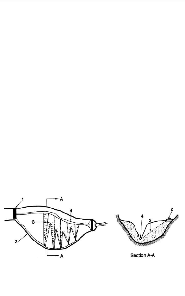
Reservoir in China (sec. 25.8). Figure 15.14 illustrates the principal components of the
system including the upstream diversion dam, supply channel, and lateral channels for
scouring sediment.
Lateral erosion is undertaken by diverting river flow into a supply channel following
the margin of a reservoir, releasing this flow at various points, and allowing it to flow
across floodplain deposits toward the main channel. Lateral erosion can only be per-
formed after a flushing channel has been established. The desired scour pattern may be
laid out beforehand by digging a series of shallow pilot trenches extending across the
sediments from the supply channel to the main flushing channel. These may be excavated
while the reservoir is empty or during impounding periods using a dredge. Sediment
excavated from the pilot channels may be placed on the adjacent channel banks, since
they will collapse and the sediment will be carried away as the lateral channel is
deepened and widened.
Lateral erosion has the advantage of using relatively short channels with high slopes
between the supply channel turnout and the main channel invert. Sediment removal can
FIGURE 15.4 Conceptual layout of auxiliary channels for lateral erosion. (1) Diversion
dam. (2) Diversion channel. (3) Thalweg of lateral channel. (4) Main flushing channel.
Based on layout at Heisonglin Reservoir, China.

FLUSHING 15.26
be achieved with relatively low discharges, especially in silty deposits. However, because
erosion rate is greatly accelerated and a wider channel can be created by using higher
flow rates, the supply channel and turnouts should be designed to use the highest flow
rate possible. The Sefid-Rud case study (sec. 23.5) describes the use of piping to establish
lateral erosion channels in areas of cohesive sediment overlying permeable sands.
Data on lateral erosion at several sites in China are summarized in Table 15.5. The
3.5-Mm
3
Hongqi Reservoir in Shaanxi Province, China, lost 36 percent of its storage
capacity within 5 years, and a variety of methods for removing the silt deposits were
tested and compared, as summarized in Table 15.6. The high efficiency of lateral erosion,
as reflected in the high discharge concentration, was attributed to the high lateral slopes
that could be developed between the supply channel and the flushing channel invert.
Lateral slopes were 4 to 15 times greater than the longitudinal slope at this site (Zhang et
al., 1992).
15.8.2 Longitudinal Erosion
The concept of longitudinal erosion by a diversion channel is similar to that of lateral
erosion, but uses a different geometry. One or more longitudinal pilot channels excavated
parallel to the main channel are eroded by using water from a tributary or by diversion of
the main river. Flow along the pilot diversion channel erodes sediment as in the original
formation of the main flushing channel. This method was field-tested using a single large
channel at the Sefid-Rud Reservoir and is described in Sec. 23.6.
TABLE 15.5 Lateral Erosion at Selected Chinese Reservoirs
Reservoir
Sediment
inflow,
m
3
/yr
Reporting
period,
years
Total
erosion
duration,
months
Mean
erosion
discharge,
m
3
/s
Mean
sediment
removal,
m
3
/day
Total
sediment
removed,
m
3
Heisonglin 530,000 1980-85 6.8 0.2 4000 816,000
Guanshan 120,000 1984-88 3.9 0.29 2900 344,000
Shiaodaokuo 415,000 1982 2 0.15 1400 80,000
Hongqi 148,000 1988-90 2.8 0.1-0.3 2100 175,000
Source: Fan (1995).
TABLE 15.6 Comparison of Silt Removal Methods Used at Honggi Reservoir, China
Method
Range of flow,
m
3
/s
Average discharge
concentration, g/L
Cost,
yuan/m
3
Lateral erosion 0.14-0.23 219-271 0.037
Emptying and flushing 0.12 34-57
Hand labor and flushing* 0.12-0.24 116-232 0.02-0.10
Siphon dredge 0.3-0.82 61-250 0.16
New reservoir 1.00
*Hand labor used to direct flow and facilitate bank collapse
Source: Zhang et al. (1992).
FLUSHING 15.27
Because sediment deposits slope laterally, pilot excavation is required to define the
desired course of a longitudinal channel and to maintain the required horizontal distance
between channels. Diverted flow enlarges the pilot channel until the entire flushing flow
passes through the auxiliary channel at the highest flow rate possible, thereby maxi-
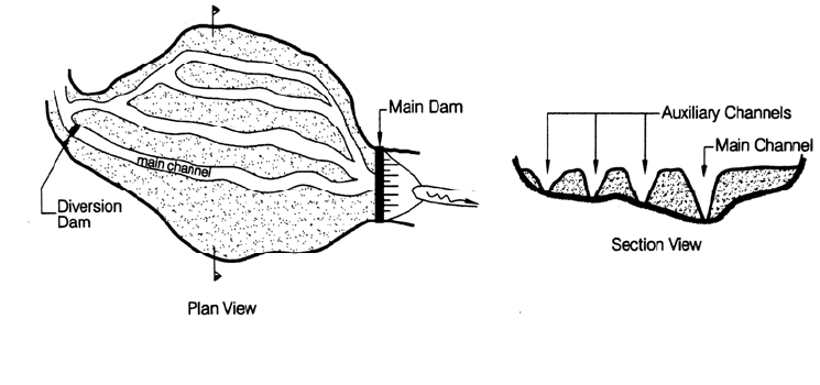
mizing channel width. A fully developed system would consist of a series of longitudinal
channels, submerged during impounding and exposed during flushing. Once the channels
have been scoured, they would be maintained by rotating the diversion flow through each
channel at regular intervals, possibly on the order of once every several years. The use of
multiple parallel longitudinal diversion channels, conceptually illustrated in Fig. 15.15,
has not yet been reported.
In narrow reservoirs with steep banks, it may be possible to construct a longitudinal
channel along one side of the deposits. Over time, the channel may move laterally (down
the reservoir sideslope) as it erodes, thereby increasing the amount of sediment removed.
Use of this technique was observed by the first author in deposits of fine sediment in the
small (2 Mm
3
) Prieto Reservoir in Puerto Rico.
Longitudinal erosion has the advantage of being able to erode large volumes of mate-
rial with a single channel. However, it must be carefully planned and implemented to
ensure that the channels remain parallel and do not intersect as a result of bank failure,
channel migration, and overflow of pilot channels. The presence of poorly consolidated
sediments can make it virtually impossible to create multiple parallel longitudinal chan-
nels, and once the floodplain has been divided up into a series of channels, access with
equipment to repair any breaches becomes difficult. Significant spacing will be required
between the diversion channels to prevent them from merging by channel migration. Any
spillage will flow laterally to an adjacent channel or to the main channel, scouring a
lateral channel that cuts off the downstream end of the planned longitudinal channel. This
problem is either minimal or absent from lateral erosion since the auxiliary channels are
oriented downgradient across sediment beds.
15.8.3 Flow Diversion
Both lateral and longitudinal erosion use flushing flows diverted from the main channel.
The construction and use of an ungated earthen diversion dam is described in the Sefid-
Rud case study (Chap. 23). In that case, the diversion dam was designed to pass the entire
river discharge and to be submerged by the reservoir pool before the onset of large floods
to prevent failure by overtopping. The upstream limit of the diversion channel feeding
FIGURE 15.15 Conceptual layout of diversion channels for longitudinal erosion.
FLUSHING 15.28
either lateral or longitudinal channels must be located at the diversion dam, which itself
must be constructed in an area far enough upstream to have sediment deposits of
adequate strength yet beyond the area of delta deposition which could bury the diversion
structure. It may also be feasible to construct the diversion system above the normal pool
elevation. Construction of a diversion dam can interfere with the passage of turbid
density currents along the main channel. Since sediment focusing into flushing channels
is an important aspect of sediment control by flushing, the diversion system should
facilitate the continued passage of turbidity currents during impounding to minimize
deposition on floodplain areas.
15.8.4 Mechanically Assisted Flushing
Mechanical equipment such as bulldozers has been used to push sediment deposits into
the flushing channel, thereby removing sediment faster than would occur by erosion
alone and also removing sediment from an area wider than the flushing channel itself. In
1992 Los Angeles County used flushing to sluice 1.7 Mm
3
of sediment from the San
Gabriel debris basin over a 5-month period, using bulldozers to push the sediment into
the flushing channel. The cost of this operation was about $0.93/m
3
, mostly bulldozer
costs. A similar but smaller-scale pilot sluicing operation at Morris Dam cost $1.42/m
3
.
This sediment sluicing method has since been discontinued because of downstream
environmental concerns related to sediment discharge (Kumar, 1995). If banks of a
flushing channel are high, their collapse can be accelerated by excavation at the base of
deposits by pressurized water or explosives. Although the use of explosives was con-
sidered at Sefid-Rud, as described in the case study (sec. 23.3.3), there is no record to
date of its successful utilization to assist flushing in any reservoir.
15.9 STORAGE HISTORY CURVES
The long-term variation in reservoir storage when flushing is used to combat sedimen-
tation depends on: (1) the rate of sediment accumulation on floodplain deposits, (2) the
storage volume in main and auxiliary flushing channels, and (3) the accumulation of
coarse material that is not removed by flushing. Assuming a reservoir is operated in con-
ventional impounding mode for a number of years, and that flushing is initiated when
half the storage capacity has been lost, the timewise variation in storage may follow the
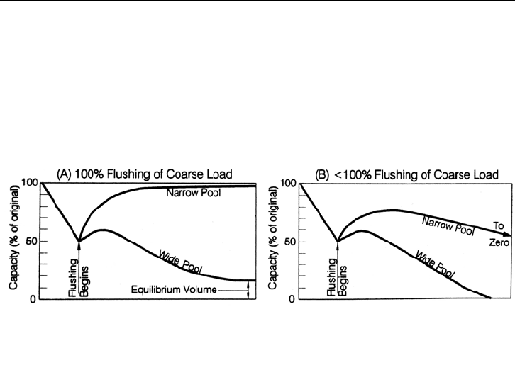
generalized storage history curves shown in Fig. 15.16. The curves in Fig. 15.16a illus-
trate the condition in a reservoir where there is no net accumulation of coarse material;
FIGURE 15.16 Long-term variation in reservoir storage with flushing, as a function of reservoi
r
geometry, for two bed load conditions: (a) all inflowing bed load is released by flushing and (b)
coarse load continuously accumulates.

FLUSHING 15.29
that is, the entire inflowing load is removed by flushing. There is an immediate increase
in capacity associated with flushing channel formation. In a narrow reservoir where the
flushing channel occupies virtually the entire pool width, it is possible to restore and
maintain most of the original storage volume. In a wide reservoir, a single flushing
channel will produce only a temporary increase in capacity, and continued sediment
deposition on submerged floodplains will cause the reservoir to decline to some stable
volume, equal to the volume within the main flushing channel. The rate of storage loss
declines as soon as flushing is initiated because sediment deposition is focused in the
flushing channel. This reduces the rate of sediment deposition on floodplains as com-
pared to continuous impounding. The rate of deposition on the floodplain will decline
over time, as will the rate of rise in floodplain height. Sediment inputs become more
focused within the channel as bank height increases and water depth over the floodplain
decreases (Fig. 15.2). The use of auxiliary flushing channels has the effect of producing a
curve intermediate between that for a wide and a narrow reservoir.
The curves in Fig. 15.16b show the same wide and narrow reservoirs as before, but
with the accumulation of coarse material that is not removed by flushing because the
flushing discharge is too small or of insufficient duration. Although bed material is typ-
ically a small fraction (e.g., 10 percent) of total sediment inflow, its volume may be large
compared to the flushing channel volume. To the extent that coarse bed material
deposition becomes focused in or along the flushing channel, its overall impact on sed-
iment accumulation can be much larger than suggested by simply comparing the volume
of bed material to the total reservoir volume. If the coarse fraction of the inflowing load
is not removed by flushing, the capacity of both the narrow and the wide reservoir will
eventually decline to zero, although at a slower rate than without flushing. The deposition
of coarse material may be countered, but not necessarily eliminated, by increasing the
discharge and duration of flushing flows. Flushing discharge may be limited by factors
such as the natural inflows during the flushing season, outlet capacity, or downstream
channel capacity.
15.10 SCOUR CONE GEOMETRY
When sediment accumulates in the area of outlets which are maintained in service by
continued withdrawals, a scour cone will develop through the sediment deposits. As a
first approximation, the bottom of this cone may be estimated to be approximately as
large as the outlet cross section and located at the outlet invert elevation. Actually, some
scour does occur immediately in front of the outlet, influenced by factors including sub-
merged angle of repose of the sediment, inflow and outflow of water and sediment, outlet
geometry, and local obstructions or other conditions that obstruct the flow field. Scour
cone geometry is not fixed, but is influenced by changing discharge conditions (Jin,
1992). Both Jin (1992) and Fang and Cao (1996) reported that the angle of repose in
reservoir scour cones is smaller in the direction extending upstream from the dam along
the longitudinal axis (a axis), compared to the transverse sediment slopes perpendicular
to the outlet axis, the b axis as illustrated in Fig. 15.17. Fang and Cao reported that
laboratory studies show the side slopes for scour cones to be approximately equal to the
submerged angle of repose of the sediment. However, field data for scour cone slope
angles in silty sediments at several Chinese reservoirs subject to drawdown (Table 15.7)
are considerably smaller than the slope angles determined from laboratory hydraulic
models. The scour cone angle in these reservoirs was influenced by drawdown. In
reservoirs not subject to drawdown the scour cone may be estimated by the submerged
angle of repose for granular sediment (Fig. 5.9). The angle of repose for continuously

FLUSHING 15.30
FIGURE 15.17 Sketch of scour cone upstream of a submerged outlet.
TABLE 15.7
Field Data on Scour Cone Slope Angles for Chinese Reservoirs
Scour cone angle, degrees
Reservoir
Annual
sediment
load, 10
6
m
3
Initial storage
volume, 10
6
m
3
a axis b axis
Kongazhue 33.7 357 6 —
Bikou 18.9 512 3.4-5.4 8-17
Qington Gorge 139 606 4-7 9-4
Fen He 17.8 702 9.5-11 13-17
Yan Gou Gorge 58.5 216 7-9 11-15
Source: Fang and Cao (1996)
submerged cohesive sediment may be significantly steeper than for noncohesive
sediment, as observed from unpublished reservoir measurements in Switzerland
(DeCesare, 1995). If the bottom outlet is not operated during periods of significant inflow
the scour cone can become filled with sediment, burying the outlet. If the reservoir is
emptied and flushed with free flow through the bottom outlet, there will be a channel
extending upstream from the outlet rather than a localized cone.
15.11 COMPARTMENTED AND MULTIPLE RESERVOIRS
A reservoir in which the total storage volume is divided into two independently operating
storage units is termed a compartmented reservoir. The compartments may be con-
tiguous, may consist of a smaller compartment inside a larger one, or may consist of two
separate storage areas operated as a single system. Storage compartmentation allows the
two portions of the total storage pool to be operated separately to enhance overall sedi-
ment management.

FLUSHING 15.31
15.11.1 Parallel Storage Compartments
If a storage reservoir is divided into two sides, one side may be operated for storage while
the other side is emptied for flushing. The Dalingkou Reservoir in Hebi Province of
China took advantage of local topography by building two parallel reservoirs connected
by a water supply tunnel. The reservoir in the smaller watershed with better vegetation
was mainly used as clear-water storage for water supply while the other was used for
flood retention. This layout permitted continuous storage for water supply in one
reservoir while sediment flushing was conducted at the other (Xia, 1983).
15.11.2 Reserve Storage Compartment
Some reservoirs may have multiple uses with large differences in water demand, such as
a reservoir making seasonally large irrigation deliveries and smaller but continuous
deliveries to a potable water system. Reservoir compartmentation may be required to
enable the main storage pool to be seasonally emptied or flushed, while continuing to
supply water from a small storage compartment created by damming a tributary branch
receiving low sediment loading.
15.11.3 Reservoirs in Series
When several reservoirs are located in series along a stream, sediment released during
flushing at an upstream site will simply accumulate in the downstream site unless both
are managed conjunctively. An example of sediment management at three reservoirs in
series is provided by the flushing experience at the Rioni hydropower reservoirs in the
Republic of Georgia. Best results were obtained when flushing was initiated at the down-
stream reservoir, scouring out a main channel to transport through the impoundment the
sediments subsequently released by flushing the upstream sites. If the upstream reservoir
is flushed first and a channel has not been scoured through the bed of the downstream
reservoir, the sediments released from the upstream site will spread out and settle on the
floodplain deposits in the downstream reservoir (Kereselidze et al., 1985).
At Jiaojiazhuang in the Hebi Province of China, two reservoirs were constructed in
series, 2.5 km apart. The initial stage of the flood containing high sediment concentra-
tions is allowed to pass through the upper reservoir and the gates are closed to retain the
clearer water in the falling limb of the hydrograph. The muddy flow passing through the
upstream reservoir is captured at the downstream site. After the water in the downstream
reservoir has been diverted to beneficial use, the clear water from the upstream reservoir
is released to scour the deposited sediment from the downstream site (Zhang et al., 1976).
15.12 PLANNING AND IMPLEMENTATION
Before undertaking flushing, it would normally be desired to answer questions such as:
what volume of storage can be recovered, how much water will be released, what will be
the downstream sediment concentration, how large should bottom outlets be, and what is
the recommended flushing schedule? These questions can be addressed only
approximately, and field conditions can depart significantly from predictions and mod-
eling results.
FLUSHING 15.32
15.12.1 Downstream Impacts
A critical issue to be addressed in any reservoir emptying or flushing operation is that of
downstream impacts. Sediment released by flushing will be redeposited somewhere
downstream: in the stream channel, a downstream reservoir, water intakes and delivery
systems, the sea, etc. Flushing is not feasible at many sites because of downstream water
quality impacts. Furthermore, the discharge required to prevent excessive localized
accumulation downstream of the dam may be more critical in determining the hydraulic
requirements for flushing than the discharge needed to erode sediment from the reservoir
itself. Problems associated with downstream redeposition are described in both the
Sanmenxia and Gebidem case studies (Chaps. 24 and 21). Potential impacts to down-
stream infrastructure and the environment due to flushing are reviewed in Chap. 18.
15.12.2 Scheduling of Flushing
The optimal flushing schedule from the standpoint of sediment removal may create sig-
nificant operational conflicts, and selection of a workable flushing schedule will normally
be reached through a process of compromise. The flushing schedule and procedures
should be modified according to monitoring data to minimize adverse impacts while
achieving sediment management objectives. Monitoring data should include downstream
impacts as well as sedimentation processes in the reservoir.
At many reservoirs in China, flushing occurs during the first part of the flood season
when large flushing discharges are available and downstream irrigation requirements can
be supplied from run-of-river diversions. The large sediment inflows during this period
can also be routed through the empty impoundment. The use of high-velocity irrigation
canals can minimize the problem of sediment deposition despite high sediment
concentrations in the flushing flow.
At reservoirs with regular seasonal variations in water level, emptying for flushing
will logically be scheduled during the period of low pool level. The flushing period at
Sefid-Rud was selected to coincide with the period of low reservoir level and to avoid
delivery of sediment-laden water to the seasonally operated irrigation intakes down-
stream, which were not designed to handle high sediment concentrations. At Cachí
Reservoir, the 3-day flushing period is set months in advance to coincide with wet season
flows to allow rapid refilling and to also coincide with a long holiday weekend when
electrical demand is low. At the Dashidaira Dam in Japan, winter was selected for flush-
ing to minimize turbidity impacts on fishing, irrigation, and tourism (Wada, 1995).
Flushing may also be initiated when specific hydrologic conditions occur, such as
adequate dilution volume in a downstream river as described in the Gebidem case study
(Chap. 21). It may also be desirable to schedule flushing to provide a clear-water dis-
charge following flushing to help wash the released sediment through the downstream
fluvial system, as performed at some sites in France.
Flushing may not be undertaken every year. The Hengshan Reservoir (Fig. 15.4) is a
13.3-Mm
3
gorge-type impoundment with a 69-m-high dam used for flood control and
irrigation. Because this reservoir is in an arid zone and water supplies are scarce, emp-
tying and flushing is delayed until the main channel has been filled by density current
siltation, an interval of every 3 or 4 years. Following the first 8 years of impounding,
from 1966 to 1973, 3.19 Mm
3
of sediment had accumulated and deposits at the dam were
27 m thick. The reservoir was emptied for 37 days in 1974 and a storage capacity of
800,000 m
3
was recovered. In 1979, the reservoir was emptied a second time and 1.03
FLUSHING 15.33
Mm
3
of capacity was recovered. The third and fourth emptying and flushing operations
were undertaken in 1982 and 1986. During the initial period of free flow, the outflow
concentration usually reaches 1000 g/L, regardless of the discharge, and in 1974 the out-
flow concentration exceeded 1000 g/L for over 16 hours. The fines removed at this site
consist of silts (Guo and Li, 1984).
15.12.3 Sizing and Location of Bottom Outlets
In general, flushing sluices should be located as deep as possible and should be as wide
as possible. Two side-by-side sluices are preferred to two sluices at different levels, since
the former arrangement will produce lower backwater at a given discharge. To maximize
effectiveness, flushing should also be performed with the largest discharge possible (Paul
and Dillon, 1988). Sluices should be designed to produce full drawdown and free flow
conditions through the dam. Because flushing dates are often determined by operational
constraints, the outlet capacity would normally be sized to minimize backwater during
the highest flows anticipated during the period selected for flushing. Selection of the
design capacity of outlets and backwater during the design flow should be determined by
modeling.
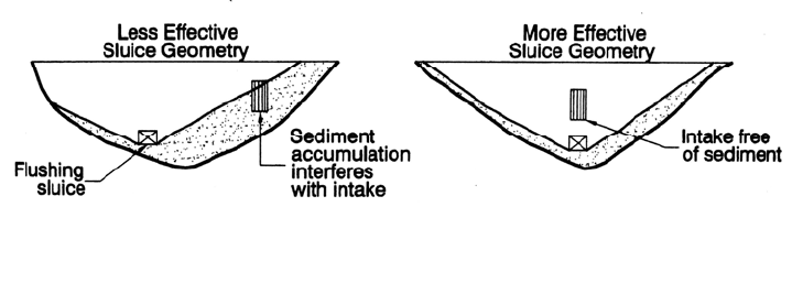
The placement of both sluices and service intakes should be planned so that the
service intakes will be maintained free of sediment by sluice operation, as conceptually
illustrated in Fig. 15.18. If intake structures are located outside the area to be maintained
sediment-free by flushing from the main channel or a lateral channel, mechanical
removal will eventually be required. When geologic or other conditions make it impos-
sible to place the flushing outlet below the service intakes, it may be feasible to divert the
flushing flow into the vicinity of the service intakes by constructing a low dike partway
across the channel upstream of the dam, thereby directing the flushing channel along the
desired alignment (Fig. 15.19). A physical model test to determine the flushing channel
alignment in the vicinity of the dam is described in Chap. 11.
15.12.4 Sediment Release and Concentration
The amount of sediment released during flushing, and the maximum sediment concen-
tration during a flushing event, is highly variable. At present there is no generally
applicable method to accurately predict the rate of sediment release, channel formation,
or peak sediment concentrations during flushing. Empirical relationships have been
developed to estimate sediment release in some reservoirs. For example, Fan and Jiang
(1980) developed the following equation from field data for the discharge of fine sand
(d50 = 0.06 to 0.09 mm) from Sanmenxia Reservoir during erosion in 1963 and 1964:
Q
S
= 3.5 × 10
-3
Q
1.2
(S ×10
4
)
1.8
(15.2)
FIGURE 15.18 Placement of sediment sluice below intake to avoid sediment buildup that
interferes with water deliveries.